 By the mid 30-ies of the aircraft type “flying wing” was quite true to their name — they were flying. In our country, in Germany, England, Switzerland, designers and innovators to pilots and enthusiasts, have managed to raise these strange machines in the air and make them confident flights. However, while none of them fly better than the plane normal scheme. Therefore they were treated as experimental and put up with some handling shortcomings.
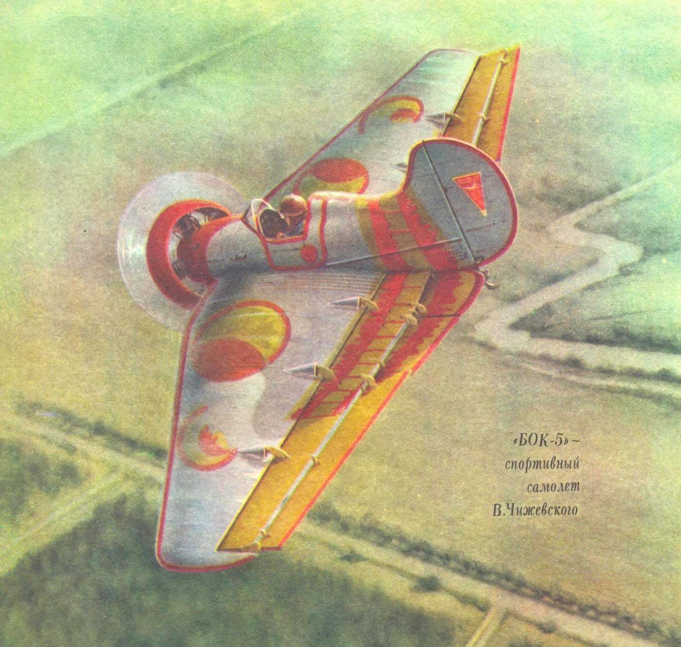
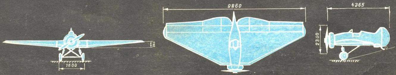
But in 1936 in our country, there were courageous aircraft designer V. Chizhevsky, who decided to build a single sport “plane-wing” for aerobatics. Single machine with motor 100 HP, according to his theory, were to become also a prototype fighter maneuvering. The plane, named “SIDE-5” (“Bureau of experimental designs”, the fifth sample), had a radial air cooled motor “M-11” power 100 HP Chassis and pull the propeller was used on U-2 (Po-2).
The fuselage was short. In the middle was the cockpit. 5 wing-shaped profile (TSAGI-890) had the narrow Central part of constant width, and the largest in scale of the console was swept shape with a straight trailing edge. Directly beneath it along the entire span wing hung (center) rudder flaps (elevators) and at the ends of the ailerons. And those and others were outside the contour of the main airfoil and had Krylova profile, but only inverted back down.
The tail flaps were rejected by the usual control stick moved by the pilot from himself (thus the back edge of the Elevator drops) and myself (the trailing edge of the Elevator rises). The ailerons are deflected when movement of the control handle, as usual, left and right. In its neutral position as the ailerons and elevators were located under a small negative angle — 4°.
“SIDE-5” – sport aircraft V. Chizhevsky
To adjust the aircraft in flight in the longitudinal with respect to the whole tail section of the wing was made movable and could deviate between +3 to -5° relative to its chord. This happened when turning the special knob, located on the left side of the cockpit. This adjustment system is well proven in flight. It is interesting to note that ten years later, in 1946, a British Builder regardless of the work of Soviet designers used the “plane-wing” company “Armstrong Whitworth” “AW-52” same adjustment system as “SIDE-5”. Directional stability “SIDE-5” was provided with a keel; it is hung the rudder by deflecting the pilot who ran the course. For this, he pressed his foot on the pedal.
The design of the “SIDE-5” mostly dural. Wing tight fitting cloth, the Central part near the fuselage were trimmed with corrugated sheet duralumin, and the frame of the rotating part is smooth aluminum. The middle part of the wing was connected tightly with the fuselage had an oval cross-section. The wing spars passed through the fuselage.
The fuselage skin sheet aluminum. In the middle section housed the cockpit, there was a cutout with a drop side. Behind the cockpit the fuselage immediately went to Kiel, ending the spar, it was to hang the rudder, and the bottom is attached to a driven crutch with rubber shock absorber. On the “Shoe” of the crutch was a ridge that helped to control the aircraft movement on the ground.
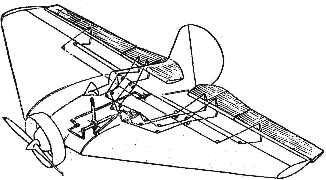
Fig. 1. Wiring of Elevator control and ailerons of the aircraft, “SIDE-5”
“SIDE-5” had experienced pilots Nogtikom M. and P. Stefanovsky. They performed on this plane complex shapes aerial acrobatics. Here’s what he wrote in his memoirs, A. Stefanovsky: “…I Sincerely admire the plane. Just can’t recommend it enough… follow me Flying the testers also praised the pilot, “SIDE-5”.
Thus was created the great aerobatic aircraft type “flying wing”. However, aviators at that time was a lot of trouble at the improvement of conventional aircraft circuit different purposes, and experts are not enough opportunities to engage more and Refine experimental car, though and a good flight attitude. Work on the further development of the “SIDE-5” stopped…
In 1933 U.S. engineers city of Sautant — aerodynamicist R. Hoffman and designer, Schneider is also aimed to create an aircraft, surpassing its flight data machines, done in the usual way. They built a light single-seat aircraft, “WESP” engine of 40 HP, a rotating pulling screw. A characteristic feature of “Arupa” there was a small lengthening of a wing — 1,4 to 6, with the usual pattern. The choice of lengthening four times less common was unexpected. Amazing seemed and wing shape in plan; a front flange extends in a straight line, and the back is almost round. Experiments in wind tunnels showed that at low elongation due to spatial flow air flow separation from the upper surface of the wing occurred at significantly high angles of attack than conventional elongation. So, for example, round wing with elongation of 1.26 stall is delayed up to 45 to 50°, the wing with aspect ratio of 5-6, the flow of air breaks down with a sock at angles of attack from 14 to 18°. This, of course, round the wing continues to increase lift by increasing angle of attack, and it turns out to be significantly larger maximum value compared to a conventional wing aspect ratio.
American designers, by choosing the elongation of the wing of 1.4, set a goal to create an aircraft with an extremely wide speed range, that is, with the greatest respect to the maximum speed to the landing. This relation is the main characteristic of the flight performance of any aircraft. In the early 30-ies in most airplanes the usual scheme it has been about 2 and sometimes reached to 2.5. Hoffman and Schneider decided to reach by plane “WESP” range of speeds of around 4. These data were expected mainly due to the decrease of the landing speed.
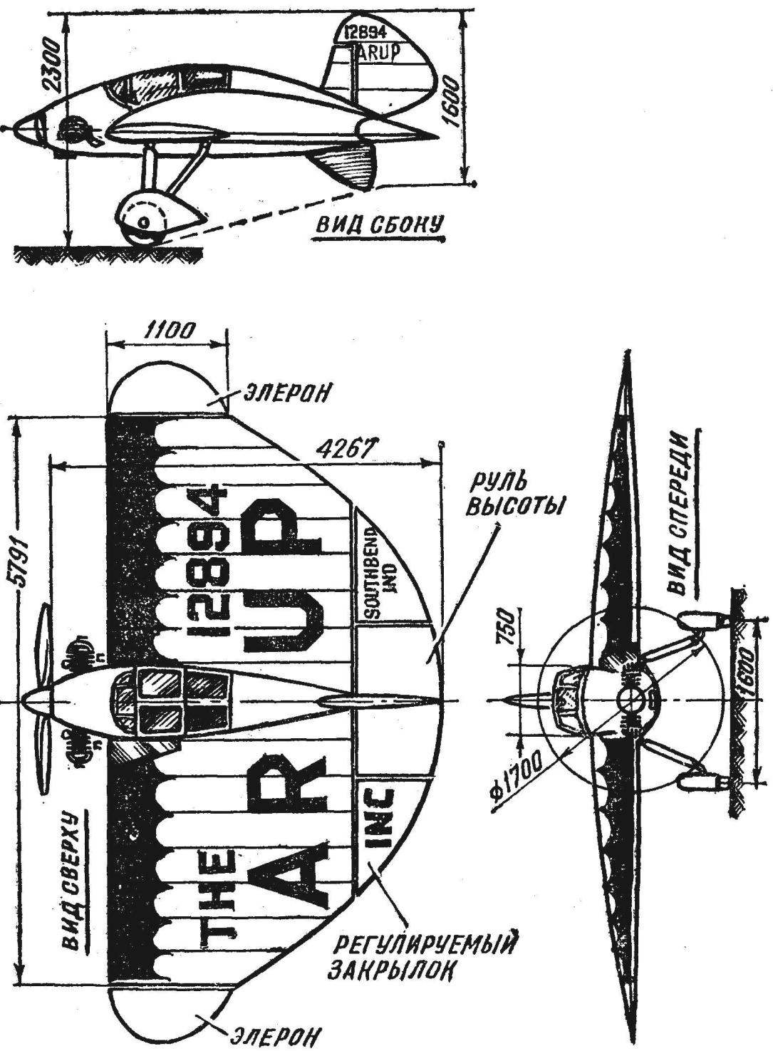
Fig. 2. The Plane “WESP”.
The wing of the plane was 5-profile of “M-6” with a relative thickness of 10%. The rear edge of the three moving parts in the center of the steering flaps operated as elevators, flanked at both sides of the flaps, deflected by a special lever to change the longitudinal balance in flight. The wing skin fabric. Ailerons — end, rotating. The vertical tail was located in the center of the wing on its upper surface; it consisted of a fin and conventional rudder. Aileron and vertical tail as the wing had fabric covering. The chassis of a conventional circuit — a two-wheeled, with the long a-pillars and damped tail crutch. The wheels are covered with fairings. Engine, two-cylinder, air-cooled, rotates a two-blade wooden propeller.
“WESP” excellent flying, it made a large number of demonstration flights that attracted a lot of spectators. Stability and control it was quite satisfactory. Extensive flight testing demonstrated that the aircraft has a high speed range equal to 4.5: at maximum flight speed—156 km/h, the smallest amounted to 35,4 km/h. At that time such a range of speeds were not available even a record aircraft with a powerful engine 400 HP
Good flight data of the aircraft allowed its creators to found a company for the construction of the apparatus of this scheme. In 1934-1935 they produced two more, already the twin plane. However, financial difficulties were not allowed to modify these cars. So sad over the development of a very original scheme “plane-wing”, which showed good stability and controllability in flight.
KOSTENKO, candidate of technical Sciences
Recommend to read
 NOW DON’T SLIP OFF
Not only plastic, but also wood rulers, especially the long, at carrying out with their help lines are often displaced under the pressure of the pencil or ruling pen. This does not... FROM A PAINT ROLLER
Film sticky tape — very convenient packaging and sealing joints material. And if operations on the gluing has to do a lot — there is a need for them to "mechanize". In this case,...
