Numerous gatherings of amateur aircraft designers brought together hundreds of small aviation enthusiasts, and this clearly showed that interest in designing amateur aircraft is enormous.
However, in many cases, an insoluble problem for ultralight aircraft enthusiasts is the engine problem — powerful, light, compact, and economical. I believe that if industry produced such engines, small aviation in Russia would develop at much higher rates. Well, for now, the only solution for homebuilders remains making such a motor with their own hands.
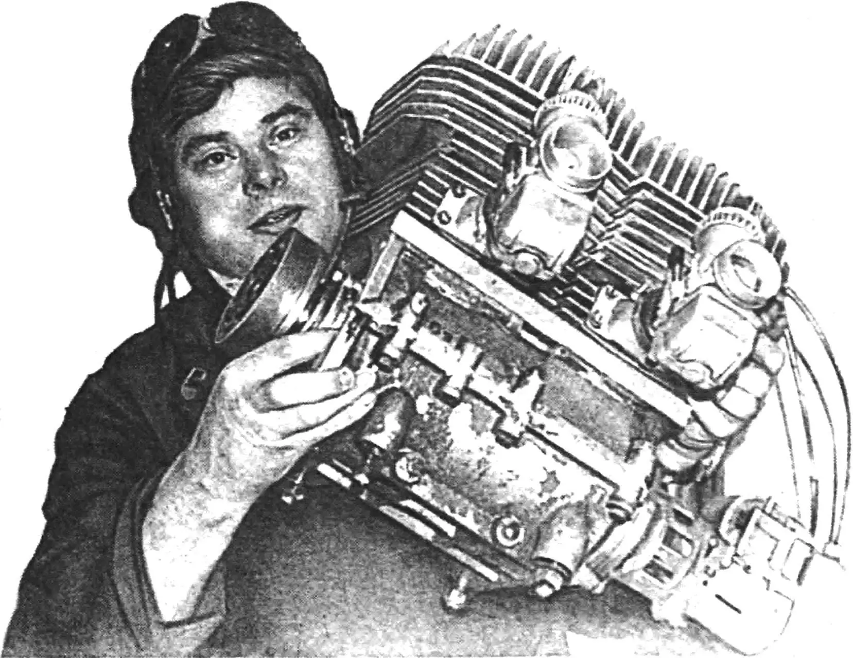
I offer amateur aviators the experience of manufacturing this type of engine, which concentrates both the joys of success and the bitterness of disappointments, and also quite a lot of time and material resources.
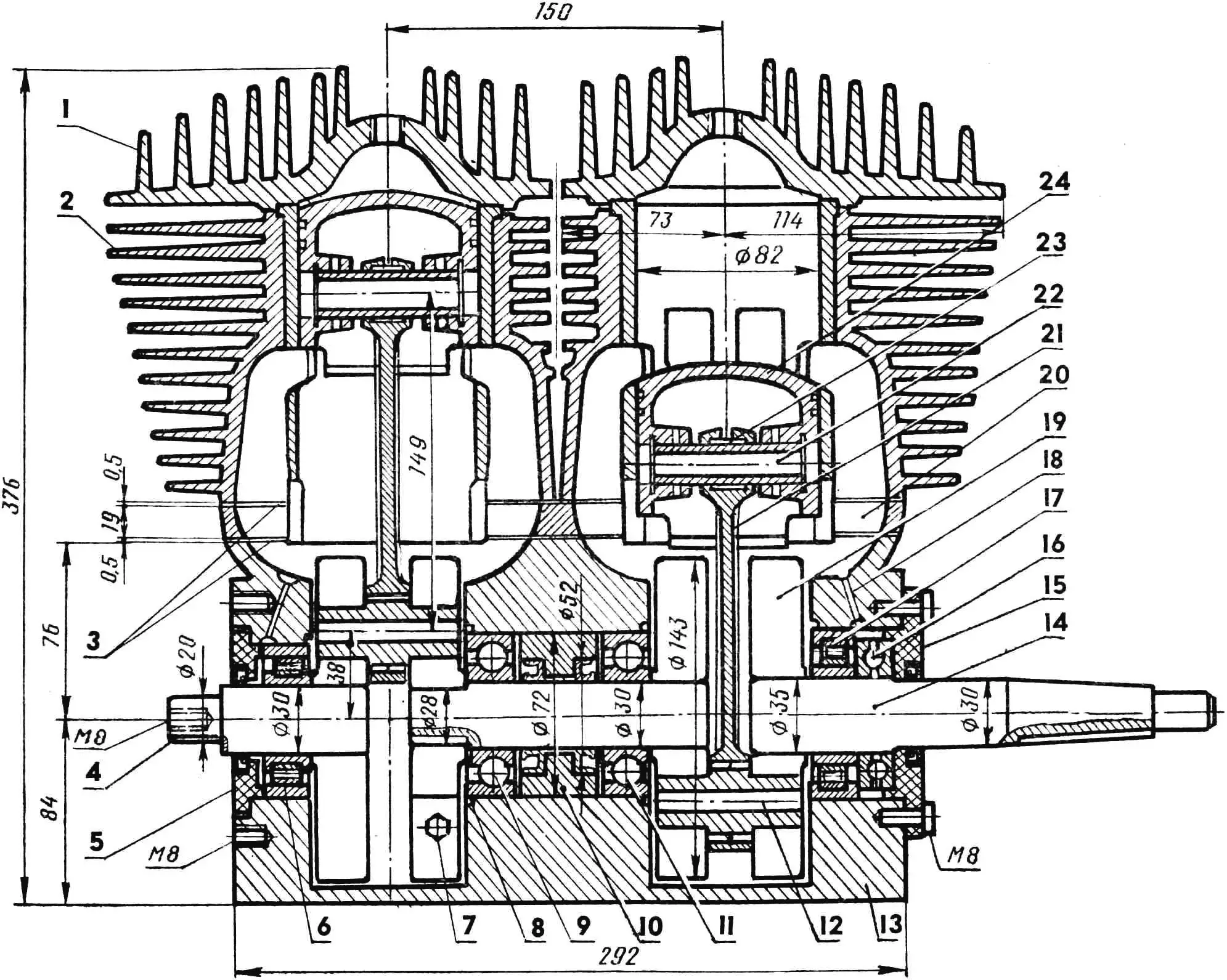
1 — cylinder head, 2 — cylinder, 3 — gasket set, 4 — rear crankshaft journal (standard), 5 — cup with seal, 6 — roller bearing 2306К, 7 — tie bolt of detachable crankshaft parts, 8 — thrust ring, 9, 11 — ball bearings 306К, 10 — inter-chamber spacer bushing with seals, 12 — lower connecting rod pin, 13 — engine crankcase, 14 — front crankshaft journal, 15 — front cup with seal, 16 — thrust bearing 8207, 17 — roller bearing 42207К, 18 — lubrication channel, 19 — crankshaft cheek, 20 — spacer between crankcase and cylinders, 21 — connecting rod, 22 — piston pin, 23 — needle bearing of connecting rod upper end, 24 — piston with two rings.
I want to warn that the engine I developed is not something fundamentally new — it is simply a solid development based on existing motors that have been tested in long-term practice.
I would also like to note that many homebuilders are deterred by the apparent complexity of creating such units as an aircraft engine. I can assure you that an engine of the «Compact-800» type can be built by almost any amateur designer with metalworking skills. Well, and of course, an optimal set of components on the basis of which the engine is assembled. In particular, it is necessary to have a fire engine pump МП-800 (even a non-functional, decommissioned one will do), two crankshafts and two cylinders from the «IZH-Planeta-Sport» motorcycle (hereinafter — IZH-P-S), two «Ikov-34» or «Ikov-36» carburetors with a set of jets from the CZ-400 sports motorcycle (domestic К-62М from IZH-P-S will also work), as well as two pistons with a diameter of 82 mm with rings from the CZ-400 motorcycle.
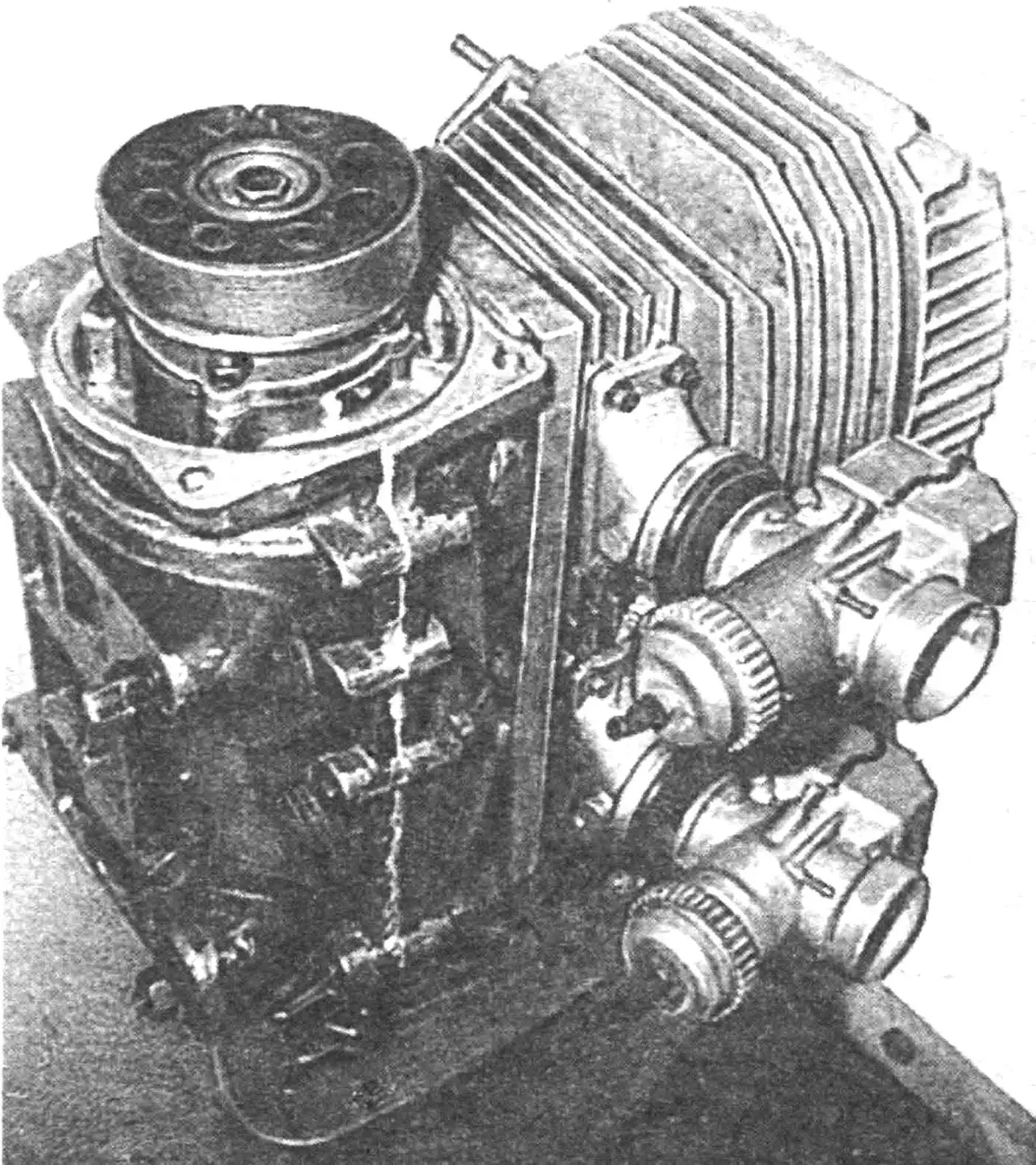
A few words about the technical characteristics of the «Compact-800» engine. This inline two-cylinder two-stroke air-cooled engine weighing 37.6 kg (without carburetors and ignition system) has a displacement of 800 cc, cylinder diameter 82 mm, piston stroke 76 mm, and compression ratio 10.7. Engine power — 70 hp at crankshaft speed 5900…6100 rpm. Fuel — АИ-93 gasoline mixed with 5 percent МС-20 oil. Exhaust using two tuned resonators.
The original cylinders are bored to 82 mm diameter for pistons from CZ-400. During assembly, the adjacent parts of the heads and cylinder fins are milled so that the distance to the milling plane from the cylinder axis is 72 mm.
To prevent turbulence of the fuel-air mixture flow in the engine cylinders and improve their scavenging, the large sphere of the cylinder head must be machined on a lathe (in a four-jaw chuck) to the radius of the piston crown, and the head diameter smoothly reduced to 82 mm. The required compression ratio is selected using a gasket of the required thickness installed between the crankcase and cylinder.
The crankshaft from the МП-800 engine pump, consisting of two cranks with a collet connection in the penultimate crankshaft cheek (on the magneto side), is easily disassembled without damaging the shaft cheeks. I note that the connecting rod stroke of the engine pump does not match the corresponding parameter of IZH-P-S (85 and 76 mm respectively). That is why in the cheeks of the disassembled crankshaft, the standard journals are cut off and new journals made of 40Х steel with an allowance for subsequent machining for bearing fit are press-fitted into their holes (fit — interference press). The old holes of the lower connecting rod pins are carefully welded, if possible — without porosity and foreign inclusions. New holes for the lower connecting rod pin IZH-P-S are machined at a distance of 38 mm from the center of the crankshaft cheek. Both halves of the shaft are assembled separately and processed alternately on a lathe.
The assembled shaft is balanced on straightedges together with pistons, piston rings, and pins. The difference between cylinder sets should be no more than 2…3 g, otherwise increased engine vibration cannot be avoided. Final adjustment during crankshaft balancing is done by drilling holes in the cheeks.
Connecting rods, upper and lower pins with separators were used from the IZH-P-S engine. Pistons with two rings ensure minimal friction of the cylinder-piston pair and reliable engine operation.
The engine crankcase is from the already mentioned engine pump, but its upper half is partially modified. The fact is that the crown height of the CZ-400 piston is 6 mm less than that of IZH-P-S, so 4 mm must be removed from the surface of the upper crankcase cover and the mating plane finished on a lapping plate. It is also necessary to reduce the cylinder height: cut its flange by 2 mm on a lathe.
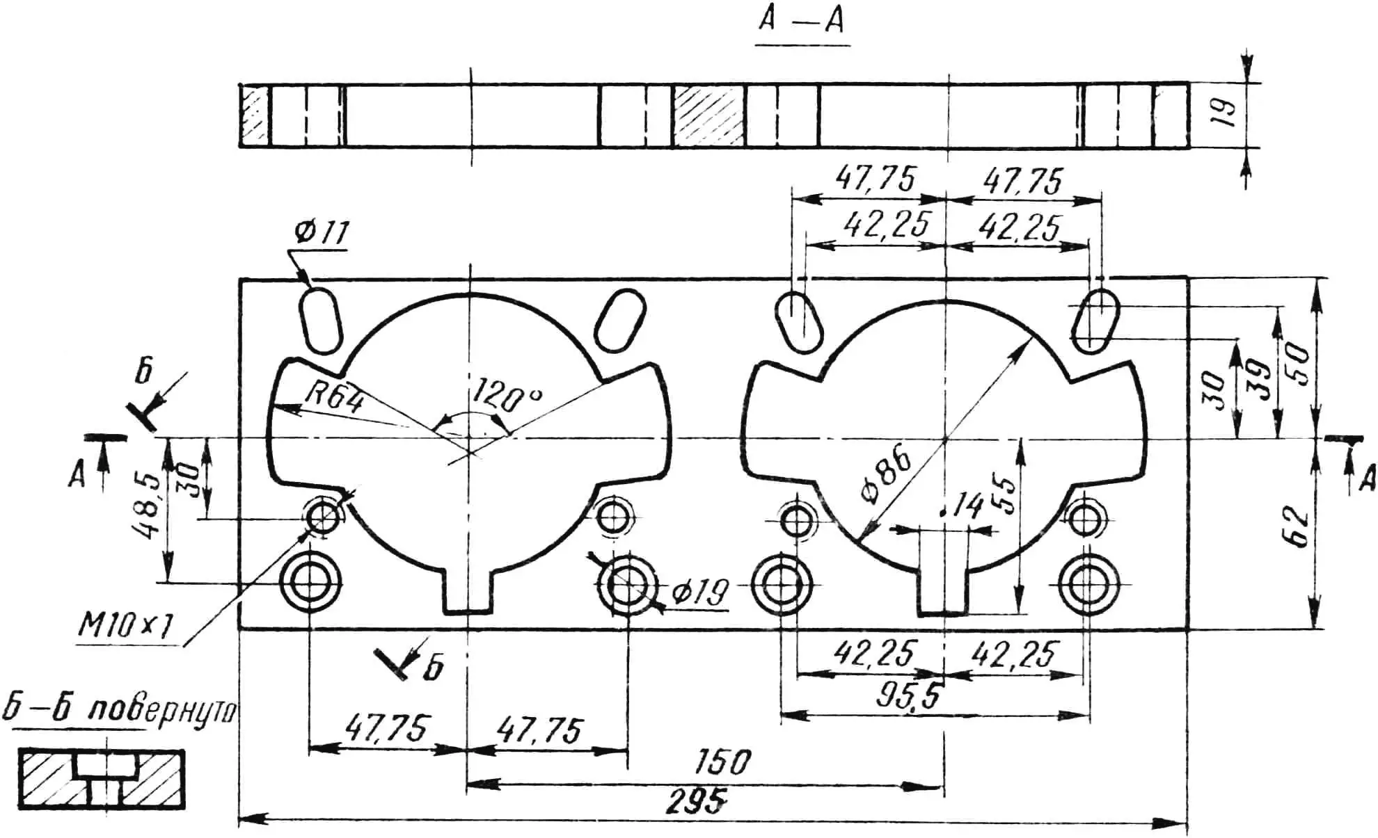
In addition, a duralumin cast spacer must be installed between the upper half of the crankcase and the cylinders, in which holes for cylinder liners and transfer ports are machined, as well as М10×1 mm threaded holes for four cylinder mounting studs according to combined templates taken from the cylinders and crankcase. In the «Compact-800», the spacer thickness together with two paronite gaskets 0.5 mm thick each is 20 mm.
Before boring and finishing the upper crankcase cover, the spacer is secured to it with tie studs. Then, in one setup, holes for cylinder liners are bored in the cover and spacer to a diameter of 86 mm to a depth of 24 mm. Unfortunately, it will not be possible to complete the work of fitting the cylinders into the crankcase (to a depth of 6 mm) using a machine tool due to the fact that perforations are possible in the crankcase in the area of the side transfer ports. Therefore, the cylinders are finally fitted to the crankcase by manual processing. Manual metal removal with subsequent grinding is inevitable when machining smooth contours of transfer ports in the crankcase cover. In this case, it is most convenient to use a reference, which can be an old IZH-P-S engine crankcase.
When manufacturing the crankcase, argon-arc welding can be a good help: with its help, perforations can be eliminated by metal build-up: weld a layer of metal in the transfer port area if perforation is inevitable.
When installing the crankshaft in the crankcase, it should be taken into account that the engine cylinders operate in opposite phases, and the crankcase chamber cavities must be isolated from each other and have no pressure transfer. For this, a standard spacer bushing with two seals inserted into it is installed between the chambers.
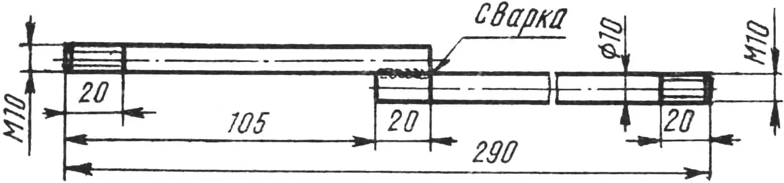
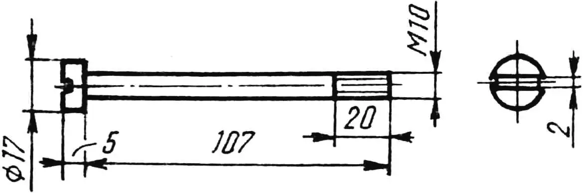
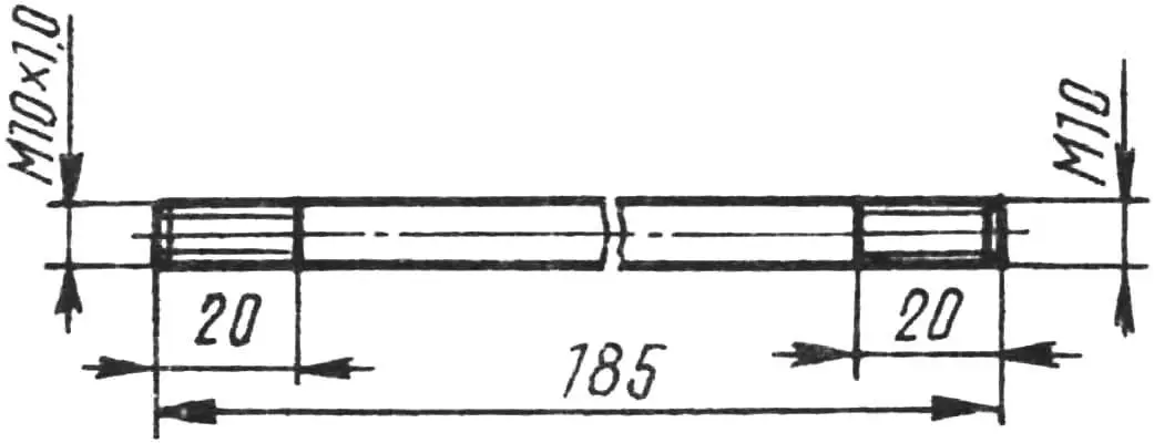
When assembling the engine, four stepped studs (each welded in an overlay from two rods with М10 thread on one end) are screwed tightly into the engine crankcase, oriented so that the cylinders together with heads can be freely fitted onto the crankcase. Then, through a paronite gasket, the spacer is secured to the crankcase using bolts with cylindrical heads «countersunk», and long studs are screwed into the machined М10х1 threaded holes in it, after which the cylinders with heads are mounted and secured with nuts with washers placed under them. The inter-rib bridges on the cylinders must be removed beforehand — this will improve engine cooling.
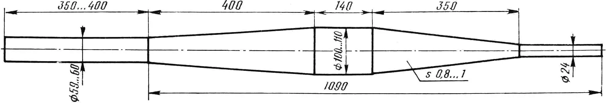
It should be noted that the «Compact-800» develops the above power when working with tuned resonant exhaust pipes, the optimal geometric dimensions of which are shown in one of the figures.
The standard ignition system based on a magneto is unsuitable for an aircraft engine, since a magneto can guarantee a stable and reliable spark at significantly lower speeds than those developed by the «Compact-800». That is why it uses a 12-volt ignition system from the «Jawa» motorcycle. The ignition system parameters (advance, gap between breaker contacts) for each cylinder are set as on a two-cylinder motorcycle — separately for each cylinder.
I note that for an aircraft engine it is desirable to have a dual-spark ignition system (with a pair of spark plugs per cylinder), providing a delay in spark appearance on one of the spark plugs by 4…6 degrees of crankshaft rotation. Of course, when using dual-spark ignition, the energy sources for each of the cylinder spark plugs must be autonomous.
I want to warn enthusiasts trying to increase the power of any motor that falls into their hands at all costs that all possible reasonable measures for this on the «Compact-800» have already been taken, and further engine tuning can lead to a sharp reduction in service life. In particular, the mean effective pressure in the cylinder has been optimized: 6.5 kg/sq.cm. The compression ratio equal to 9.5…10.7 can also be called limiting and maximally beneficial for optimally stable engine operation. I must say that the power of the «Compact-800» is more than sufficient for most amateur aircraft. Here are just a few numerical characteristics showing the capabilities of my motor. So, during bench tests, the peripheral speed of the tips of a one-and-a-half-meter propeller reached 240 m/s. The static thrust at this was 160 kgf, and the propeller efficiency — 67 percent!
If questions arise about the design — write to me at: 624470, Sverdlovsk Region, Severouralsk, Komsomolskaya St., house 37, apartment 115.
«Modelist-Konstruktor» No. 5’95, Viktor DUBROVIN
Recommend to read
 BASKETBALL FOR KIDS
Now, many products — sour cream, cheese, ice cream, are packaged in paper or plastic cups, which after use is discarded. But you can adapt them to any subsidiary. cases, such as for... FROM ICARUS TO THE PRESENT DAY
Dream master the air ocean has long been concerned with humanity. This is reflected in the legends of antiquity, and the works of scientists of antiquity. The mythological wings of...
