 Since the profession of Aviator became popular, there was a need for a training aircraft They were needed for initial pilot training and for maintaining the necessary level of flight training of the personnel of combat units. Since the thirties of the XX century, a whole generation of Soviet pilots passed the initial training on a simple and reliable aircraft Po-2 For advanced training were used Yakovlevskaya UT-1 and UT-2. After the war, under the leadership of Alexander Yakovlev for this purpose has created the Yak-18 and Yak-11.
In the early fifties the mass production of jet aircraft required a revision of the existing system of training of pilots and waiver of initial training on piston machines of the First requests of jet aircraft responded to the Dutch firm “Fokker” it Created a training jet S. 14 “Max-Trainer” made its first flight on may 20, 1950
OKB And Yakovlev, has developed and stockpiled a lot of experience in the development of training aircraft, twice in the early fifties, appealed to the leadership of the air force with proposals to develop jet aircraft initial training in the training of fighters in 1952 from the Yak-17UTI, and in 1955 — from the Yak-23УТИ with a modified engine AM-5 as a result of consideration of these proposals, the air force gave Yakovlev OKB And in 1956 the tactical and technical requirements for jet training aircraft In July 1957 the project of the Yak-104 turbojet R-5-45 was considered by the air force, and in August, the OKB built a model car, However, in connection with the termination of the debugging engine R-5-45 chief designer of the N Mezvrishvili work on it stopped.
Mass production of the MiG-15 and MiG-17 for the arms of the countries of the Warsaw Pact and export to the countries of the “third world” developed not only in Soviet factories, but also on the enterprises of aviation industry of Poland and Czechoslovakia, contributed to the strengthening and further development of national aviation industry of these countries. Along with the license production of Soviet technology, the Polish and Czechoslovak engineers developed original projects of different aircraft, some of them were embodied in metal and commercially available, This experience allowed them to assume ownership of the project development of jet training aircraft.
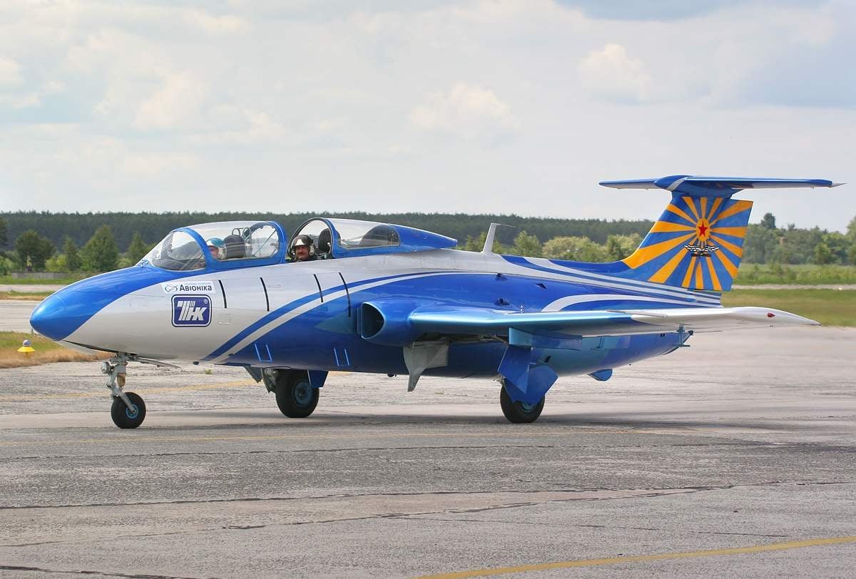
In Czechoslovakia developed jet training aircraft L-29 from the mid-fifties of the last century. It was designed by a team of specialists under the guidance of the famous aircraft designers Zdenek Rublic and Karel Tomas in flight Research and test Institute — VZLU (Vyzkumny a zkusebni letecky ustav), which became in 1954 the Ministry of General machine building of the Czechoslovak Aerodynamic analysis was carried out by the engineers of Joseph hosek and Yang Head When in the early 1960s, Public and Tomas went on a holiday, work on L-29 was headed by a close aide of Rubica Jan Vlcek.
In the first sketches of Rubrica the plane had rednow layout with short, nacelle, fuselage nose section, passing immediately behind the engine nozzle in a neat beam with the tail In the future, the layout of the L-29 acquired classic jet aircraft of that time, with a noticeable impact across many nodes of the airframe, landing gear, hydraulic and pneumatic design solutions produced in Czechoslovakia fighter CS-102 (licensed MiG-15UTI).
This pragmatic borrowing was fully justified the correctness of the decisions taken by the time was confirmed by the release of thousands of machines, perfected technology and years of operation in those conditions for which they were created and L-29, the Designers gave preference to the straight trapezoidal wing with laminar profile and high load-bearing properties, is simple and inexpensive to manufacture To improve the landing characteristics of the wing of the aircraft equipped with slotted flaps, and to reduce the stresses on the control stick when Aileron them performed with axial aerodynamic indemnification Intakes located in the wing roots on both sides of the fuselage on a 50-mm wedges of plum, providing removal of the boundary layer and prevents it from entering the air intake. T-tail was chosen from the conditions of nizatidine stabilizer at high angles of attack and increased efficiency of the vertical stabilizer and rudder at the exit of the corkscrew. In 1956 the development of the L-29 was the planned target and funded by the state.
The problem of Czechoslovakian designers were similar to those that had to deal with OKB As Yakovlev, a Key moment in the creation of a light jet machine was reliable turbojet engines with a takeoff thrust of about 1000 kgs This engine at the enterprises of Czechoslovakia was not designed or produced It had to be created anew, and this required several years. The group of designers VZLU in the head of engineer Rada, which had experience developing a small impeller to drive the winch the aircraft towing targets, start working on the creation of the first Czechoslovak jet engine In early 1956 selected for further work circuit turbojet engine with centrifugal single-stage compressor with seven individual combustion chambers and single-stage axial gas turbine In Czechoslovakia had already issued licenses TRD M-05 and M-06 — analogues of Soviet RD-45F and VK-1. To bench tests of the first pre-production engine, designated the M-701, launched in September 1958 To April 1959, he was tested in all modes and switched to the failover engine on a flying laboratory Il-28 test Program turbojet engine completed by the summer of 1960
In the spring of 1959, built the first prototype XL-29 (registration code OK-70) because of the unavailability of a prototype of the engine M-701 car set serial English TRD “Viper” MK.20 of the company “Armstrong Siddle” static thrust of 795 kgs. April 5, 1959 test pilot VZLU Rudolf Duchon raised to the sky XL-29.
The second airframe is constructed of aircraft used for static strength tests before the first flight of the XL-29 Second flight (the third built) copy XL-29 (registration code OK-14), equipped with engine “Viper”, apparently differed from the first prototype, according to test results OK-70 he changed the shape of the canopy, before the intersection of the vertical and horizontal tail spindle-mounted fairing with electric adjustment for changing the angle of installation of the stabilizer depending on the position of the flaps With the release of brake flaps on the OK-70 was a severe vibration of the tail To eliminate OK-14 changed the contours of the tail section and made in the brake pads 16 via the through-holes On the third flying prototype (registration code 0003, and then OK-02) in June 1960 established the Czechoslovak TRD M-7016, with which he in July 1960 made its first flight that’s when this L-29 for the characteristic profile of the fuselage called a “Dolphin” is the title of the government of Czechoslovakia was officially assigned to aircraft of this type as a trademark in April 1964
The aircraft L-29 aerobatic team “Heavenly knights”. August 2005
At the end of 1959 a competition was announced to develop a unified TCB Warsaw Pact countries In the creative competition was attended by design teams from the USSR, Poland and Czechoslovakia.
In 1957, at the Warsaw Institute of aviation designing a training aircraft TS-11 “Iskra” on the tactical and technical requirements of the command of the Polish air force was headed by Tadeusz plane made debut flights.
The plane was designed for training pilots of fighter and fighter-bomber aircraft, It could be used for flight training in adverse weather conditions, aerobatics group flying, navigation training, working out the elements of aerial combat and destroy ground targets in Parallel with the design of the aircraft started blowing his models in wind tunnels in Poland, and then in the USSR in the range of high subsonic speeds. Conducted flight experiments with model aircraft, attached to the MiG-15bis.
To assess the correctness of the adopted design solutions built a wooden model of TS-11 in full size, who in late 1957 — early.
1958 , the Commission considered the Aircraft had good visibility, the location of the devices on the Board and controls in the cockpit was a logical, rational lighting, all that made me possible pilot error to a minimum the Ease and convenience of access to the basic units can also be considered one of the great advantages of the Polish machine.
In 1958 the group T of the plane made debut flights have proceeded to a detailed design of the machine was based on the four prototype the First of these, made in March.
1959 g, were used for the static test of the Second manned TRD “Viper 8” takeoff thrust 795 kgs, built in December 1959, and February 2.
1960 g test pilot Andrzej Ablamowicz lifted him into the air.
In conjunction with the design TS And Polish designers from the Institute of aviation in 1956 began to develop their own turbojet engines with a takeoff thrust of 1000 kgf Engine received the designation 30-1. During the construction and testing of the prototype engine Polish specialists have faced a number of unforeseen difficulties When it became clear that the development of the jet engine complexity far exceeds the development of the airframe, the designers decided to carry out tests of prototypes of cars with a different engine and the original motor to be installed on production aircraft a Choice of designers fell on TRD BUT-10, intended for other purposes To release technical documentation on the engine started on 1 February 1958 and finished it in July of the same year Technological documentation for TRD BUT-10 and snap-serialized 30 Oct 1958, and the first prototype engine was prepared for testing by December 1, 1959 To June 8.
1961 g the poles built seven prototypes TRD BUT-10.
In March 1961, in Poland, has completed the construction of a third prototype (tail number “03”), and in July — fourth (number “04”) the Second prototype had no weapons, on the third and fourth have two underwing bomb racks, 20-mm cannon and shot-method Prototypes “03” and “04” equipped with the prototype motors BUT-10 with a takeoff thrust of 790 kgs (nominal — 730 kgs and cruising — 650 kgs) In early August 1961, the crew of TS-11 (tail number “03”) composed of engineers Joseph Mineta and Andrzej Abramovich flew to Moscow on the route Warsaw — Minsk — Smolensk — Kubinka — Monino.
Even before the termination of works on fine-tuning the engine R-5-45 Yakovlev, not waiting for new government regulations, addressed to the General constructor To Tumansky to start the initiative to develop a cost-effective engine thrust of 1000 kgf And found understanding with his old friend at the air force Academy in July 1957, the OKB Tumansky With It began to design turbojet RU-19-300 Youth creative team is headed by Yuriy Gusev.
By the time the new government resolution on development of Yak-104 RU-19-300 in July 1958, the work on the engine was already in full swing By this time formed and the appearance of the new turbojet engine thrust at takeoff 900 kgs, compact, with a seven-stage axial compressor and single stage turbine, annular combustion chamber and unregulated nozzle. In the late 1960 engine filed at the state 100-hour bench test that was successfully completed in February this year, the OKB As Yakovlev new engine expected two elegant aircraft the first prototype of the Yak-104, tail number “30” finished in mid-may 1960, and two months later built a second plane with the tail number “50” on the development of training aircraft led by one of the leading specialists of OKB Konstantin Shiyan, worked in this team since its inception At the time he was an active participant in the creation of UT-1 and UT-2, BB-22, the initiator of the creation of the Yak-7, the chief designer of the Yak-18.
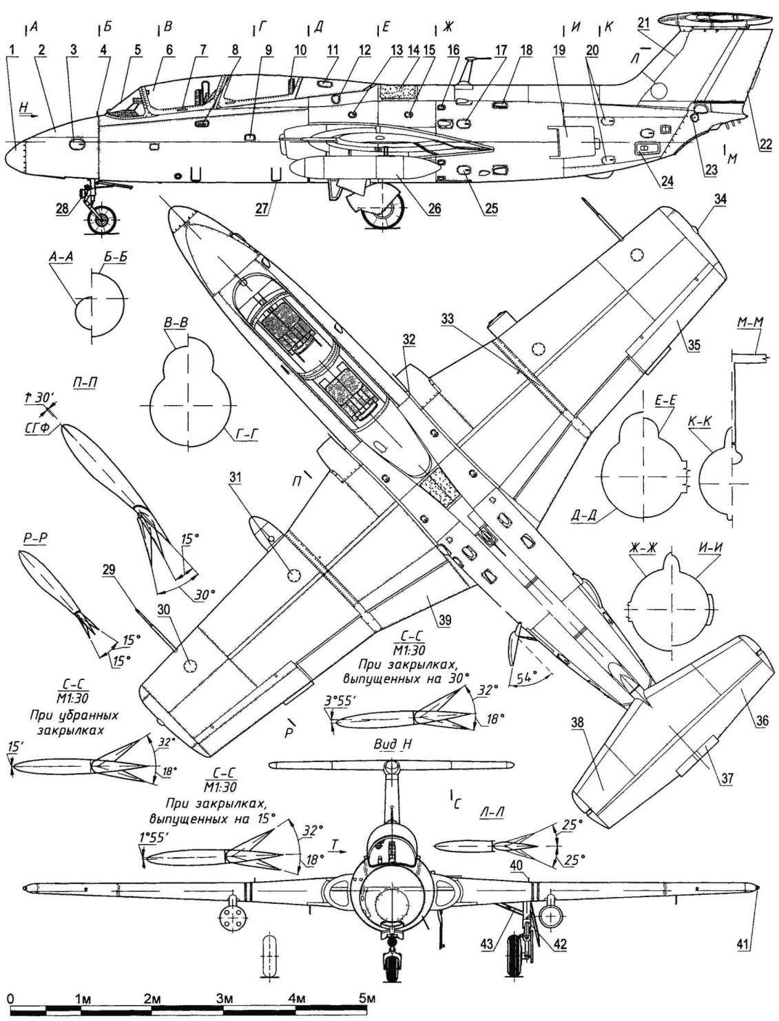
Training aircraft Aero L-29 Delfin:
1 — bow cook, 2 — cover for approach to the battery and oxygen cylinders; 3 — the hatch for filling with oxygen and compressed air 4 — mechanical position indicator nose landing gear, 5 — visor lamp, 6 — hinged to the side of the flashlight first cab, 7 — the handle of the lantern, 8 — arm fixation of the moving parts of the lantern 9 — step with a spring-loaded lid, 10 — ejection seat; 11 — hole for filling with compressed air and check the pressure in the containment system lantern, 12 — manhole cover fuel filler, 13,15 — control hatches, 14 — radio-panel directional antenna of the radio compass, 16 — cover vicenta, 17 — cover flap filling with oil and connect the airfield power supply, 18 — branch pipe of ventilation of the engine compartment, 19 — brake, 20,45 — access doors for checking and replacement of thermocouples, 21 — Kiel, 22 — the rudder 23 — flap approach to the lower node of the hinge of the rudder, 24 — Luc approach to the lower hardpoints flame tube of the engine, 25 — hatch of the engine control and its units, 26 — external fuel tank 27 — bandwagon 28 — taxiway spotlight, 29 — LDPE, 30 hood to eliminate the deviation of the compass and approach to the valve of HPH, 31 — hatch for approach to the bomb racks, 32 — wedge-draining air intake, 33 — a removable cover for the approach to the power cylinders and limit switches flaps, 34 — navigation light (green), 35 — Aileron, 36 — the Elevator, a 37 — trimmer of the Elevator, 38 — adjustable stabilizer 39, the inner section of the flap, 40 — mechanical position indicator main landing gear; 41 — aeronautical fire (red), 42,127 — spring struts, a 43 — breaking down the strut, 44 cassette flares, a 46 — removable covers for the approach to the ports on the system, rocking the aircraft control and manage trimmer, 47 — radio antenna, 48 — cover for approach to the rocking control and filling with slurry, 49,50 — control of access doors, fuel system, 51 — movable part of the lamp, the second car, 52 — intake TRD M-701, 53 — hinge hinge movable part of the lamp first cabin 54 — air intake ventilation first cab; 55 — cover for approach to the nose landing gear, 56 — safety foot, 57 —nozzle for a turbojet engine M-701; 58 — antenna IFF systems; 59-the alarm lamp of the flaps; 60 — button “air Start”, 61,65 — signal lamp, 62 — dashboard, 63 — transparent partition between the cabins, 64 — nozzles ventilating, 66 — pedal foot control, 67 control buttons flaps, 68 and 97 — buttons “Fire”, 69 — cover approach to the launcher panel fuel filters, external connection and drain the slurry, 70 hatch fuel plum, the 71 — cap approach to the rocking control and coupling fitting fuel tanks, 72 — outer section Sariska, 73 — removable part ending with the antenna system of national recognition, 74 hood for the approach to the valve LDPE, 75 — hatches approach to the rocking control, 76 — unit of the NAR, 77 — manhole covers to approach the rocking control; 78 — fold niches main landing gear, 79 — Luc approach to the control horns and connectors systems 80 — radio-panel omnidirectional antenna of the radio compass, 81 — control hatch cover, 82 — fold niche nose landing gear, 83 — landing light, 84 — signal lamp of heating PVD, 85 — handle trimmer of the Elevator 86, the control lever locks the lantern, 87 — left lamp UFO, 88 — rifle sight AS-SNA, 89 — shot-method FKP-22; 90 — magnetic compass LUN-1222 (on aircraft with 15-series), 91 — magnetic compass (for aircraft up to 15-series). 92 — lever emergency brake, 93 — cockpit, radio compass, 94 — main switchboard, 95 switch dangerous height, 96 — box of weapons, 98 — switch on landing lights, 99 — indicator of oxygen, and 100 gauges, brakes, 101 — signal Board, T-9-LUN2841 1, 102 — table of deviation of the direction finder, 103 — altimeters VD-20, 104 — a combination of indexes of speed КУС120,105 — table of deviation of GIK-1, 106 — the artificial horizon AGD-1,107 — indicating magnetic heading PEM-1 heroinusing compass GIK-1 radio compass ark-9, 108 —variometers, 109 — fuel gauge, 110 — tachometers, 111 indicators transtracheal pointer, 112 — a pointer to the height and the pressure drop of the air in the cabin, UITD-15U, 113 — thrust reshuffle “foot control”, 114 — switch “gas Temperature”, 115 — the index of temperature of exhaust gases EGT-1, 116 — clock Achs-1. 117 — turn signal indicator EUP-53, 118 indicator altimeter HC-57, 119 — buttons (switches) the control chassis, 120 — indicating the position of the chassis, 121 radio 122 — the toggle switch control fire alarm, 123 — pointer number M, 124 g — 125 a — white line, 126 — multi-meter, 128 — damper “shimmy”, 129 —pull fold, 130 — nasal non-braking wheel (400×150 mm) 131 — antenna radar altimeter, 132 main brake wheel (600h180 mm) 133 — perforated panel (on airplanes up to 4-series), 134 — tail navigation light (white)
For factory testing of the first prototype began in late may of 1960, a month and a half, 2 July, test pilot OKB Valentin Mukhin for the first time lifted the car into the air And soon to the tests joined the second prototype. In factory tests Yak-30 (the name given to the Yak-104 in 1960) also flew test pilots In P. Smirnov and V. M. Volkov, the car flew test pilots LII and S. N. Anokhin, V. M Pronyakin and A. P. Bogorodsky. The car has received a positive evaluation on each item of the program of factory tests, it is well managed in all range of speeds, easy to perform aerobatics, taking off from soft ground airfields Factory tests Yak-30 was completed in March 1961, but in August 1960 the design Bureau of A. S.Yakovlev passed the car bearing the number “50” on the state tests In January — June 1961, the design Bureau was transferred to the test two prototype aircraft, which took into account comments received in the course of state testing On these machines installed reinforced wing with turbulators to provide a warning of shaking before stalling into the spin, increasing the stability margin for overloading, modified control of the aircraft, cockpit, chassis and a number of other improvements OKB perfectly prepared car to participate in the competition and are expected to succeed.
In early August 1961, the contestants arrived at the airfield near Moscow Monino, the Soviet Union was represented at the competition, the Yak-30 with tail number “90”, Czechoslovakia — L-29 “0003”, Poland TS-11 “03” In August-September 1961 in the air force research Institute conducted a comparative flight tests of all three machines.
Test L-29 was carried out by the test pilot To Podolny and engineer A. D. Osipov, Polish aircraft pilot With In Petrov and the engineer In walk, the Yak-30 — pilot N Sharov and engineer G. V. Puzanov other cars flew hero of the Soviet Union, honored test pilot of the USSR Yu And Antipov and head of A G Terent’ev.
Materials testing for the comparative assessment was prepared by the engineers NII VVS for flight characteristics.Elistratov, strength — N And I. at the power plant — V. J. Panchenkov, equipment — G. A. Imposters on systems — N G goats Coordination of the work was done A f Kotlyar responsible for the preparation of flights and the generalization of the results.
Directly test the L-29 from the air force research Institute was lead by the renowned test pilot Colonel-engineer On N. Yamschikova For twenty-three years of flight operations she has performed more than 8,000 flights, of which 217 combat during the great Patriotic war, has mastered 50 types of aircraft as a lead engineer has tested several prototypes of jet aircraft and a number of tests of production aircraft.
All the planes had engines with about the same thrust, but the mass of empty “Yak” was 1554 kg “Dolphin” — 2364 kg “Sparks” — 2560 kg, respectively, normal takeoff weight of the Yak-30 — 2200 kg, L-29 — 3100 kg, TS-11 — 3243 kg. These parameters significantly affected the flight characteristics of the machines Have a “Yak” the maximum speed amounted to 663 km/h at an altitude of 3 km, the “Dolphin” at that moment, according to the results of factory tests — 598 km/h, “Sparks” — 620 km/h service ceiling the Yak-30 — 14 km, L-29 — 12.1 km, TS-11 — 10 km According to economic indicators the benefits of “Yak” was also there, he was two times cheaper than the “Dolphin” and two and a half times cheaper “Sparks” Operation of the Yak-30 had promised significant advantages: the engine consumed fuel in one and a half times less than “Dolphin”.
When tested in Monino at the plane 1.-29 revealed a number of shortcomings, the most unacceptable and dangerous of which was the delay of the aircraft into a dive while flying at the maximum speed (M = 0,73).
During the competition, arrived in Moscow on an official visit, the President of Czechoslovakia, Antonin Novotny it is likely that in the course of the visit were discussed with the leadership of the Soviet Union the military-technical cooperation between our countries, and in particular on the production of L-29. As a result, in the outcome document of the results of tests of selected Czechoslovak car.
After completion of the competition, the creators of “Dolphin” modified it by eliminating the identified deficiencies, the machines “zero” installation series By the end of 1961 has defined the terms for implementation in serial production of “Dolphins”.
In 1962, the people’s company “Vodochody”, which was part of the Central Bohemian region of the machine-building factories began mass production of “Dolphin” the Plane was appreciated at the International engineering fair in Brno in 1964, was awarded its Gold medal in 1965 awarded the title “the Perfect product of the year”. In 1965 and 1967 the “Dolphin” was the main part of the Czech exposition at the International air show in Le Bourget.
After completion of the contest in Monino further work to test the serial and modified L-29, as well as their military tests instructed leading engineers NII VVS.
O. N. Yamshchikova and A. F. Ivanov and test pilot A. F. Nikolaev, who worked in close contact with the Czechoslovak specialists and aircraft created in this country In the late 1960s to the connected pilot A. P. Holopaw.
Test pilot hero of the Soviet Union Alexander Fedorovich Nikolaev was engaged in test L-29 and its modifications in the air force Institute from 1962 until the end of the service. One of the most difficult work on this plane, made Nikolayev was test L-29 direct and inverted corkscrew.
In flight simulated pilot error leading to a corkscrew, from typical to unlikely in the real world. To facilitate the release of the aircraft from a spin in critical situations under the wings of the plane secured anti-spin rockets, and not once A f, Nikolaev had to use them for successful completion of the flight. Once in the inverted spin has stopped the engine. After the tenth unsuccessful attempt of its launch Alexander F. landed with a dead engine.
The first production L-29 arrived in the Soviet flight school in 1963 their First mastered instructors and cadets of the Chernihiv higher air force school. A group of pilots-instructors and technical specialists have been trained in Czechoslovakia, and then passed on their experience to colleagues. From among the cadets formed a pilot group to learn a new technique.
In the fall of 1963, the air force Institute on the basis of the Chernihiv higher air force school and with the assistance of flight staff the school has carried out military tests “dolphins”. This work led by engineer-Colonel N. Yamschikova.
By the end of 1963 “dolphins” appeared in the training regiments Kaczynski, Kharkiv and Yeisky vvaul, and then in other flight schools in the country. In addition to military academies over time, these aircraft became complete aviation training centers DOSSAF who prepared the air force reserve of pilots and instructors flying clubs DOSAAF operating aircraft.
Pilots making their first steps in the development of the flight profession on this machine was left of her fondest memories.
August 11, 1964 test pilot from the Department of testing, training and sports aircraft, the air force Institute Marina Popovich has performed on “the Dolphin” record flight on the closed triangular 100-km route for aircraft weight 1750 to 3000 kg (according to the classification of the FAI category C-1-d), showing average speed 606,2 km/h.
In addition to the Soviet Union “dolphins” has acquired another 16 countries, Bulgaria, Hungary, Vietnam, GDR, Ghana, Guinea, Egypt, Indonesia, Iraq, Yemen, China, Mali, Nigeria, Romania, Syria and Uganda.
In addition to the basic variant there was two versions of the aircraft.
L-29 1963 — 1966 engineer group B Liston developed on the basis of educational “Dolphin” middle reconnaissance aircraft L-29R, which had a factory code L-329. Under the fuselage in the cockpit area appeared fairing for photographic equipment, and on the ends of consoles additional fuel tanks the Aircraft could be used to conduct aerial tactical reconnaissance in the near front strip a Small amount of L-29R released for the air force Czechoslovakia and Egypt, they were mostly planes 18 series.
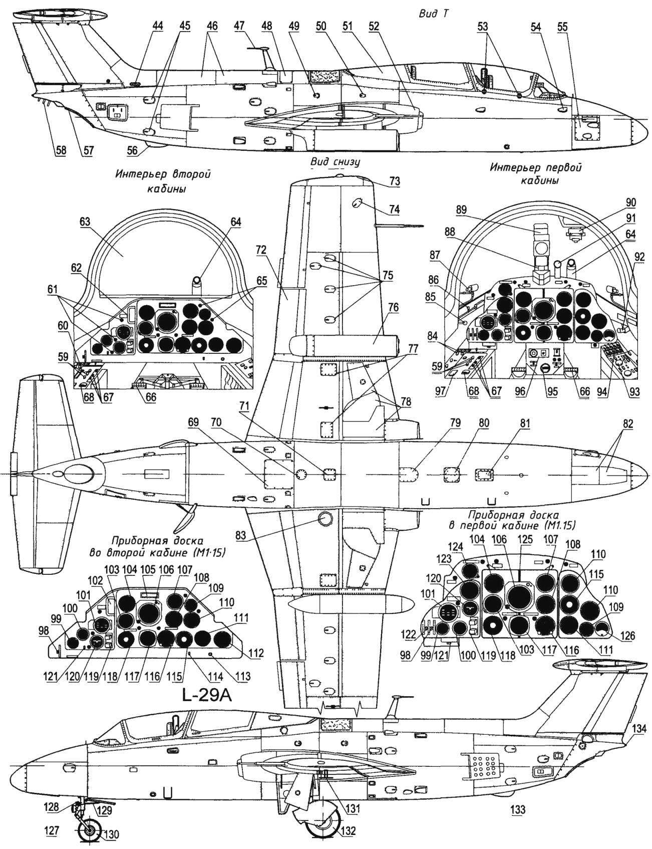
The group of designers of the national enterprise “Aero Vodochody” under the leadership of Jan Vlček, developed the L-29A “Acrobat” (factory code L-429) Aircraft converted from the third plane, the “zero” series, “0003”, participant of the competition in Monino Glazing rear cockpit was replaced with aluminum sheet, but instead of dismantled equipment mounted fuel tank for aerobatics with negative acceleration After completion, the aircraft received the registration number 0517 First took to the air in October 1967 the factory test pilot Juraj Shots.
The aircraft demonstrated good handling qualities. Later this machine received the registration code OK-SZA, it Was built only two such aircraft, both participated in the International engineering fairs 1968 and 1969 in Brno, and 1969 L-29 performed the complex aerobatics at the air show in Le Bourget.
The main characteristics of the aircraft L-29 “Dolphin”
Wing span, m……………………….10,29
Length, m……………………..10,81
The height of the parked aircraft, m 3,13…
Weight, kg
empty aircraft………………………2284
normal takeoff………………..3280
maximum flying………………3540
Fuel, l
in internal tanks………………….1050
in NTB……………………………………….2×150
Just……………………………………….1350
Maximum normal overload without pendants/pendants with a positive…8/7
negative…………………………4/3,5
Maximum speed, km/h at an altitude of 5 km 655…
at sea level (H = 0 km)………….615
Practical range, km………900
The flight duration, h……2,5
The maximum rate of climb, m/min 840…
Practical ceiling, m……………11500
Crew ……………………………..2
Weapons……….200 kg on two suspension units 2 container with 7.62-mm machine guns or 2х100-kg bombs, or 2 units of 55-mm NURSS-5
Recommend to read
 SUPERPLANES MOSCOW MODELERS
The history of the development of the expense of building a traditional class of models of gliders is replete with numerous examples of advances in the field of aerodynamics and design...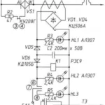 THE FUSE IN THE AC CIRCUIT
Circuit of electronic fuse alternating current, represented in the figure, protects the circuit in which the output is regulated by the triac (or just the triac operates in the mode...
