 Hypersonic rocket plane North American X-15. The construction of the spacecraft reusable type Shuttle “Buran” opened a new Chapter in manned space exploration. The design of this type of device has requested giant engineering research related to the problems that arise when flying at high altitudes and speeds.
In the USA such studies began in the fall of 1945, when details 100 German V-2 rocket (A-4) was delivered in the United States. The first rocket was launched on 10 may 1946 and reached an altitude of 112 km. within 1947, the laboratory of space medicine was first launched a few missiles with plants and insects on Board with the purpose of studying the effects on them of radiation, and then with the mice and monkeys. However, the percentage of successful launches and returns to earth put the objects were small, and the time spent instrument bays of missiles at high altitudes. Studies of the upper atmosphere using rockets were very intense until the mid 50-ies. But despite this the atmosphere above 50 km was still the least explored area.
For obtaining the missing information would be manned aircraft. But the cars with jet engines was not raised to such a height, and a pilot raketoplana of Bell machines X-1 and X-2 rocket engines reached only 35-kilometer mark.
In 1954, NASA has ended the development of requirements for the new missile and aircraft designed to study heights of 50 to 100 km and a flight speed of up to 7200 km/h. To achieve such performance required a rocket engine with a thrust of about 27 tons. During the tests it was planned to obtain data that could be used in the construction of military suborbital apparatus Dyna-Soar. Equally important was to obtain information on aerodynamic heating, heat resistance of structures, the characteristics of the throttled rocket engine, providing the conditions of life and cosmic radiation in the upper atmosphere. It was also expected to use the new aircraft for geophysical research. The experimental aircraft was given the designation X-15.
Previous models of experimental rocket planes Bell X-1 Bell X-2 was launched from a modified b-29 bomber at an altitude of about 10,000 m at flight speed of the carrier 240 km/h More severe X-15 decided to start with the jet bomber b-52, which allowed to increase the height of the launch and the flight speed at the time of start of the rocket plane.
The x-15 hung on a special pylon under the right wing of the bomber, between the engine and the fuselage. This required a careful study of the aerodynamics of such a coupling and the starting flight path aircraft X-15. In addition, the suspension X-15 under wing included the presence of a pilot in a rocket plane to start taxiing, whereas when testing the X-1 and X-2 pilot passed from the bomb Bay of the carrier rocket only upon reaching a predetermined height. This scheme is the suspension of the X-15 required the development of methods for the safe ejection of the pilot in case of emergency, which would allow him not to touch while the front edge of the wing, the aircraft carrier and its huge keel. On the fuselage of the bomber set blister for observations and multiple cameras to film and photography, the X-15.
In December 1955, the North American firm was given an order to build three copies of the plane X-15. Rocket engine XLR-99-RM-1 (fuel — ammonia oxidizer — liquid oxygen) with a maximum thrust in space 27 t was supposed to provide a firm Reaction Motors. When the construction of the first instance of the aircraft was nearing its end, the engine has not worked. They had to install a X-15 two motors XLR-11 with four combustion chambers, used as oxidizer liquid oxygen and alcohol fuel blend.
The first experimental rocket plane X-15 after its official release on 15 October 1958 he was transferred to the test Department the North American. The construction of the second finished in March, and the third in August 1959. The third machine is a rocket engine XLR-99-RM-1 has temporarily mounted it to the layout.
The design of the rocket was calculated to work at temperatures up to 650 °C and is basically a monocoque or semi-monocoque, alloy steel, Nickel alloy of “Inconel X” and titanium. In the fore part of the fuselage was sealed compartment with double shell, which housed the pilot and the equipment. The outer covering was made of “Inconel X”, supporting frames made from titanium alloy, and inner cladding made from aluminum.
The Central part of the fuselage was formed is located ahead of the wing tank for the oxidizer, the fuel tank and the frames, which is attached to the wing. The main construction material is “Inconel X”. It was performed end wall tanks, and interior partitions — aluminium alloys.
To the rear fuselage of “Inconel X” from the supporting structure of a titanium alloy of the tail was attached, the chassis and engine. Wing mnogopikselnoy design with ribs at the tip and tail. The front and rear spars had flat wall, supported by rifts, mid spars were corrugated walls. Panel wing skin thickness 0.6 to 1.2 mm was performed using a machining of “Inconel X” and had a welded-on scope cover. Frame and ribs of titanium alloy.
Horizontal and vertical tail was dvuhkonturniy coffered beams, reinforced with ribs. To wear wings, and also in the toes of horizontal and vertical plumage were divided into separate compartments of the heat-absorbing elements from “Inconel X”. The fairings on the side of the fuselage housed control cables, pipelines, hydraulic systems and electrical wiring devices. To reduce thermal stresses in the aircraft structure, the X-15 was widely used corrugated elements.
Chassis tricycle, with front bow support; consisted of a two-wheeled front rack, in front of the cockpit, and the two main stands. The latter was equipped with steel skis, which were in flight in the retracted position. Produced chassis under the action of gravity and air loads. The skis were mounted on rigid stands with air-oil shock absorbers attached to the upper parts of the stands, which provided some freedom when the chassis is loaded with the weight of the aircraft. Cleaned chassis ground manually.
Horizontal tail provide both longitudinal and lateral control. Course control was carried out by two rotary fins, arranged on the top and bottom of the fuselage. The lower keel was dumped before landing and descended by parachute; after the restoration it could be used again. In the vacuum of space, the rocket plane was controlled jet nozzles located in the forward fuselage and on the wing. The automatic control system on the X-15 had had only the damping.
The rocket plane had a unique control system with three knobs. Central — traditional, it was used in normal flight modes. Two side handles with armrests was used for control in flight with large longitudinal and vertical overloads, when the mass of the hands of the pilot could lead to unintended deflection of the Central control knob. Handle reactive control systems were located on the left console in the cockpit, and the handle control of aerodynamic surfaces on the right panel. Pilot R. white in flight in which he reached a height of 66 m 140 operated a rocket plane X-15 by using only the side knobs. The first attempt to do in flight without a Central control stick was almost led to the loss of the rocket plane, as the maximum speed of deflection of the stabilizer, constituting 15 deg/sec, was small for planting. After that, the control system has been tweaked and the rate of deflection increased to 25 deg/sec.
The pilot of the rocket plane was wearing a sealed suit, ventilated and naduvanii nitrogen. In case of pressure drop in cabin pressurization of the suit corresponds to the pressure at an altitude of 10 700 m. Nitrogen that enters the suit, which was heated using a small electric heater.
There were difficulties with fixation of the head of the pilot, which operated in flight threat overload, forward and down. To avoid the trauma, the designers were supposed to attach the helmet to the headrest with a rope, but then on the canopy made a special emphasis to the frontal part of the helmet that held the pilot’s head from moving forward.
To prevent icing and fogging of the windshield of the canopy into the space between the panes of glazing was supplied heated nitrogen and, in addition, the inner panel had electric heating. Windshield when entering the atmosphere can heat up to vishneveckogo color, so that the cooling system of the cabin had to work flawlessly.
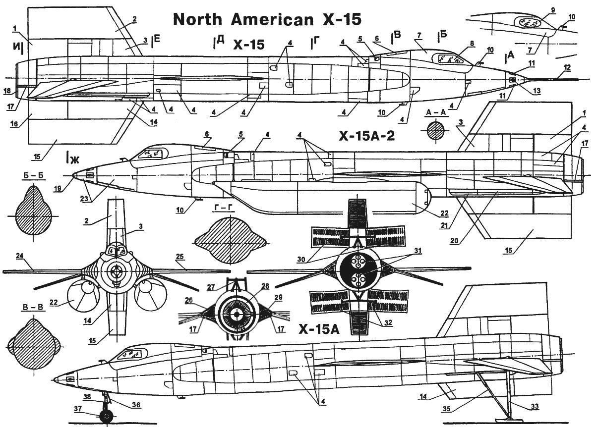
Experimental hypersonic rocket plane North American X-15:
1 — top air brake; 2 — upper rudder; 3 — upper keel; 4 maintenance access holes; 5 — camera; 6 — hatch the outside of the compartment; 7 — the cockpit canopy; 8 — glass canopy made of heat-resistant glass (early version); 9 — glass canopy made of heat-resistant glass (late version); 10 — antenna radio altimeter; 11 — nozzle ballistic control system pitch; 12 — remote rod LDPE; 13 — nozzle ballistic control system at the rate of; 14 — lower keel; 15 we dropped lower the rudder; 16 — lower air brakes; 17 — pipe of discharge of hydrogen peroxide; 18 — flame tube; 19 receiver air pressure (late version); 20 — the tail landing gear in the retracted position; 21,34 — ski tail stands in the retracted position; 22 — additional jettison external fuel tanks; 23 — heat resistant coating; 24 — right wing of the plane; 25 — left wing of the plane; 26 — the influx of the fuselage; 27 — the mechanism of the brake flaps; 28 — LRE Reaction Motors XLR-99; 29 — fuel tap; 30 — the flaps of the upper air brakes in the released position; 31 — LRE Reaction Motors XLR-1l-RM-5; 32 — the bottom flaps are air brakes in the released position; 33-the tail landing gear is in the released position; 35 — struts tail landing gear; 36 — plate niche nose landing gear; 37 — tubeless tires with nylon ply; 38 — nose strut; 39 —left swivel stabilizer-elevon; 40 — the flap of the left wing of the plane; 41 — panel wing skin; 42 — nozzle ballistic system roll control; 43 — monolithic front edge of the wing; 44 — fuel tank filler hydraulic; 45 — stabilizing keels; 46 — strand shoulder strap; 47 — control system aerodynamic control at high accelerations; 48 — suit, “Clark MS-2”; 49 — remote jet control system at high accelerations; the 50 — handle of the emergency release foot; 51 — mounting feet; a 52 — flap from a supersonic air flow; 53 — stabilizing telescopic rod; 54 — oxygen tank; 55 — armrest; 56 — handle reactive control system at high accelerations; 57 — dashboard; 58 — handle aerodynamic control system for large overloads; 59 — stick control when flying at low speeds; 60 — Nickel tubes with ceramic coating; 61 — protect from the flame; 62 camera with a constant traction; 63 — pump liquid oxygen; 64 — inlet nozzle for liquid oxygen; 65 — the gas generator running on hydrogen peroxide; 66 — the exhaust pipe of the turbine; 67 — control box; 68 — outlet hole; 69 — the outlet of the turbopump; 70 — fold niches of the front wheel (drawn inside of the fuselage)
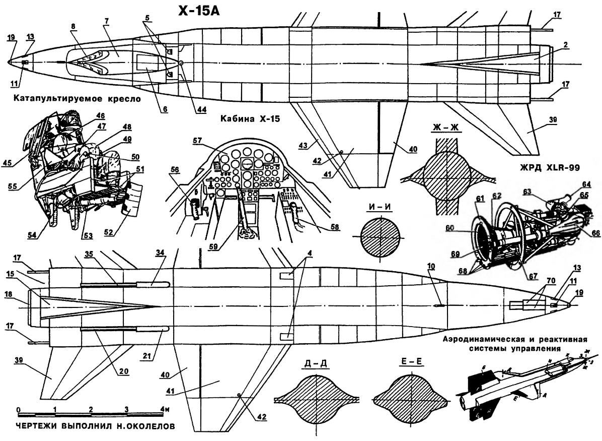
Refer to the diagram “Aerodynamic and jet control system” rocket plane X-15:
A — elevons; B — upper rudder; In — bottom steering wheel; air brakes; D — nozzle control roll; E is the landing flaps; F — nozzle control the pitch; Z — nozzle control course; And tanks with hydrogen peroxide for a ballistic control system; — handle
Ejection seat pilot provided a safe escape from the cabin if the flight speed of up to 4000 km/h and at altitudes of up to 36 500 m at any position of the aircraft in space. The seat is also provided rescue pilot at low altitudes at a speed not more than 170 km/h. the Bailout was made with the help of a powder charge, stabilizing fins and beams was put forward automatically. With the release and lifting either of the two special arms dropped the lantern, then joined catapult seat mechanism.
The rocket plane X-15 at the handling characteristics are like fighters, “hundredth” series, which had greater vertical rate of descent during landing and changing balance in the transonic regime of flight. The pilots described the X-15 as a typical aircraft with high aerodynamic quality, its characteristics of stability and controllability are not inferior to the high-speed fighters of the time.
For training future pilots the X-15 used the F-104. The plane with the air brakes released and the engine idling, could quite accurately reproduce the landing performance of the rocket plane X-15. The aerodynamic quality of the aircraft if the flight speed of 550 km/h was almost the same. On the X-15, the flaps and landing gear are usually issued after the alignment, and to reproduce the behavior of the rocket on the F-104 had to put the flaps in takeoff position and to release the chassis long before the glide path. Before each flight the X-15 pilots trained in the implementation of approaches on the F-104 in the area of lake Rogers and all the spare landing pad.
Initially scheduled first flight with the included power plant in February 1959. However, on 19 March 1959 was only the flight of the carrier with suspended to it the X-15. When this was discovered a small problem with the communications system and the electrical system. Was only successful test of the system draining the fuel, which was tested using dyed liquid. During the second flight, the connection was also lost, and the third was observed a problem with the auxiliary engines of the rocket.
The first free flight of X-15 took place on 8 June 1959. The rocket separated from the carrier aircraft at an altitude of 11 600 m at a speed of 830 km/h. the Pilot performed a series of smooth maneuvers (in particular, “eight”) to test the effectiveness of the control flaps. Ventral keel was dropped almost before boarding. During alignment when landing, the plane made a number of longitudinal vibrations, especially caused by the pilot to test the effectiveness of management. The speed at touchdown was 288 km/h. the path Length 1400 m.
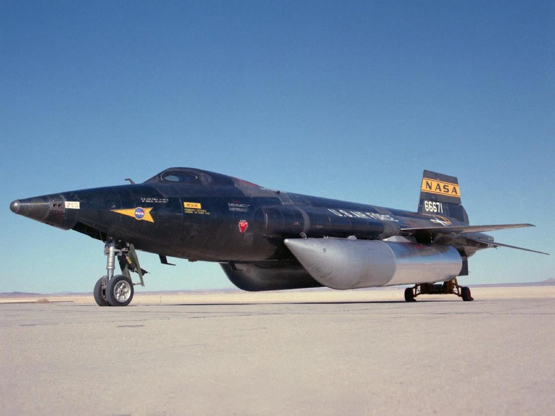
Unlike raketoplana the Bell X-1 and X-2, podeshevevshih in the bomb Bay of the aircraft b-29, X-15 were fixed on the media under the right wing and when released is blown asymmetrically, thus obtaining a roll to the right with the transition into a dive. Therefore, the pilots before the separation of the rocket from the carrier rejected the ailerons to the left for 6 to 8° to reduce the threat roll. The most difficult part of the X-15 flew for 0.8 sec; leaving the zone of turbulence b-52, it had a roll of 20°. It was not easy and the pilots of the media, who constantly complained about the difficulty of taking off and landing without flaps, which prevented the suspended X-15. Because of the large difference in the masses of the b-52 and X-15 rocket plane separation had little impact on the media. The mass of the b-52 with hung X-15 at takeoff was about 135 t At the time of separation at an altitude of 13,000 m the total mass was equal to 118 million tonnes, of which the share of the X-15 had 15.4 tons To facilitate balancing in the left wing of the aircraft b-52 refueled more fuel than the right side.
Because during takeoff, climb and flight of the launch site to evaporate a significant amount of liquid oxygen from the tank to the X-15, b-52, there were two tanks with this oxidizing agent, one of which with a capacity of 3800 liters was used to refill tanks at cruising mode, and the second with a capacity of 1,900 liters — on the mode up. The supply of oxidizer b-52 was enough for a joint two-hour flight.
The first free flight of a rocket plane with the engine running was held on 17 September 1959. After separation from the carrier at an altitude of 11 600 m X-15 reached a height of 15 000 m and 10 minutes later landed. Second flight with the engine running after two delays for technical reasons, took place October 17, 1959: X-15 separated from the b-52 at an altitude of about 12 500 m and reached a height of 18 000 m. In flight was achieved the speed of about 2250-2400 km/h. the flight Duration was approximately 10 minutes. The plane landed on the bottom of the dry lake Rogers, approximately 105 km North-East of Los Angeles, the landing speed was in this 320 km/h.
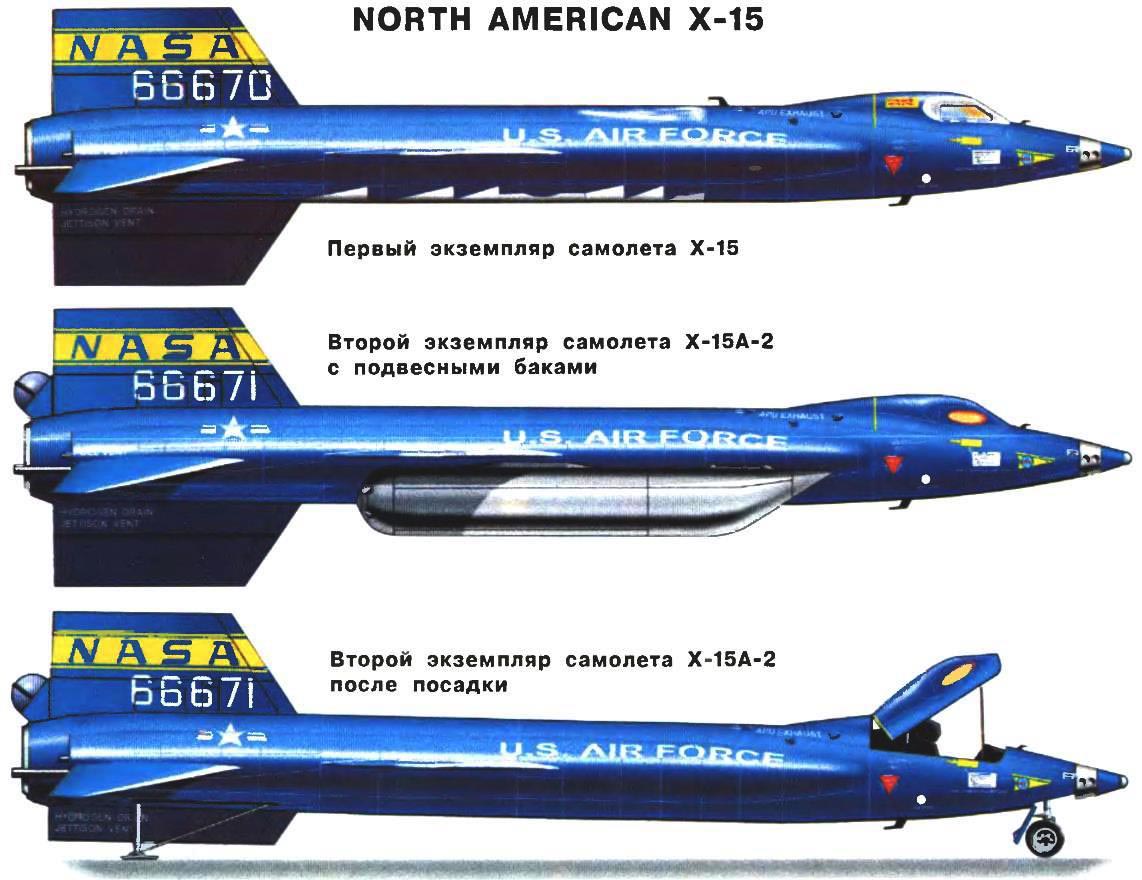
In the early 1960 started flying, the second missile X-15. At the same time changed and the shape of the nose of the aircraft. Instead of needle-like she was stupid. At the tip mounted spherical sensor for hypersonic flow stabilization system.
By mid-November 1961, two X-15 made 77 flights, including 44 with included LRE, 29 flights a low-power rocket engine with two XLR-11 and 15 flight with new XLR-99, with a thrust of 25.8 t 33 aircraft are not separated from the carrier b-52 or in accordance with the task, either due to a failure (communication failure, containment system, auxiliary power unit, control system, etc.). First flight with rocket engine the XLR-99 was made November 15, 1960, two years later than foreseen in the plan, because of the difficulties in fine-tuning the engine.
The entire flight test program the X-15 consisted of two parts — the flight for maximum speed and flight to maximum altitude. The result of the first part was the achievement of 9 November 1961, the second rocket speed 6548 km/h at an altitude of 30 km.
The second phase of the programme was initiated in April 1962, after changing the shape of the glazing plane with rectangular to oval. Two flights in the right pane of windshield glazing cracks due to temperature stresses during reentry. After the alterations 17 July 1962, he took flight in which the rocket plane X-15 reached an altitude of 107 906 m. All the pilots who flew the X-15 in the second part of the research, he received the title of pilot-astronaut of the US. The first astronaut was R. white, and the last — John.Walker (he later on the F-104 crashed into the experimental-70).
All record flights took place at approximately the same plan. X-15 was dropped from media at a speed of 900 km/h at an altitude of about 13 500 m. After separation from the b-52 and the engine is running, the pilot was given “gas” and kept the angle of attack of 8°, until the plane goes into a climb with a predetermined angle (for example, for a flight at an altitude of 7500 m this angle was 30°), then before shutting off the engine was kept constant pitch angle. The engine was switched off after 90 s after launch at a speed of 1900 m/s at a height of 48 km. Then the plane flew on a ballistic trajectory with an angle of attack equal to zero. At this time the pilot was in a state of weightlessness. The duration of the period of weightlessness of about 2.5 min. the entrance to the dense layers of the atmosphere occurred with the angle of attack of about 15°, which was attached to the aircraft at an altitude of 60 km.
Experimental hypersonic aircraft NORTH AMERICAN X-15
In 1962 a second rocket plane X-15 upgraded. To increase the duration of the flight with the engine up to 150 since it was equipped with two drop tanks with fuel and oxidant total capacity 6123 L. the First flight of the upgraded X-15A-2 made 28 June 1964.
About a third of all flights are made under conditions when fully, or partially denied stabilization system relative to one of the axes. In some cases, the flights were made despite the fact that it was known in advance about such failure. Their main reason was a problem with the electrical wiring and electronic Assembly unit manual installation gear ratios.
In high-altitude flights were failures of the system pressurization. Once in flight with a speed of 5500 km/h at an altitude of 30 500 meters started to smolder paint inside the cabin, so much so that the smoke made it difficult for the pilot review.
During the program flight test of the rocket occurred and three major accidents. First — November 5, 1959, while flying the second instance of the X-15. Due to the explosion of the lower engine XLR-11 and the beginning of the fire the pilot was forced to turn off the engine and land. Since the fuel was blended at the time of descent of the aircraft on a steep trajectory, it could not drain completely, and landing weight of the rocket plane was more than acceptable. With a quick release nose landing gear the shock absorber foamed the oil and upon contact of the front wheel with the ground isolator did not work, the fuselage behind the cabin was deformed, and its lower surface was in contact with the ground. X-15 was able to be repaired, strengthened fuselage additional plates (top and bottom) in place of bending. The same change was made to the design of the other two aircraft. In addition, modified chassis.
The second accident occurred on 7 June 1960 as a result of an explosion during ground tests of rocket engine YLR-99, which was caused by excessive pressurization of the tank with liquid ammonia due to freezing of the regulator and safety valve. To prevent the recurrence of similar incidents, the boost regulator the fuel tank was modified and installed in a warmer place. Also modified the safety valve and the piping system to drop the pressure. The tail section of the damaged plane was completely replaced, and the forward fuselage was restored, eliminating significant damage.
The third accident where a third plane made an emergency landing and overturned, occurred on 9 November 1962. After separation from the carrier and start the engine as a result of the failure of the diode and transformer in the system the fuel pump control engine thrust has fallen to 30 percent of the maximum. The engine had shut down, and the pilot began to lower the machine to fit into the spare area. Before landing the pilot wanted to lower the flaps, but the flap control has not worked. After landing at low vertical speed, approximately at the time when the nose wheel touched the ground, the left main landing gear strut was broken, the X-15 was escapetravel and crashed.
Flying the X-15 ceased in February 1968. All was done 191 flight. The first instance of the machine is transferred to the national aerospace Museum, the second at the air force Museum in Dayton.
Flight performance of a hypersonic experimental rocket plane NORTH AMERICAN X-15:
Wingspan, mm…………………………………………………………………………………………………….. 6700
Length, mm…………………………………………………………………………………………………………….. 12 240
Height, mm………………………………………………………………………………………………………………4100
Wing area, м2…………………………………………………………………………………………………. 18,58
Empty weight, kg……………………………………………………………………………………………………. 7765
The weight of fuel in internal tanks, kg…………………………………………………………………… 8300
Normal takeoff weight, kg………………………………………………………………………………14 190
Maximum speed, km/h………………………………………………………………………………….. 7200
The estimated maximum flight altitude, m……………………………………………………………. 76 200
The maximum flight range, km…………………………………………………………………………..450
N. Food reserve was, A. CHECHIN, Kharkov
Recommend to read
 NEW “DRESS” OF THE WALLS
Apartment repair is troublesome and expensive. To such conclusion came anyone who has ever experienced this "natural disaster". The following tips are addressed to the homeowners... CARATASCA
Of course, it is easier to nail to the box or similar container with two ends of the handle and carry it like a stretcher — but it's the two of us. And if you have to work alone? Then...
