
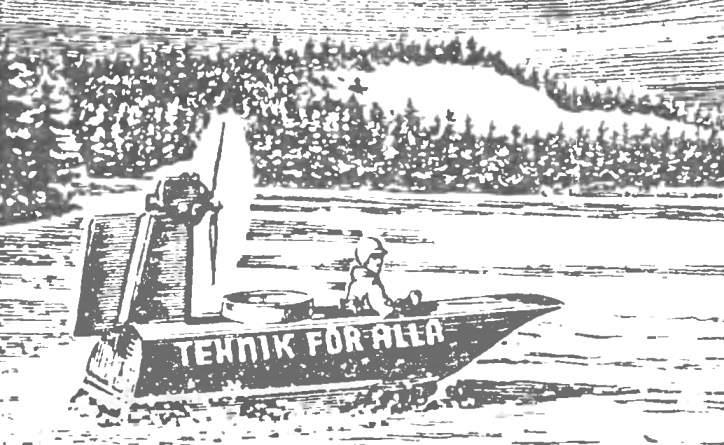
 In our magazine in 1973 (No. 2 cover No. 3, 4, and 6 — description and recommendations) we talked about the boat “TFA” air cushion, created by Swedish designer, Amateur Cumbersom Gustavson. The publication aroused the interest of many readers.
At their request we inform you about further work on the modifications to this boat. The article is based on material from the Swedish magazine “Techniques for Alla” (“Technique”).
Boat “TCA” at the present time has undergone significant structural changes. Initially it as the sustainer of the power plant used engine at 25 HP, He was placed on a special pole at the top. Homemade propeller was fitted directly to the shank of the crankshaft. Such motor installation did not have any defects and ensured the necessary tests of the boats in the conditions of different speeds and capacity, allowed us to determine the maneuverability and stability of the machine.
However, there are also disadvantages: somewhat high center of gravity, difficulties with the installation of the safety devices of the propeller. Sparked criticism from the technical inspection and a home-made propeller. Him as a full guarantee of security demanded factory ID: propeller to provide the necessary tensile strength at high revs, must be designed and manufactured by highly qualified.
All this made the author’s design to create a different, cheaper, more reliable engine installation. Here are some of its characteristics.
Fans. Instead of self-made propeller for the sustainer motor installation it was decided to use two fans standard construction V-belt drive. The designer found it possible to significantly lower the engine and lower the center of gravity of the whole machine.
Following the safety regulations set by the British (as no other regulations for these machines does not currently exist), the author refused to use fans made of cast light alloy. As shown by sad experience, these fans at high rpm, there were cases of breakage of the blades or their partial failure.
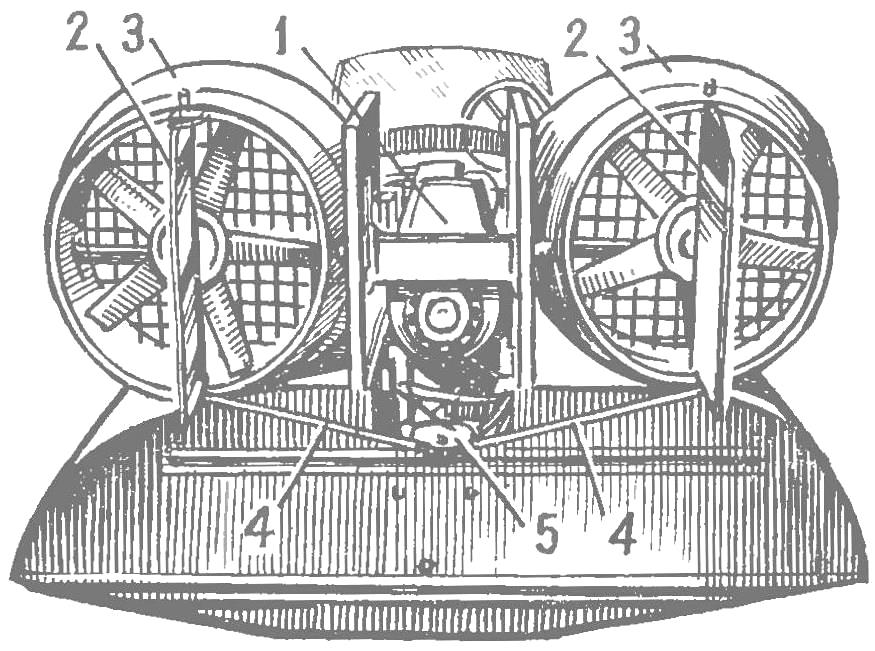
Fig. 1. General view of propeller installation stern:
1 — engine “Lloyd” 24 l S., 2-2 air rudders, 3-3 — aerodynamic ring, 4-4 — rods, 5 — steering pulley.
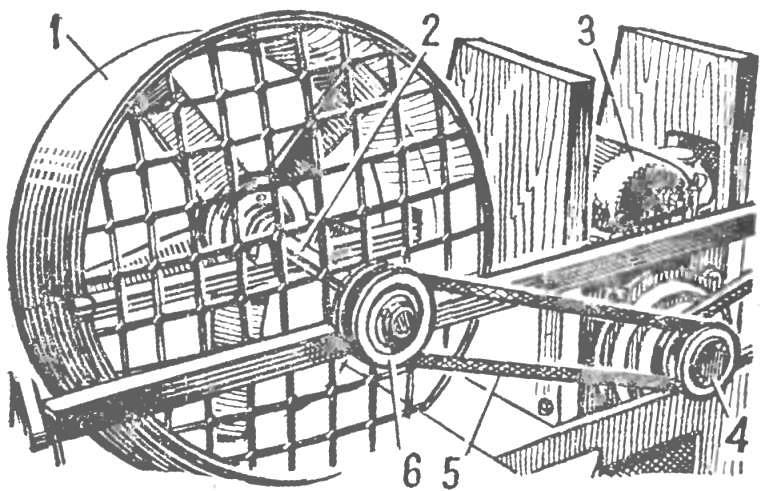
Fig. 2. Propeller installation (front view):
1 — aerodynamic ring, 2 — shaft fan, 3 engine, “Lloyd”, 4 — a double pulley on the motor shaft, 5 — extropy timing belt, 6 — pulley on the shaft of the fan.
Therefore, the selected fan of the Danish production model is “Multi-Wing” with half-sleeve from the silumin and plastic sheet. Such fans were easier to get, they are cheaper and more reliable.
It should be noted that the efficiency of the fan is slightly lower than that of the propeller. However, if the fan is to provide an aerodynamic ring, its effectiveness increases significantly.
New March installation (Fig. 1) consists of a two-cylinder internal combustion engine working on two-stroke cycle.
Engine “Lloyd” has an output of 24 HP at 4500 rpm. It is placed at the center of the machine, at the bottom, between the two fire bulkheads that are formed by struts of the pylon. The weight of the engine together with the starting device, the new mount and other items amounted to about 30 kg, which is significantly less weight the previous engine. From V-belt pulley, placed on the dowel on the shank of the crankshaft, the transmission to the two fan belts is carried out (Fig. 2).
Impeller fans are mounted on the shafts, resting on hard-bearing and supporting bearings mounted on transverse beams. I-beam steel, of square cross-section pipes. They take the load from the fan, passing it on the hull of the boat.
The fans of brand “Multi-Wing” have five blades with a diameter of about 600 mm, installation angle 45°. They are placed in the aerodynamic rings, made of fiberglass with exterior plywood plates. The presence of these rings have resulted in more efficient fan operation and compliance with safety requirements for their protection. On the input side of the rings are installed to ensure the safety of a metal grille. On the output of the parts are steering wheels. Every fan at 4500 rpm consumes power up to 12 HP
Has undergone changes and motor installation, creating an air cushion under the boat (Fig. 3). Used two-stroke engine “Villiers” with the volume of cylinder 175 cm3, developing 8 HP, instead of the previously used with a power of 10 HP per shank of a crankshaft of the engine “Villiers” attached shestilopastnye fan “Multi-Wing” with a diameter of 600 mm, the installation angle of 35°. Together with the engine they are placed in the mine, which is a aerodynamic shaped ring, made of fiberglass plastic. Ring security top is covered by a protective grid of synthetic wire Ø 5 mm.
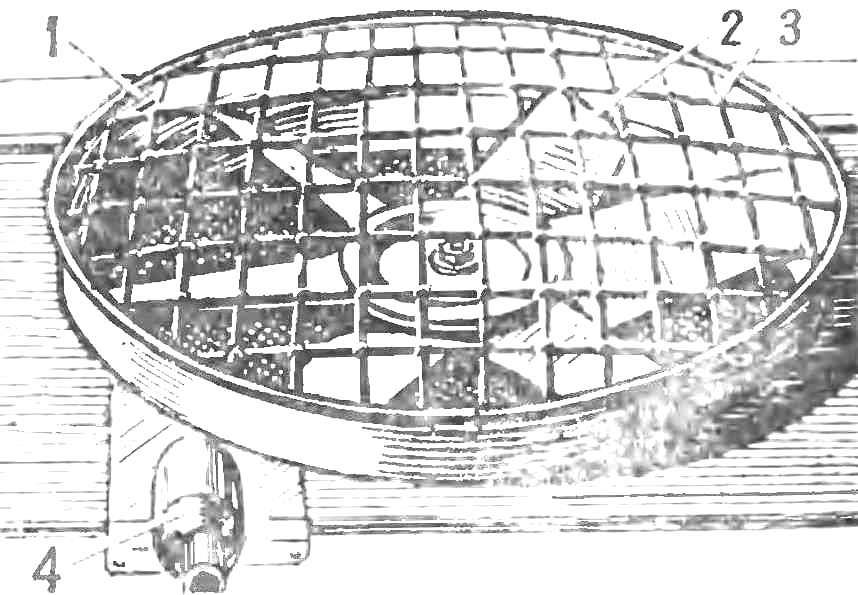
Fig. 3. Upgraded fan airbag:
1 — suction ring, 2 — impeller, 3 — protective grille made of synthetic wire Ø 5 mm, 4 — engine exhaust pipe
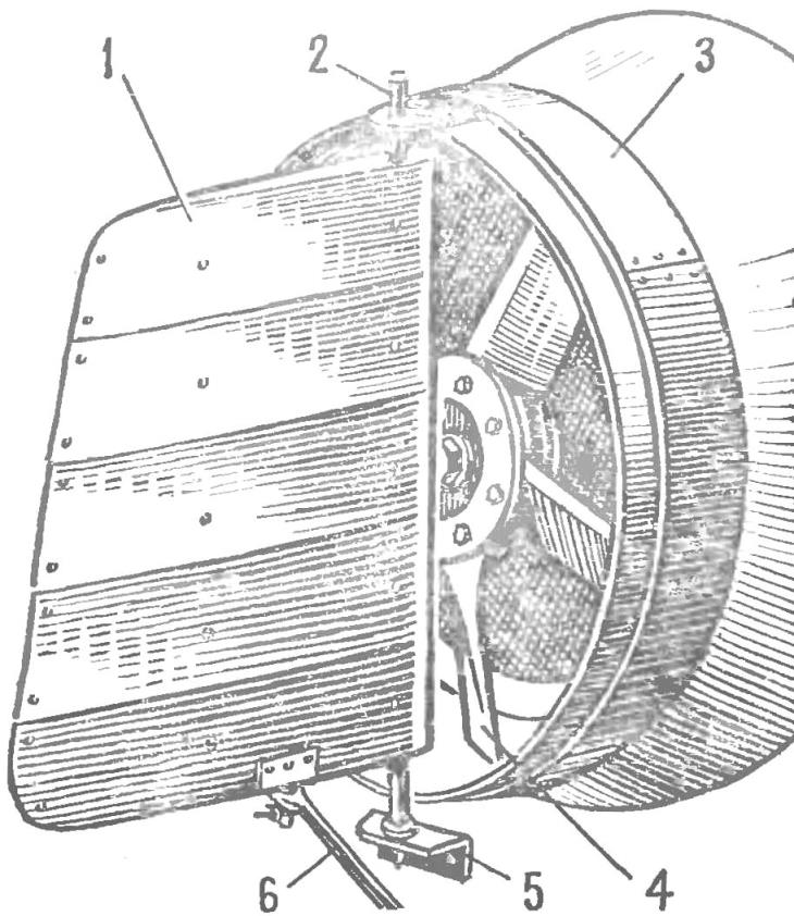
Fig. 4. Steering gear new design:
1 — rudder, 2 — upper semi-axis, 3 — aerodynamic ring, 4 — fan, 5 — mounting lower driveshaft, 6 — tie-rod
Management. Changing the direction of movement of the boat by two air rudders located on the rings directly behind the impeller fan. The rudders at the same time provide sufficient protection, limiting the ability of the approach to the fans in the back. Handlebars bent of duralumin plates with a thickness of 0.5 mm, mounted on the axial tube Ø 15 mm.
The connection plates, and fastening — rivets. At the bottom of the rudder, between the sheets of sheathing located nodes to which from the Central of the video-rocking fit traction control (Fig. 4). From the control panel in the cockpit and up to roller rockers transmission remained unchanged (it was done with ropes).
Due to the fact that a modified engine installation turned out slightly lighter than the preceding, to provide the required pitch (i.e. the alignment of the machine) the battery was rotated to the rear. Changed and fuel system, previously consisting of two separate tanks for each engine, as the latter worked on different grades of fuel.
The modification has one tank, on the flange which is placed an electric pump providing power to two pipelines at the same time. After refitting the boat “TFA” was lower, although his body has not changed.
LITERATURE ON THE COURTS HOVERCRAFT:
Benoit Y. Y. N. Kursanov M., hovercrafts. L., Sudpromgiz, 1962.
Nikolaev N. I. Flying a Rover. M., Voenizdat, 1963.
Adasinsky S. A., Shuttle car, air podushke. M., “Nouna”, 1964.
Rugini E. I., Air, all-terrain vehicles. M., “Engineering”, 1964.
Semenov E. V., and Air vehicles. M., Izd-vo DOSAAF. 1967.
Pavlov A. I., Puzyrev M. N. Hovering above the wave — single and double SVP. A collection of “Boats and yachts”, № 3 (43), 1973.
Recommend to read
 MOTORCYCLE ON FOUR WHEELS
The idea is to build a ATV (four wheel motorcycle) developed a long time — needed equipment by means of which the trolley with a load of shabby, fishing for the easy road to go, and just... WITH THE ENGINE OF THE SCOOTER
The tillers built by members of the circle "Young technician" vocational school № 25 of the city of Tartus. With it treated potato plots, mow the grass, carrying cargo. The...
