Upon completion of flight tests of the first prototype version remade on the model of serial machines I. was transferred to the West coast of the USA in the squadron VF-5S. In the summer of 1936, this fighter participated in secret experiments on the use of powerful light sources to reduce visibility of the aircraft in the air. During the tests, the most dark areas under the wings, stabilizer and fuselage were covered with a special headlight, which should make the plane a uniformly illuminated and therefore less noticeable on the background of the bright sky. However, the system of “light camouflage” showed no value, and in the autumn of 1936, the experiments stopped.
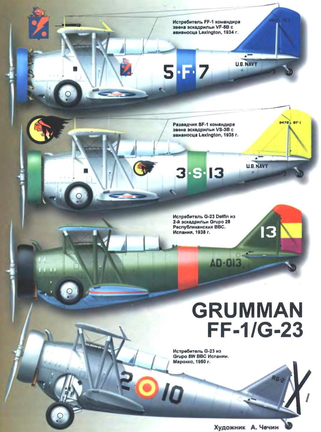
Deliveries of production aircraft began in April and ended in November 1933. Twenty-five fighters were in squadron VF-5B of the USS Lexington, and one aircraft was sent to VF-1B at the air base, Anacostia. In the early winter of 1935, the squadron VF-5B was moved to the aircraft carrier Ranger, from the deck of which FF-1 flew until 1936, until they were replaced by the F3F. Despite a number of shortcomings, aircraft FF 1, get a pilots nickname “Fi-Fi”, left a good impression.
After the withdrawal of the FF-1 from the composition of the carrier-based aircraft 22 cars overtaken at the state aircraft factory of the Navy in Philadelphia to rework them in training. The aircraft received the designation FF-2. They filmed the landing hooks and sets additional control in the second cabin. All exhaust pipes have combined into a single manifold outlet exhaust gases down so they do not fall into the cabin.
All FF-2 were distributed on the backing parts of the Navy and marine corps, where he served for training naval pilots. Weapons from aircraft is not removed. Some FF-2 installed radio compass with rope antenna strung between consoles upper and lower wing.
By June 1940 in the parts there are only 15 serviceable aircraft, and in December 1941 — only seven. Latest FF-2 was written off for scrap in July 1942.
Scout SF-1
Even during the construction of the first prototype fighter FF-1, the Navy ordered a reconnaissance modification under the designation XSF-1 design made minor changes. So, to increase range installed additional fuel tank for 170,3 l (instead of one of the guns). The car was equipped with an engine WRIGHT R-1820-78, the width of the ring Townend was increased, which positively affected the aerodynamics of the fuselage.
The first reconnaissance flight took place on 20 August 1932 and 10 days later it was sent to the base, Anacostia, which immediately began receiving flight tests. After their successful completion of Vieg ordered 34 aircraft SF-1. In the design of serial machines has made several changes relating to propulsion, aerodynamics and control systems. Individual exhaust pipes of the cylinders was replaced with a common exhaust manifold. To reduce the drag of the external weight compensators ailerons replaced the internal. And adjustable stabilizer, switched to SF-1 from fighter, was fixed. After all these modifications the maximum burst speed of scouts made up of 331.5 km/h, 8 km/h faster than the FF-1.
The first SF-1 the customer handed over on 15 February 1934. Last, 34-car, left the firm Grumman as a test sample the following modifications under the designation XSF-2. From the resulting aircraft, the sailors formed one reconnaissance squadron VS-3B, based in Lexington, and the remaining seven aircraft were assigned to seven different deck units. It was five fighter and two bomber squadrons. At the end of 1935 SF-1 withdrew from combat units and transferred to the coastal base in the part of the Navy reserve and the marine corps.
The prototype aircraft XSF-2
Left on the plant the last serial sample SF-1 was fitted with powertrain from the fighter, the F2F-1. To do this, the nose of a scout remade and closed the hood (from the fighter). The aim of these works was, rather, the desire to unify propulsion carrier-based aircraft. Engine PRATT & WHITNEY R-1535-72 TWIN WASP from F2F developed a capacity of only 650 HP, but had a significantly smaller diameter — this gave hope, that the decreasing speed of the XSF-2 will not be too significant.
The aircraft made its first flight on 26 November 1934 and showed a maximum speed of 325 km/h. Military experts considered it insufficient, and the test program was discontinued. In 1940, the airframe of the machine was transferred to the school of Junior aviation mechanics as tutorials.
Scout-bomber XSBF-1
In 1934, Wieg announced a competition to create a new carrier-based scout-bomber. The competition was attended by seven firms. Five of them presented a draft monoplanes firm Brewster — XSBA-1, Hall — HRTV-2, Northrop — HVT-1, the Douglas XTBD-1 and the Vought — XSB2U-1. And firms Curtiss and Grumman biplanes proposed XSBC-3 and XSBF-1.
The basis of the XSBF-1 by the designers of the firm Grumman laid the technical solutions tested on the scout XSF-2. In the beginning of 1935 was completed the construction of the prototype with the engine PRATT & WHITNEY R-1535-72 TWIN WASP, and the new variable-pitch propeller, which gave the aircraft a maximum speed of 346 km/h its a major increase happened due to the improving aerodynamics. Armament consisted of two machine guns (one could shoot forward, the other back) under the fuselage can be suspended 227-kg bomb.
Tests revealed no special superiority of the aircraft over a biplane of the Curtiss company, and the development of monoplanes was somewhat delayed. So the Navy decided to adopt the aircraft, under the designation of the Curtiss SBC-3 A XSBF-1 was on the basis of Anacostia and has been used for testing various avionics. In the summer of 1939 the car was written off for scrap
Advertising GG-1
When the firm made up of serial production of aircraft FF-1 and SF-1, the factory still had a number of details and spare parts of these machines. The management has decided to collect from them a special machine for advertising flights. The aircraft received the designation GG-1 and the civil registration number X12V Its first flight took place on 28 September 1934. Being assembled from parts, GG-1 differed from the FF-1 and SF-1 brand new nose which housed the engine PRATT & WHITNEY R-1340 power 350 HP
After Assembly, the car was painted red and called the Red Ship (the red ship). Until 1936, the firm used the Grumman aircraft at various public events. During one of the demonstration flights GG-1 interested in the famous canadian pilot, athlete and entrepreneur Howard Klein, who expect to earn on export of aircraft equipment to Latin America. Being the official representative of the canadian firm Canadian SAG & Foundry he signed a contract for the licensed production of fighters FF-1 in Canada under the designation G-23. In accordance with the contract, the firm Grumman was to supply finished parts for final Assembly of the machines on the production lines in Fort William, Ontario.
After negotiations with the leadership of the company Klein bought the plane as a prototype G-23. In October 1936, the firm has restored GG-1 to the factory to rework on the standard G-23. Him put a new engine WRIGHT R-1820-F52 power 890 HP with the latest variable-pitch propeller and returned to the place of the standard canopy from the FF-1.
20 Nov 1936, Howard Klein surpassed the updated GG-1 in Montreal, but on 15 December he had to return to the States to demonstrate the aircraft to representatives of the Commission on the arms procurement of the government of the Spanish Republic, which wanted to buy 16 fighter G-23.
In March 1937, Klein went to the GG-1 in a promotional tour. March 17, 1937, he arrived in Mexico, and then flew to Nicaragua. 29 September 1937 tour suddenly interrupted: GG 1 fell into the sea due to running out of fuel near San Juan Del Norte failed to reach the coast of Nicaragua a few miles.
Fighter G-23
In the summer of 1936 to Canada profit components for Assembly of the first series of fighter — Grumman sent 52 of the fuselage tail wings 66 and 70 sets of wings, and some parts made firm, Brewster. From GG-1 aircraft differed engine WRIGHT R-1820-F52 capacity of 890 HP, the cylinder covering ring Townend was increased to 457 mm chord. The motor rotates a variable-pitch propeller Hamilton Standard company. Small arms match the fighter FF-1. In addition, under the wing can be suspended two 50-kg bombs
As a result of the flight of the Klein government of Nicaragua bought in Canada one instance of G-23. Another car was sold to Japan Republican Spain, who showed great interest in G-23, could not buy the planes directly, bypassing the agreements between the countries of the so-called “Committee on non-intervention”. So the Republicans have decided to place a dummy order for 50 fighters, supposedly originating from Turkey. The first 34 aircraft in a disassembled state, three ships were sent to “Turkey” on 2 April 1938. When it came time for the last batch of 16 cars, the deception was discovered, the fighters returned to the factory in Fort William. One of these planes managed to sell in Mexico, and the rest of the Klein tried to “attach” in Canada.
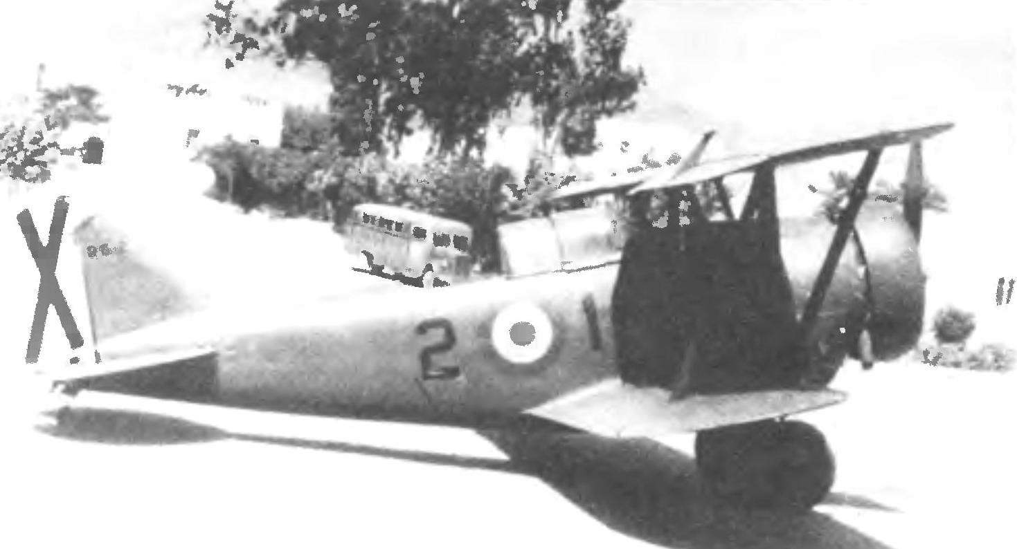
Fighter G-23 Spanish air force
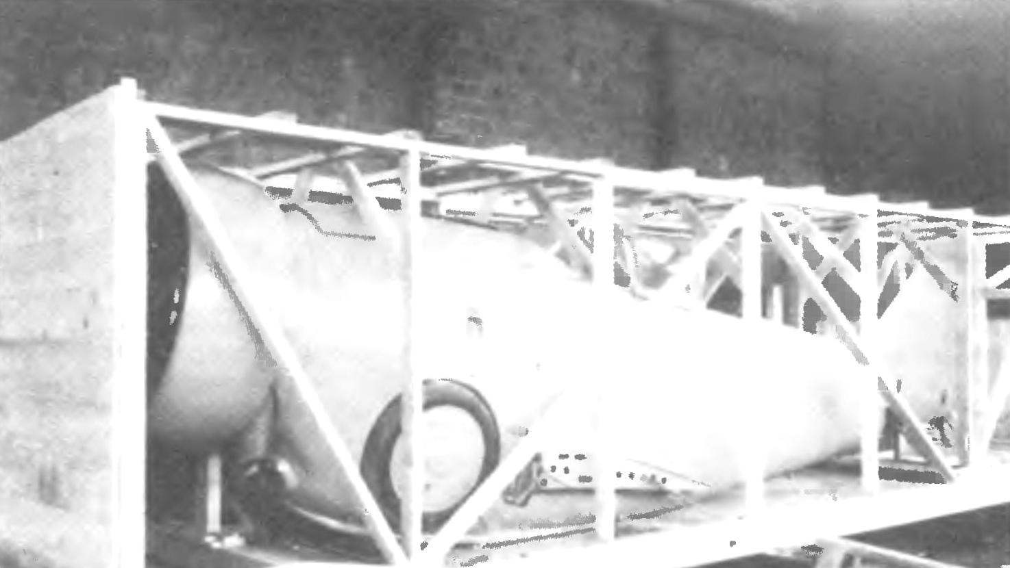
Fighter G-23 packaged for sending to Spain
However, the canadian air force were reluctant to adopt outdated aircraft G-23 and under various pretexts evaded negotiations with the firm Canadian Car & Foundry. Nevertheless, in September 1939, after the outbreak of war in Europe, the Royal canadian air force (RCAF) decided to purchase a G-23 for use in aerial patrols of coastal waters.
In December 1940, 15 G-23, named Goblin, arrived for duty in the 118-squadron RCAF in Rockliff, Ontario. In the harsh canadian climate, “goblins” showed itself with the worst hand. To raise all the planes in the air was only after the end of winter. Full combat readiness of the squadron had reached only the middle of June 1941.
12 December 1941 G-23 was officially removed from service and replaced with a fighter P-40. Five planes left for training flights, but after one of the pilots was nearly poisoned with exhaust gases, flying goblins banned.
Combat use of the G-23 in Spain
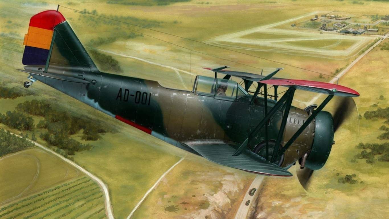
Thirty-four G-23 arrived to Spain through France in the spring of 1938. After you build and fly them, became part of Grupo 28, which consisted of two squadrons. The first was commanded by captain Santiago Capillas, and the second captain Diego Sanchez. With an eye on the marine origin, the Spaniards christened the aircraft the name DELFIN. Dolphins are inferior to the fighters of nationalists, and their main task was to be the attacks on ground targets.
Three aircraft of the first squadron sent under Truel, ten flew into the area of the river Ebro, and the second squadron, at full strength acted in Andalusia. The combat debut of the G-23 was a complete failure. Two biplane made a forced landing in enemy territory and was captured by the nationalists. Before the summer of the Republican offensive in the area of the Ebro river dolphins have not done anything outstanding, although intensively flew in Valencia, patrolling the coastal strip and conducting air defense of Cartagena. No downed enemy aircraft on account of the Spaniards did not appear.
In August, nine G-23 flew in Extremadura in Western Spain for air support of ground forces. At this time the nationalists failed to win air superiority, which immediately reflected on the losses of the Republican aircraft. September 1, 1938, a pair of G-23 was found in the air with the “Fiats” CR-32 from Grupo 2-G-3. As a result of transient fight G-23 was shot down. For the period August 1938 to January 1939, the Republicans lost eight dolphins: one in the accident, two destroyed on the airfield, two kills and four aircraft were captured on the ground.
In March, the remaining G-23 was transferred to Cartagena. The civil war was over, the aircraft of the Republicans was almost defeated, but this war period was the most successful fighter G-23: one of the pilots managed to shoot down a German seaplane Non-59V. On March 22, five dolphins, and twenty-15 has carried out attacks on the Italian landing ships trying to enter the Harbor of Cartagena, and caused serious damage to the aggressor. 6 Feb latest the loss of dolphins has become a G-23 Diego Sanchez, shot down a German Bf-109E. On 30 March, after the capitulation of the Republicans, five G-23 flew to Algeria, where the Spaniards asked for political asylum.
Of the 24 aircraft G-23, available from the Republicans, 23 were lost: 3 of the machines were downed in aerial combat, 10 were victims of air strikes or accidents, 6 went to the nationalists and 5 were the French in Algeria, which after a while brought them back to Spain. The remaining 9 aircraft Franco was accepted into service under the designation R. 6 and included part of Grupo 5W stationed in Spanish Morocco. The planes were used as training machines, and some specimens have reached 1955.
To this day preserved only one copy of the G-23. This car has been sold in Nicaragua, and in 1942, after the cancellation, she was cast in the terminal area of Managua. In 1961, spraying chemicals cornfield, the American pilot John Simons saw an abandoned and partially destroyed glider G-23. Having bought the remnants of the fighter, Simons over four years to restore a biplane to flying condition, and in February 1966 surpassed it in the United States. The only difference restored aircraft from the original is its powerplant. Instead of an engine R-1820 Simmons had to put the engine R-1340 and a three-bladed propeller. The rest of the fighter is authentic. Firm Grumman bought the rarity and repainted it under carrier-based fighter FF-1 of squadron VF-5B Red Rippers, put him in the National aviation Museum of the US Navy.
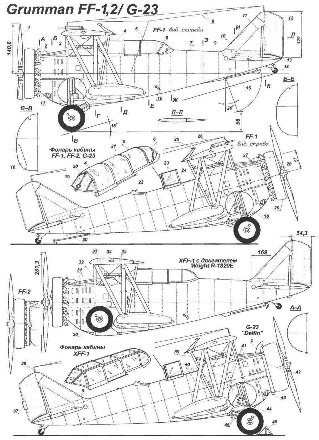
Design description
The plane FF-1 was a double-a single-engine biplane of mixed construction with semi-monocoque all-metal fuselage, fabric covering of the wing and retractable landing gear.
The fuselage — semi-monocoque. His force consisted of 14 frames and supporting stringers and spars of power. Fuselage is dural completely. Panel covering a compartment of the engine, was mounted on a slotted locks with push the head of the FAE. On the panels that covered the box of the engine, had slits for discharging the cooling air.
In the forward fuselage on Motorama of steel pipes mounted engine. Engine mount installed on the first power of the frames. To it was attached the mechanism of the landing gear. Between the first and second power formers were located the oil and the main fuel tank. The sides, bottom, in the hull, were arranged round cutouts, which retracted main landing gear. The second power frame performed the functions of a fire wall separating the cockpit from the engine compartment.
The cockpit was closed the transparent canopy, consisting of six sections. The last section of two bent sheets of plexiglass — could emerge. The pilots seat was made of duralumin, they didn’t have breezeno and not regulated on height.
In front of the cabin were fixed optical sight of the type Mk.ll, and below equipped with two 7.62-mm machine gun. For cabin hand set radio station. On some aircraft installed radio, antenna which was strung between the upper and lower wing. In the same compartment was located electrochrome distribution, on-Board first aid kit, emergency fresh water supply and bortac. In the rear fuselage mounted brake hook and a retractable tail wheel, and tail control.
Power set of the wing dural with pressed ribs; the second and third force the frames is attached to the lower wing. The whole surface of the latter had a fabric covering. The mechanization of the wing was absent. Ailerons with fabric covering was located only on the upper wing and had a hard drive, and external aerodynamic compensation for reduced effort on the control handle.
The upper and lower wings between a connected N-shaped braces; the first, moreover, was attached to the additional struts to the fuselage and concealed in their lanes! and two inflatable rubber bag to maintain buoyancy after a forced landing on the water.
The tail Assembly was an all-metal power set. The fin and stabilizer were dural covering and rudders and height and fabric. Stabilizer with adjustable angle setting from -10 to +5 degrees, driven by a knob on the left panel of the front cockpit. Rudders — flexible cable. To ensure greater rigidity of the stabilizer and fin were joined together by a profiled strut.
Landing device consisted of a retractable tailwheel landing gear and landing hook. The system of harvesting and the landing gear is hydraulic, with possibility of emergency mechanical release manually. When the landing gear struts and wheels are drawn in a special niche, located in the lower part of the fuselage.
The power plant of the aircraft consisted of a 9-cylinder engine of air cooling WRIGHT R-1820-78 with a capacity of 750 HP, with two-bladed all-metal variable-pitch propeller with a diameter of 2900 mm. To reduce the drag of the cylinders of the engine closed townend ring.
Armament consisted of three 7.62-mm machine guns Browning MK.2; two of them mounted in front of the cockpit, and the third, designed to protect the rear hemisphere, was located on the pivot mounting in the cockpit of the arrow.
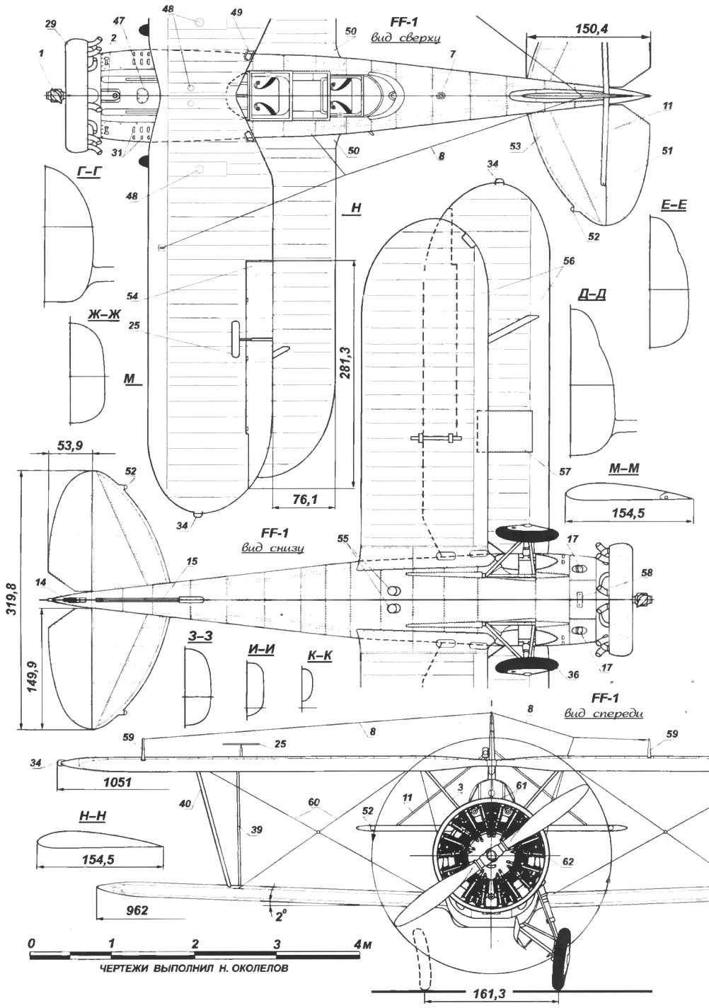
Flight characteristics of the fighter FF-1
Wingspan, mm…………………………..10 520
Length, mm………………………………………7460
Height, mm…………………………………….3350
Wing area, m2………………………..28,8
Empty weight, kg……………………………1395
Maximum takeoff weight, kg …..2111
Maximum speed, km/h…………..333
The rate of climb, m/s…………………..11,26
Range, ………………………….1178
Practical ceiling, m…………………6827
A. CHECHIN, N. Food reserve was
 Carrier-based fighter Grumman FF-1. Aircraft manufacturing firm Grumman Aircraft Engineering Corporation began work with the U.S. Navy in the late 1920-ies First, she collected the floats for seaplanes, and then began to build airplanes in their own projects, trying to use in their designs the most modern technology the First two seaplane G-1 and G-2, the proposed military was intended to perform reconnaissance tasks of the Machine all-metal construction was fitted with a retractable landing gear with a very original mechanism of their release, interested experts from the Bureau of Aeronautics of the Navy (BuAer): they rightly felt it necessary to use it on combat aircraft to reduce drag and increase speed flight, Especially needed in this chassis carrier-based fighter.
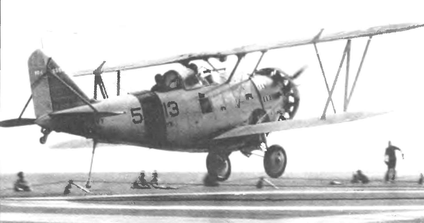
 CONTROL LINE AEROBATIC
  SPINNER — WIND