
 In the development of controlled anti-aircraft weapons of Germany during the Second world war, of course, surpassed all other countries. Work in this direction started there quite early and was based on a high level in the development of German science and technology. September 1, 1942, appeared the Memorandum of the inspector General, defenses of General von Axhelm, supported by Goering, who provided the following directions:
– the creation of cheap unguided rockets with engines for solid fuels for the barrage of fire in order to strengthen the existing air defense system on the following paths bombers;
– research and development of the larger guided missiles, solid and liquid fuel. The creation of missiles with visual tracking and radio control that could be established in the shortest possible time;
– research and development of guided missiles and proximity fuses.
It should be noted that this Memorandum was published and was distributed to various companies and organizations long before the massive bombing of German cities. Various companies and research organizations began to form small groups, departments, and bureaus, which worked to address these issues proactively, without an absolute funding from the state. Any coordination of work at this time was also lacking.
Enterprises with large tension work on the implementation of current military programs, so funding and supplying these groups and departments was carried out by a residual principle. The consequence of this was the slow pace of work and the lack of tangible success. Soon, however, a massive bombing became a reality, and design work has intensified dramatically.
By the spring of 1943, several projects ZURS was already well developed, and you could choose the most promising for further action. But a decision was delayed, and the Board of Dornberger made it only to the end of 1944, the Delay led to the fact that none of the samples ZURS did not have time to apply in a combat situation. In addition, they formed another bottleneck in the development of ZURS – by the summer of 1944, the research center in peenemünde was literally flooded with requests for testing prototypes of various systems and control samples themselves missiles. With these objectives the centre quickly and efficiently could not handle.
Purge a model rocket “Wasserfall” with the suspension
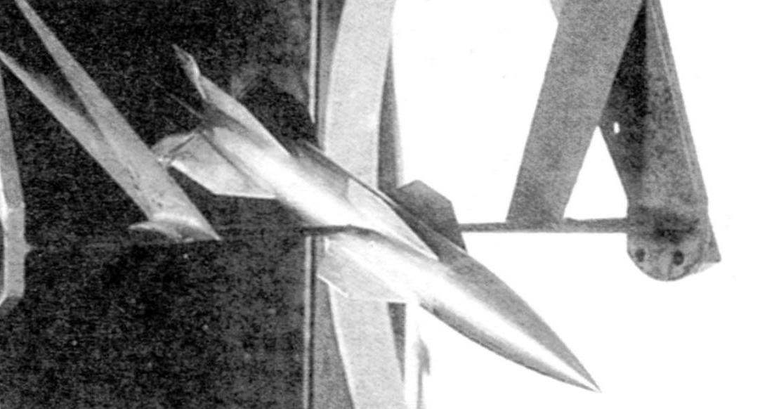
A model rocket “Wasserfall” in a wind tunnel
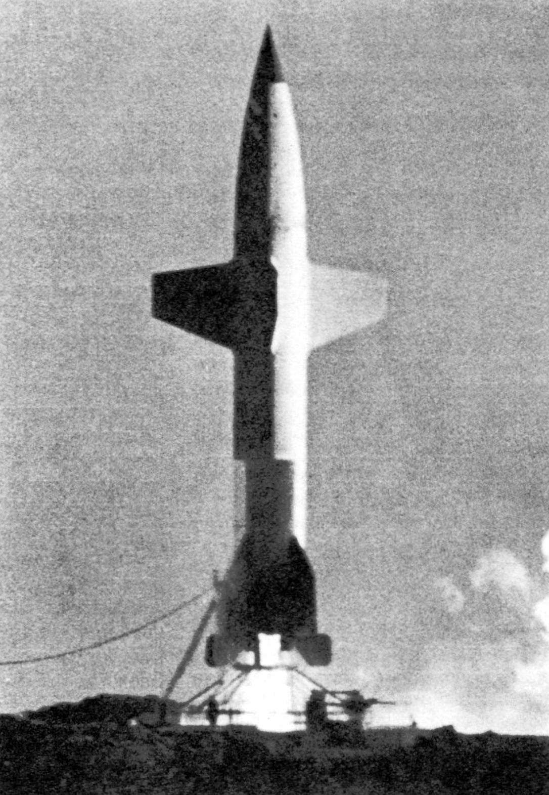
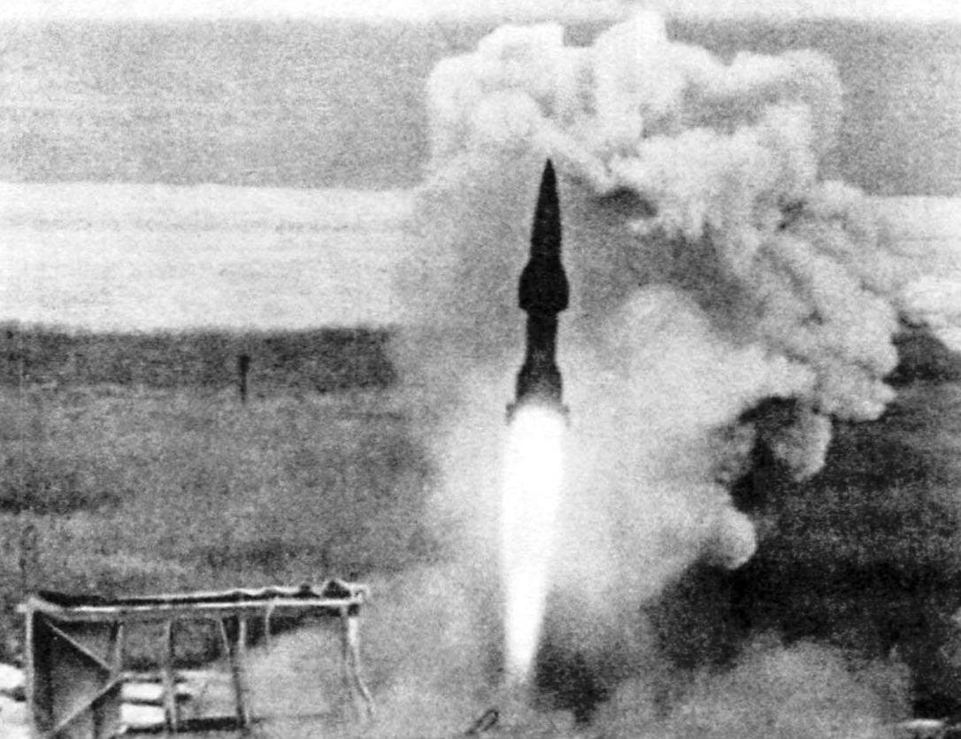
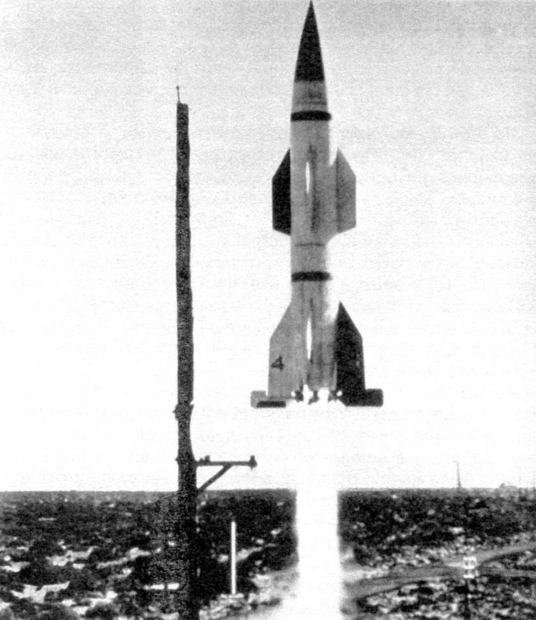
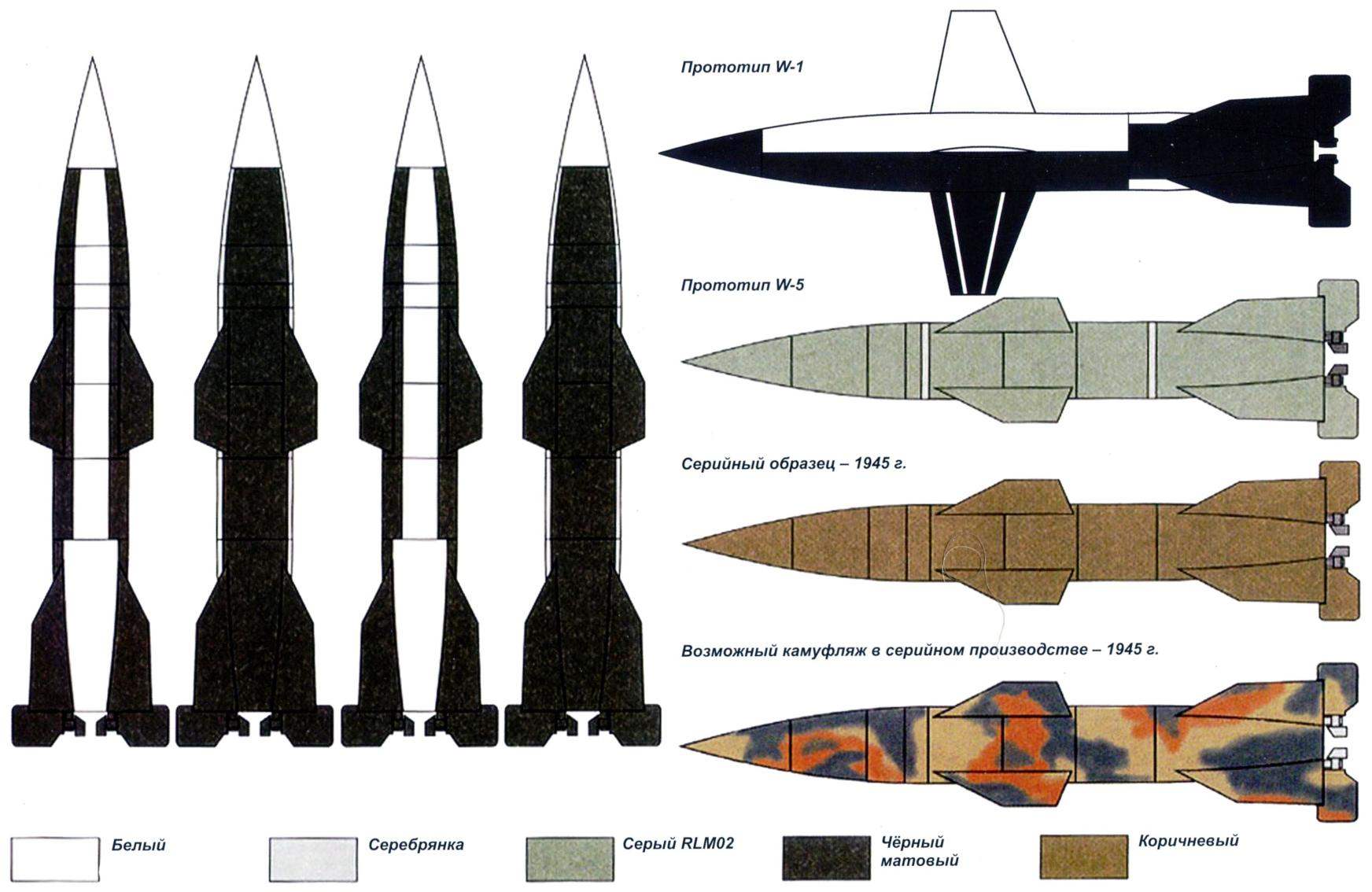
Start rocket “Wasserfall” W-1. The missile has a “checkerboard” coloring
Missiles “Wasserfall” (German – “waterfall”) – was one of the projects approved by the Board of Derenberger. At the root of the project was engineer Ludwig Roth, who worked in the Institute of ground forces in Peenemunde, who made the first estimations of the guided missile and believed that it will be able to adopt in 1945, about the time he was not far from the truth.
In response to the Memorandum from 01.09.1942, the plant of the Institute of ground forces sent their proposals under the name “missile” signed by the technical Director Wernher von Braun. The document contained a detailed calculation of three types of anti-aircraft missiles: 1 (length 6.4 m), two variants of 2 (length 6.1 m) and two With 3 (length of 10.06 m). Rocket 1, 2P (P-Pulver), and 3 were equipped with engine solid fuel, and 2F (F – Flüssig) – liquid fuel. Suggestions more than a year has lain in the vaults of the Ministry of aviation without movement.
In concept it was the most advanced system ZURS from all created at that time. In 1941 it was formed special design Bureau under the direction of V. von brown, who on 2 November 1942 the Ministry of aviation has concluded a special contract (and only in that time in this area of research) for the construction of missiles 2F, officially named Wasserfall W 1, so that the funding followed by the state. Simultaneously at the site of peenemünde-West was established “Test center of anti-aircraft guns” -in fact, the area in the stands to check not only weapons, but also missiles. There and based KB anti-aircraft missiles.
In fact, anti-aircraft missile “Wasserfall” was a side branch of the development of the rocket A-4, so it has traces of the many design solutions worked on V-2. For example, the fuselage of the “Wasserfall” is reduced by approximately twice the copy of the body of the rocket A-4, and as a construction material is also widely used steel and steel plate. Fuels were to be a pair: nitric acid plus alcohol, which was used in one prototype of the rocket A-4.
At the end of June 1943, by order of the Minister of armaments, peenemünde, visited the General Manager of chemical industry Professor, Dr. S. Crouch. After the inspection of new weapons and one of the prototypes of the rocket “Wasserfall”, d-R. Krauch wrote to the Minister A. SPIRA about a strategic error in the development of weapons. He offered to change priorities: to minimize the program of ballistic missiles A-4, focusing in favor of anti-aircraft rocket “Wasserfall”. Moreover, in July 1943, it was ready to test the first version of rocket engines for W 1. However, this appeal went unheeded. On the contrary, the program A-4 was rated the Highest importance (SS – SonderStufe), what’s worked so hard for von Braun. This decision allowed him to gradually pull professionals and funds in favor of the project A-4. Thus, administrative means almost managed to block the further development of missiles W 1. Neighbours from peenemünde-West was given the role of poor families and helpless supplicants. For comparison: on June 1, 1944 on anti-aircraft missiles worked 355 specialists, including 220 people on the program “Wasserfall” and 135 – on the program “Typhoon”, while on a program A-4 worked 2210 professionals.
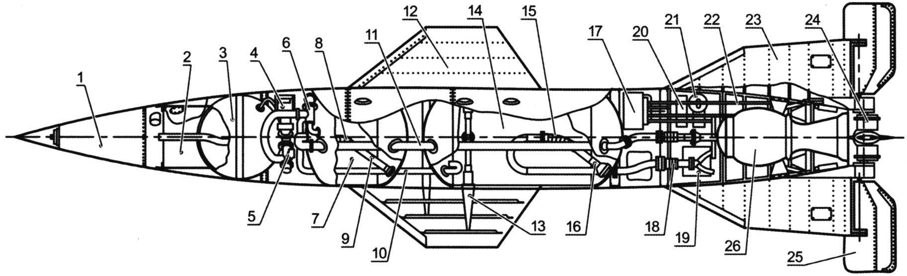
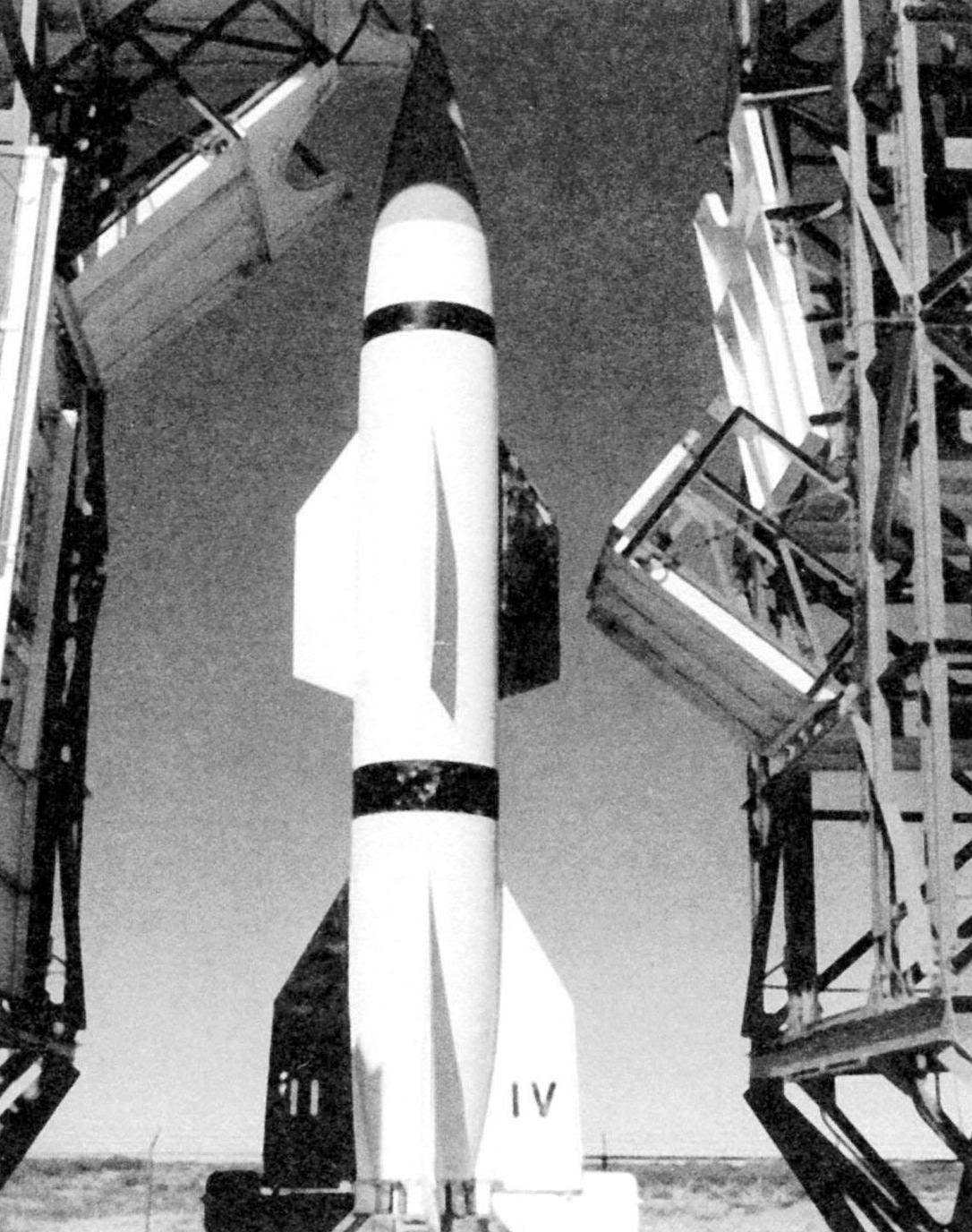
Layout ZURS “Wasserfall”:
1 – proximity Fuze; 2 – warhead; 3 – cylinder of compressed nitrogen; 4 – pyro valve; 5 – valve; 6 – pyro valve; 7 – fuel tank; 8 – flexible element; 9 – Zaborski of fuel; 10 – the pipeline pressurization of the oxidizer tank; 11 – fuel pipe; 12-wing; 13-spar; 14-oxidizer tank; 15 – flexible element; 16 – Zaborski oxidizer; 17 – control devices; 18 – expansion bellows; 19 radio; 20 – gyroscopes; 21 – servo-motor; 22 – thrust control of a gas wheel; 23 – the stabilizer; 24 – gas wheel; 25 – air wheel; 26 – chamber LPRE R IX
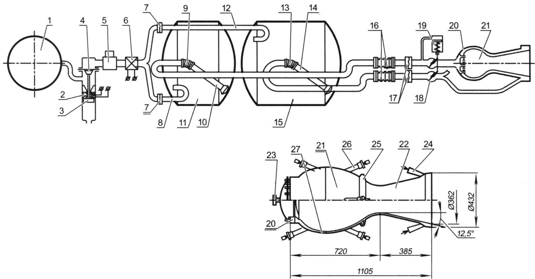
The scheme of the power plant ZURS “Wasserfall” with the engine R IX:
1 – a cylinder of compressed nitrogen; 2 – powder charge; 3 – piston; 4 – valve (high pressure membrane); 5 – pressure reducer nitrogen; 6 – pyro valve low-pressure; 7 – bursting discs; 8 – pipe pressurization tank of fuel; 9 – a flexible suspension of zaborska of fuel; 10 – Zaborski of fuel; 11 – fuel tank; 12 – pipe pressurization of the oxidizer tank; 13 – flexible suspension of zaborska oxidizer; 14 – Zaborski oxidant; 15 – oxidizer tank; 16 – bellows boxes; 17 – membrane on the lines of fuel and oxidizer; 18 – throttle valve; 19 – servopiston control throttle valves; 20 – nozzle head; 21 – combustion chamber; 22 – nozzle; 23 – throttle; 24 – feeding the oxidizer; 25 – expansion ring; 26 – mounting of engine; 27 – the outer shell of the combustion chamber
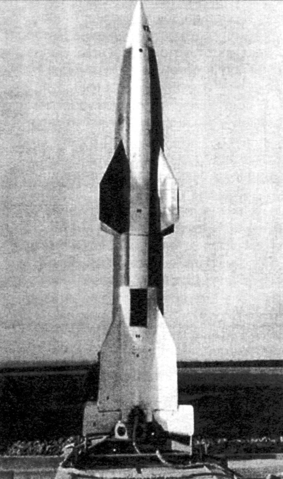
Prototypes of the rocket “Wasserfall” in the “checkerboard” coloring of the Photo: LuftArchiv.de
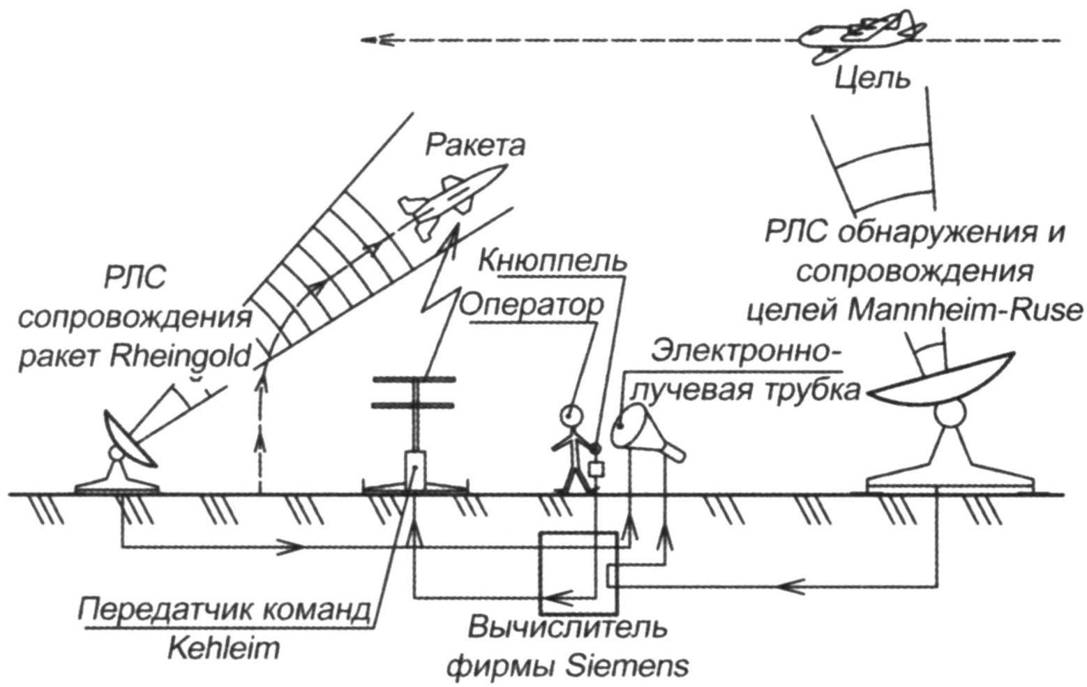
Scheme guidance ZURS “Wasserfall” with radar systems And Rheinland
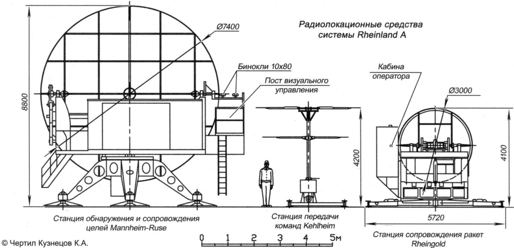
Radar means of Rheinland And
The operator controls the missile. The right – joystick left – cathode ray tube
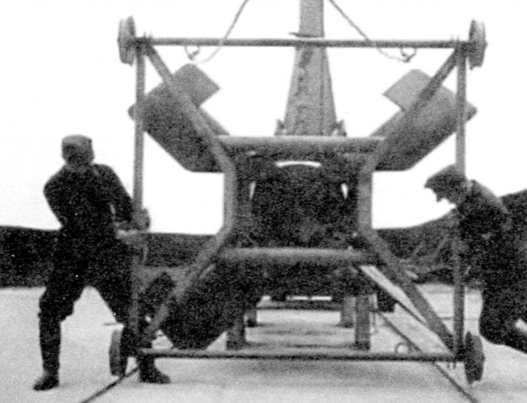
Erratic cart for missiles “Wasserfall” (newsreel scenes). At the start of the prototype truck somehow, not separated, and the rocket flew with her. After a climb of 100 – 200 meters, the rocket fell to his side and collapsed to the ground, 300 – 400 m from the start
However, work on the missile “Wasserfall” continued. The rocket was supposed to use against dense combat formations of enemy bombers, so that one blow to knock at least a couple of goals. However, studies have shown that despite the large warhead to achieve this will not be easy. Because the damaging effects of high-explosive charge is reduced to the third power of the distance. From one step to the use of liquid explosives, which will be discussed below. Therefore (according to requirements) rockets were used against individual targets, flying at high altitude with a speed of 720 km/h and maneuver with an overload to 2D. The firing range was assumed to be 25 km and reach heights of 15 km. To the other demands included term (several months) finding with fully fueled tanks to ensure operational use in any weather, regardless of ambient temperature, simple maintenance and simple discharge device for fuel.
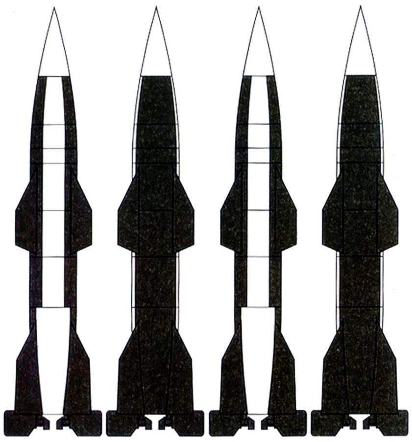
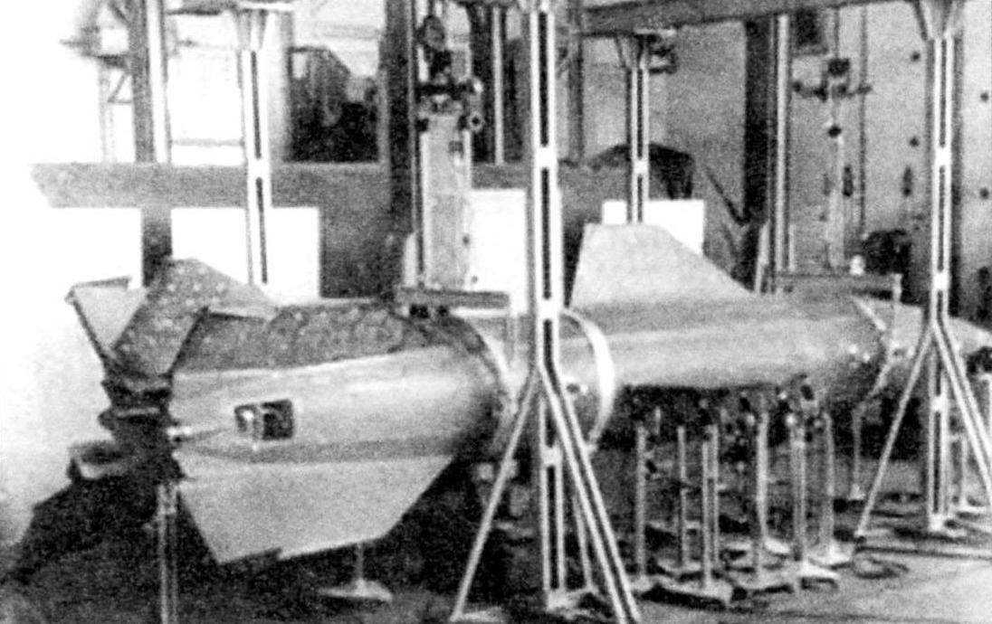
The first task of the designers was to determine the size and shape of the rocket body, which, when large-scale production must not restrict or reduce the existing capacity of the arms industry. The result suggested that full metal rocket, fusiform shape with a diameter of 0.88 m, with the extension of 8.46, provided in the rear large stabilizers.
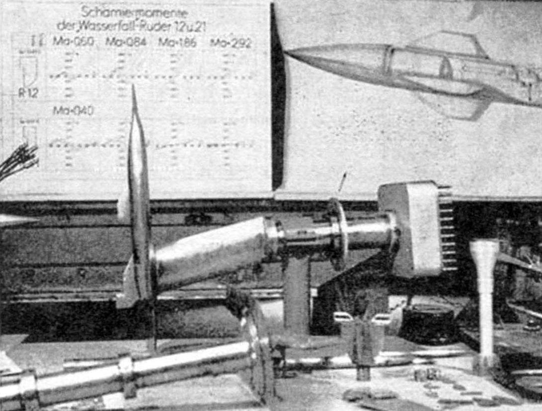
Aerodynamic venting the first model rockets (scale 1:25) was started in early 1943 in a supersonic pipe in peenemünde. After a night air RAID on this base, in August 1943 (at that time was not known yet important results of pipe dimensions) decided to stop aerodynamic venting and to relocate the pipe in southern Germany. In January 1944, in the town of Kochel, the pipe was again collected, but only in October put into operation. However, failed to reach the previous load on the pipe (in Peenemunde, she worked 500 hours a month, in Kochel – less than 200). Thus, was not timely received detailed and reliable scientific data from the field of aerodynamics of high speeds, which could be applied in the design of the “Wasserfall”, and why the designers left the only way is to rely on measurements and practical experience gained in the development A-4.
Time was running out, allied air raids intensified, forcing engineers to take missiles A-4 form of housing and stabilizer. Added only had gas and aerodynamic rudders, which could take from several tube experiments with rocket-4B with wings. In addition, during the purging has investigated different forms of aerodynamic control surfaces at subsonic and supersonic speeds, as well as the shape and position of the wings of different shapes.
The total length of the rocket was 7.8…of 7.93 m, maximum diameter – 885 mm, wingspan of stabilizers on the rudder -2510 mm. Rocket “Wasserfall” -1 nes a trapezoidal wings with a small sweep on the leading edge, as shown in the drawing. Then due to the large resistance at transonic speeds, they were replaced by smaller wings with sharp leading and trailing edges and a large sweep. First, the wings were attached with an offset of 45 degrees relative to the stabilizers. This was done to avoid shading of the wing stabilizers. Further research showed that the fears were unfounded, and the wings and stabilizers began to mount in the same plane.
Body, wing and stabilizer was a design with a working shell, representing a frame of prefabricated steel elements and cladding from steel sheets with thickness of 0.5…0.8 mm, welded to it by spot welding.
In the forward fuselage housed the equipment of the proximity Fuze (which had yet to develop) and a detonator triggered by radio command from earth.
In General, for anti-aircraft missiles were developed a whole range of proximity fuses:
“COCKATOO” – non-contact radio controlled fuses, using the Doppler effect, to operate in 15…25 metres from goal. It produced firm Donaulander GmbH for Hs 293 missiles. Due to the large structural complexity was produced only 3,000 pieces of the 25,000 ordered.
MARABOU – non-contact radio controlled fuses anti-aircraft missiles “Rheintochter”, “Wasserfall”, 117 Hs and aviation Hs 298 missiles, with a range of response up to 40 m. It was established on plants, Rheinmetall – Borsig and Siemens AG Halske, but not tested and remained in the stage of experimental work.
“PAPRITZ” – used infrared radiation of the target. Passed laboratory testing.
“VASSOURAS” active photovoltaic fuse, created especially for missiles “Wasserfall”. It consisted of a flashing light source and a photoelectric receiver responsive to the intensity of the reflected signal. Upon reaching its maximum warhead exploded. This principle was patented in Sweden in 1937, but the first workable pattern appeared after the war in 1946
One of these fuses was supposed to be set at ZURS “Wasserfall”, and yet decided to confine fuse controlled from the ground.
Followed compartment warhead weighing 250 kg. It contained 145 kilograms of explosives and 90 kg submunitions. In addition, there was an additional charge for the self-destruction of the missile if it misses. The problem of self-destruction was successfully solved – the pieces of the rocket had a weight less than 0.9 kg, and only chip the engine weighed 68 kg, work was Conducted on the use of liquid explosives. She was supposed to be sprayed into the air, and then undermined. The result is hoped to obtain a large area of destruction from the shock wave (a kind of forerunner of the modern space-detonating ammunition). But all this remained only on paper.
The prototype of the “Wasserfall” during horizontal tests. Rear fixed erratic truck
Takeoff rocket “Wasserfall”
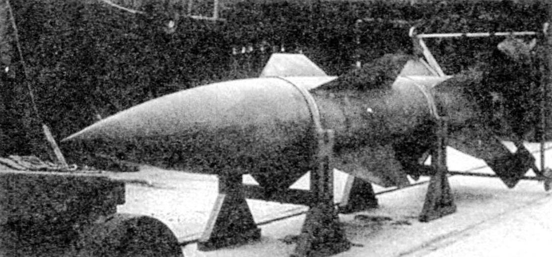
Loading missiles “Wasserfall” on a vessel for shipment to the United States
The first launch of the us version of the rocket Wasserfall – Hermes Al. Polygon white sand provin the ground (White Sand Proving Ground – WSPG), may 1, 1950
Below is the cylinder diameter 800 mm, made of two stamped hemispheres and is reinforced with a steel wire (like the cylinders have V-1). In the cylinder was compressed to 20 MPa (200 ATM.) nitrogen (according to other sources – air). It was followed by a tank of fuel “vital”. Even lower is the tank with the oxidant “salby”. The tanks were made of phosphated steel with a thickness of 6 mm.
The tank passed through the main spars of the wings. Then followed the instrument compartment with the control equipment and actuators, and finally, a special frame is attached to a liquid-propellant engine.
To the caudal compartment attaches four stabilizer with advanced air rudders and well-chosen aerodynamic compensation that reduces the required power servos and weight.
To control the projectile in the initial part of the trajectory until the speed was low and the effectiveness of aerodynamic control surfaces is not high, served as a gas rudders from graphite, which soon after the start of the reset. The starting weight of the rocket was 3530 lbs.
POWERPLANT MISSILES “WASSERFALL”
The scheme of the power plant shown in the drawing. As the missile was air defense, it is imposed on the power plant’s specific requirements. ZURS had a long time to be in charged condition and ready for immediate start. In this regard, liquid oxygen as oxidizer were not good, so I selected “salby” – 98…100%-nitric acid. Supply of acid was located in the rear tank and was 1500 lbs. of Fuel was called “vital” and was minimizebutton alcohol. Fuel “visol” + “salbei” was samovosproizvoditsja that allowed to refuse from the ignition system. Weight of fuel amounted to 345 to 360 kg.
Tanks of fuel and oxidant is carried out phosphatise steel of 6 mm thickness To protect against aggressive components of the fuel tanks from the inside covered with a special plastic. But despite the measures taken, due to corrosion of the fuel system retention time fueled missiles does not exceed a few hours.
Supply system components were pressure and was carried out by means of compressed nitrogen (see scheme). Nitrogen under a pressure of 20 MPa (200 ATM.) stored in a spherical container and the piping are transmitted to diaphragm valve high pressure. When submitting Electrosignal on this valve was the explosion of the squib, a special piston to the rod broke off the metal membrane and the nitrogen flow to the pressure reducer 5, where its pressure is decreased to 3.5 MPa (35 ATM.). Since then, the engine was ready to run. Almost simultaneously, the signal goes to the low pressure valve 6. It was pyro valve piston type, having two charges – one for opening, other for closing. The presence of a second team was necessary to stop the engine when you intercept the target at short range.
Further, the nitrogen burst membrane 7 and was received in tanks. The presence of membrane 7 and 17 was necessary to seal the tanks and prevent accidental mixing of the components.
After tank pressurization components have started to arrive in the pipelines. Fuel from the tanks climbed with the help of special zaborschikov 10 and 14, is suspended on a bellows joints 9 and 13, providing zaborschikov deviation after deviation of the masses of the liquids at the maneuvers of the missile. This design decision, in my opinion, is not certain.
Under nitrogen pressure, the fuel broke through membrane 17 (designed for 0.5 MPa, 5 bar) and started flowing into the engine. To ensure a smooth launch in the pipeline is located the throttle 18. When you start the engine they were kept half-opened. After the rupture of the membranes 17 fuel received into the cylinder of the band servo piston 19 which is under pressure of fuel moved slowly, opening the valve 18. This ensured smooth increase of the fuel supply and – quiet motor output mode. In the subsequent period of engine operation damper remains open. The engine – combustion chamber with nozzle and trigger system – had the designation R IX (R-Repetabs!e, IX – number assigned to peenemünde-OST).
Fuel was supplied to the head of the combustion chamber directly, and the oxidizer – after passing the cooling jacket of the engine. The fuel and oxidizer mixed, there snowspeeders and burned in the combustion chamber 21. There the pressure was 2.0 MPa (20 ATM.) the engine developed a thrust of the order of 78.4 kN (8000 kgf), for 40…45 seconds.
When developing the engine, the concentration of nitric acid reduced in order to reduce corrosion effects.
In the process of testing is known, at least three cases of explosions of the engine on the stand. In one case, during transport of the oxidant and during refueling in the rain. Acid adsorbed moisture from the atmosphere is increased its aggressive properties. The result was the sealing membrane, which led to the ingress of a certain amount of oxidizer into the combustion chamber. When you start the engine exploded. After that, the gas station began to carry out directly at the start, after checking the tightness of the system.
Preparing to launch one of the five launched missiles, the Hermes A-1 (Hermes Al). Polygon white sand provin the ground (WSPG), 1950 -1951.
Static testing of missiles R-101 (similar to the “Wasserfall”) at the Central research Institute of machine building of the USSR
The maximum theoretical engine operation time (45 seconds) he never achieved. The first of the tested missiles was the cause of the vortex occurring at craters of the fuel can be removed from the tanks. As a result, the pipeline prematurely fall nitrogen that reduced the engine operating time to 7 seconds. To mitigate the negative consequences of this phenomenon tanks were equipped with movable subordinate for suction of fuel. They are under the influence of acceleration was turned in space with a maximum depth of liquid. Mobility was provided with a metal (bellows) or rubber joints. The problem of corrosion protection in this case was very serious. None of the methods of selection of fuel developed by the engineer Mebusa, does not fully satisfy the conditions. Another problem was the loss of the velocity of the gases from the nozzle. According to the calculations, it was supposed to be 1870 m/s, but finally selected fuel rate amounted to only 1780 m/s, resulting in the need to increase the flow of ingredients for 2 kg/s.
LPRE of R IX with a thrust of 8000 kgf had a length of 1105 mm and a weight of 150 kg (with tanks, pipelines and valves – 800 kg). It consisted of a cast nozzle head, the combustion chamber volume of 78 liters, the nozzle with the throat diameter of 192 mm and an opening angle of 25 degrees.
The nozzle head of the first P IX were made from Nickel steel, and later developed a range of parts from light alloys. Fuel through it entered the combustion chamber through the nozzle 32. The oxidizer passed through a cooling tract, and then through the nozzles 128 are received in the combustion chamber.
CONTROL SYSTEM ZURS “WASSERFALL”
Initially it was assumed that the “Wasserfall” will be induced by the beam of the radar. In this case, the radar was supposed to track the target, and ZURS with Board control system had to be kept on the axis of the radar beam until the meeting with the target. The idea was certainly progressive, but such systems at the time were only at the initial stage of the research. Therefore, it was proposed that the guidance system using radio commands and two radars.
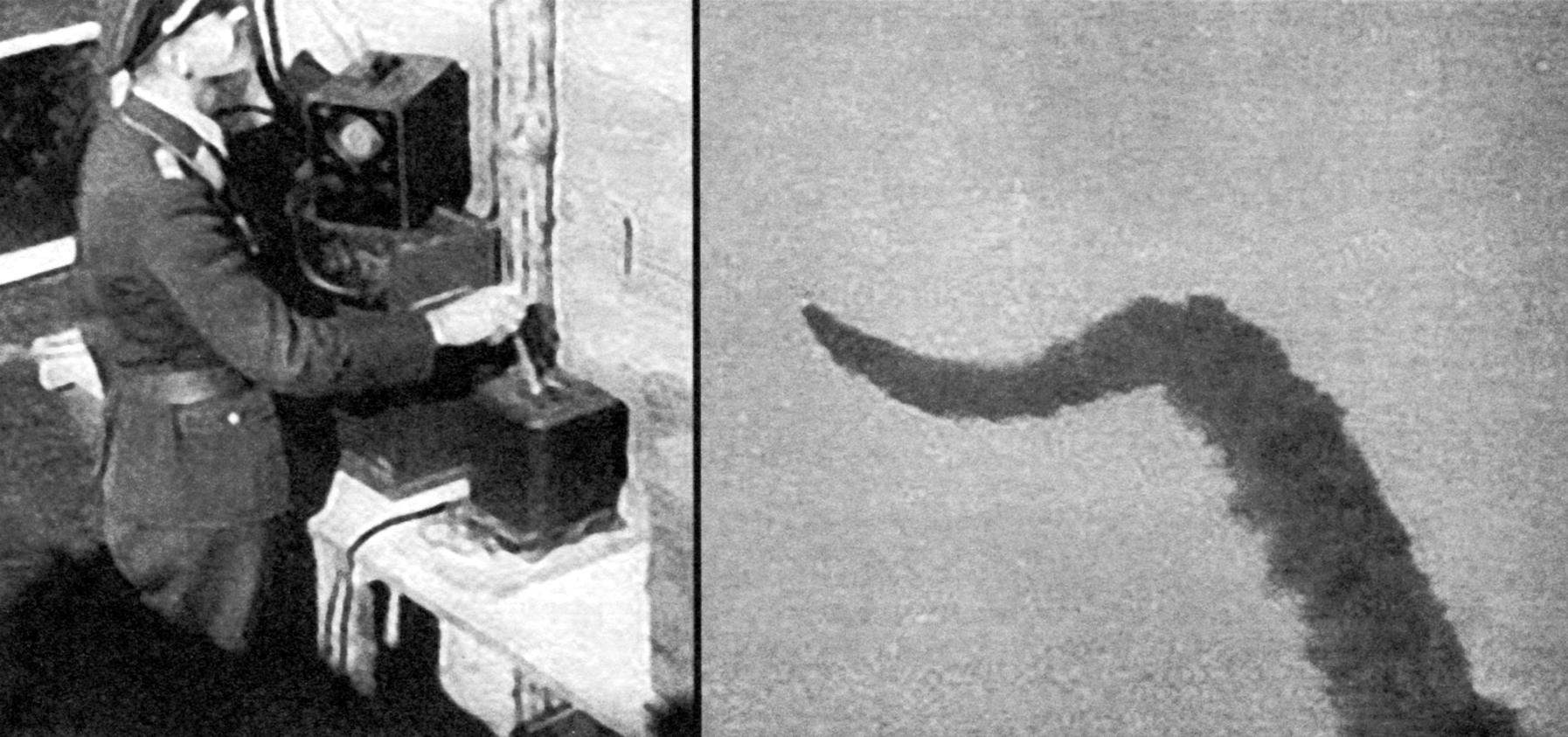
Under this scheme, one of the radar followed the target, a second tracked ZURS. Both mark (from target and missile) were displayed on one cathode ray tube. The operator using the handle on so-called “joystick” tried to combine on the screen of the mark from the target and ZURS. The signals from the “joystick” was received in the counting-critical device Siemens, where he developed the necessary commands which are from a transmitter via a radio channel transmitted to the missile. In good visibility the tracking of target and missile, the operator was carried out visually using binoculars. To facilitate the observation on the rocket you can install a special tracer.
Radar tracking of the target had a parabolic antenna with a diameter of 7.4 meters, and radar support of the launch of a parabolic antenna with a diameter of three meters. The system works in the UHF band. The transmitter of the teams had a circular polarized antenna operating in the VHF range. To simplify tracking the missile, it established a special radioattic.
On Board the rocket, the control signals are taken, desirability, amplified and transmitted to the servos of the type “Siemens K-2”. Stabilization of the rocket on the roll and vibration damping on the remaining axes were made onboard autopilot. Such a guidance system would provide all-weather capability of using complex “Wasserfall”.
The main part of the onboard equipment control was located in the tail section and closed by removable hatches. This simplified pre-launch service and precluded the use of high ladders (in contrast to the “V-2”, in which the instrument was housed in the nose of the rocket).
Executive bodies of the control system were four large rudder located on the stabilizer, and at the initial stage of the flight – four gas-graphite steering, is introduced into the jet engines. After dialing the required rate of gas rudders were dropped to reduce loss of traction. By the way, the discharged gas rudders were subsequently applied to some Soviet ZURS.
Development of guidance system using two radars was delayed, so the main bet had to do to use radio command system with the optical tracking target and missile. All-weather of course, was lost, however, such a system was more simple and reliable. Radio command control system were fulfilled by launching certain missiles A-4. For anti-aircraft missiles, German designers developed three systems of radio: “Burgund” (in three versions: FuG 203 “Kehl”; FuG 230 “Cehl” and FuG 230), “Strasburg” and “Franken” (in two versions: 512 FuG “Kogge” and FuG 530 “Brigg”), All of them had visual tracking of targets and missiles. It was assumed after the test to choose the best and use it in missiles. In the future, the radar system of the Rhineland And not suggested the abolition of the visual observation of the missile and the target.
It should also be said that ZURS “Wasserfall” was developed two infrared homing in the terminal phase of flight. These works have not reached the stage of preliminary studies.
THE PRODUCTION AND TESTING OF MISSILES “WASSERFALL”
The missile was presented on trials in February 1944, four months later than prescribed by the plan. According to one source, the first successful launch was performed on 28 February 1944 from the island Greifswalder. Thus a rocket at subsonic speeds reached a height of 7 km, then lost stability and crashed into the sea. According to others, the first successful launch was performed on March 8, 1945. The third prototype of the rocket has a top speed of 760 m/s and reached a height of 18 to 20 km exceeds the technical requirements set by the Commission of Dorenberg: speed – 600 m/s, the ceiling – 10 km, the horizontal distance of 32 km.
Before launch the missile “Wasserfall” was exported to erratic trolley to the starting position, where it refueled propellants. After the command to start the engine within 3…4 seconds left on mode and the rocket was off from the start. Stabilization of the rocket after takeoff the autopilot is provided with three gyroscopes, each of which worked on one of the main axes. After six seconds of flight were performed, the rotation of the missile on the target, until about 15…20 seconds of flight. It is not allowed to exceed the permissible angles of attack missiles – 15 degrees at subsonic speed, and 8 degree at a supersonic speed. Next, the missile onto the target, the commands calculated by the evaluator from Siemens or Kreisler.
Each of the four hydraulic or electric steering of cars worked on one gas and one aerodynamic the wheel. Graphite gas rudders, which the missile was controlled in the initial stage of the flight, after ten seconds of flight (at a speed of approximately 150 m/s) was separated using pyrotechnic cartridges. This discharge improves the performance of the rocket engine.
Graphite rudders almost become a serious problem in planning the production of missiles. In a letter dated 9.02 1944, Werner von Braun complained that: “…the Council of state refuses to put graphite rudders to W-5. Industry can not produce the required amount of graphite even for the A-4, due to lack of raw materials and production capacities”. The bulk of the graphite was in electrical engineering and in metallurgy. The planned volume of graphite for mass production of W-5 and A-4 was about 100 tonnes, which could result in a failure in the production of electrical products. Therefore, as a contingency, we studied the possibility of manufacturing gas rudders on the basis of ceramic materials.
Until February 1945, when the work at peenemünde was stopped, and the base began evacuation in Central Germany, was launched at least 44 missiles, mostly managed by the operator on the basis of visual guidance. Of them were recognized successful 12 starts. According to others, 25 rockets were fired, of them successful – 15. Mass production involves the production of 5000 missiles per month. Rocket divisions were supposed to cover all German cities with a population of over 100,000 people. Whatever it was, the missile was prepared for serial production by the end of 1945 could be adopted and applied in battle, but these plans went awry due to the end of the war.
Missile “Wasserfall” can be considered a missed chance of the German science and technology. Here he writes in his memoirs, former Minister of armaments of Germany albert Speer:
“I not only agreed with this decision Hitler (about the mass production of V-2. – K. K.) , and warmly supported him, and thereby made one of his most serious mistakes during the tenure as Minister of armaments. We ought to throw all forces and means for the production of missiles of a class “earth – air”. After all, if we focused talented professionals and technical staff, led by Vernier von Braun research center at Peenemunde, on completion of this, code-named “Wasserfall” anti-aircraft missiles, in 1942, could begin its serial production.
Homing (as in Speer. – ed.) missiles – eight meters long, the warhead weight about three hundred pounds, the ceiling is fifteen thousand meters could not leave virtually any bomber. Start it was possible to produce both day and night, regardless of clouds, frost and clouds. I’m still convinced that with these missiles and fighter jets in the spring of 1945, it is possible to protect our industrial facilities from air raids. In the autumn of 1944 finally became clear that our most expensive project V-2 was also the most meaningless.”
The history of the rocket “Wasserfall” not ended with the end of the war. Of defeated Germany, the Americans brought a rich scientific and technical trophies. By the way, they were in the Soviet zone of occupation.
In the United States after studying missiles “Wasserfall”, the firm General electric has created on its basis the experimental rocket Hermes A-1. As fuel and oxidant used liquid oxygen and alcohol. The control system was the original design. The geometric dimensions were the same as that of the “Wasserfall”, but the engine develops less thrust is of the order of 4500 kg. Hermes was an experimental design, and the question of its adoption was not raised. At that time the Americans had developed more advanced air defense missile “Nike Ajax.”
Soviet specialists were also examined and tested missile “Wasserfall”. It received the designation R-101. Here he writes in his memoirs, Vladimir Kazan:
“…Was first used high-boiling propellants: nitric acid and fuel oil-derived waxes “thin” (a kind of our kerosene). The fuel fed into the combustion chamber of the engine turbopump unit, and with the help of the air pressure accumulator (WADE); to have on Board the rocket, the air pressure of 350 ATM, the Germans manufactured by stamping and welding of the two halves of the steel ball with a diameter of about 800 mm, … wrapped in steel wire (note: the working gas is air and its pressure is higher than indicated in other sources – K. K.). Thus, it was assumed that the components of the fully fueled rocket with inflated to 350 ATM. pressure accumulators can be on the starting tables in constant combat readiness for a long time.
It has been said that neither a full set of drawings, nor parts and components from the missile to detect the failed (in peenemünde – K. K.). Therefore, all that is now evident, they had only to think. This was especially true of the system of missile control.
I should say that the first launches of rockets, as often happens, have been quite successful – the system of fuel supply and a rocket engine is well run, the engine has worked full impulse, working stabilization system (first gas rudders, then after they reset on aerodynamic). However, management system had certain shortcomings, and we were not able to achieve fully adequate reaction missiles at the position of the handle “joystick”, although at first there were a lot of optimists, especially those of the managers who assured us that “reasonable” behavior of the rocket.
It should be noted that the most significant (in comparison with the German missile) modernization it was done I. N. Sadovskii and A. M. Isaev (an upgraded missile received the designation R-102 – ed.). I. N. Sadovsky with his team managed to develop the design of the powder accumulator pressure (PAD), significantly lower weight, more convenient and safer than steel “bomb” with high pressure air from the Germans. At The Same Time A. M. Isaev created for the rocket a more powerful engine (9ТН) with the best relative indicators than N. L. Uman. Thus was obtained a significant gain in weight and thrust-weight ratio – just what the German rocket was not enough. And bench trials, and with the launch of the first modernized missiles it felt – it very quickly went from the start. Soon, however, other “systems analysts” slowly began to “eat” to gain an advantage, and it has gotten to the point that the last pascalcase missile barely looked up from the table, then due to the low speed of her ascent was demolished in the side and as a result, she fell 300 meters behind the start, never rising to the desired height. This launch was draw a line under the tests needed for our country’s missiles”.
From the above excerpt it is evident that the Union of the R-101 and R-102 and has not gone beyond the experimental samples, although it was in pilot production. These works are not left without attention of Western intelligence agencies and may have misled them. So, until the beginning of 1960-ies in a number of foreign sources have stated that the famous ring of air defense around Moscow armed with missiles “Wasserfall”.
MAIN TECHNICAL DATA OF THE MISSILE “WASSERFALL”
Length……………………………………………………………………7800 – 7930 mm
Maximum body diameter………………………………………..885 mm
The range of stabilizers…………………………………………………….2500 mm
Starting weight………………………………………………………………….3530 kg
The weight of the explosive charge…………………………………………………………….150 (100) kg
Weight of fuel……………………………………………………………..345 – 360 kg
The weight of the oxidizer………………………………………………………………… 1500 kg
Maximum speed……………………………………………………..760 m/s
The ceiling…………………………………………………………………………. 18 000 m
Horizontal range……………………………………..32,0 km
K. KUZNETSOV
Recommend to read
 THE PLANE, RESONABLEY THE MYTH OF THE INVINCIBILITY OF GERMANY
On the night of 8 August 1941 from the airfield Cahul, located on the island of Ezel (Saaremaa) in the Baltic sea, flew three groups of 15 bombers DB-ZT of the Baltic fleet. Aboard each... MAGNETIC WAND
In the repair of equipment there are times when a small detail falls into such a place, where to get it very difficult. And if a piece fell inside some mechanism? Then the continued...
