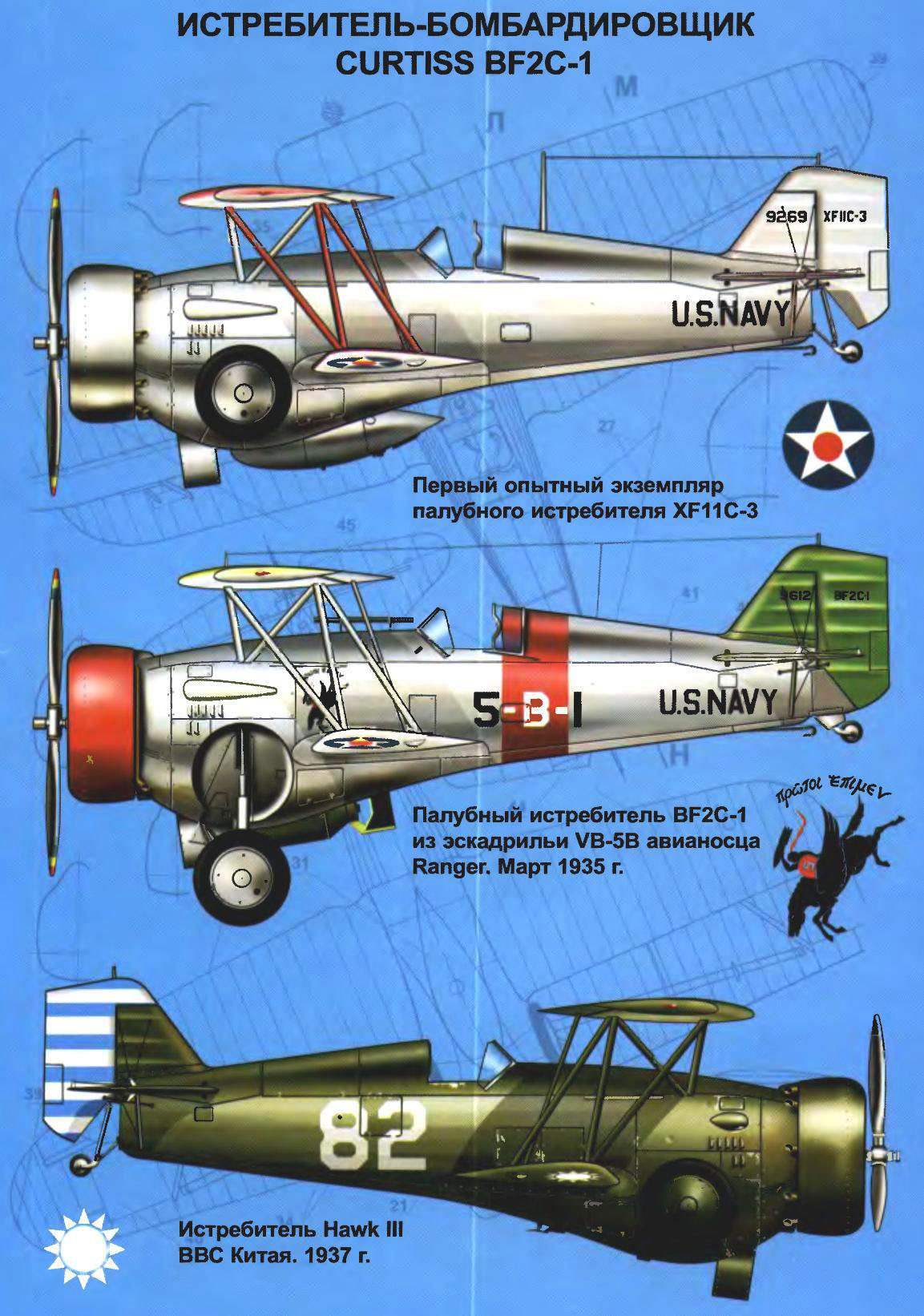
 Fighter-bomber CURTISS BF2C-1. The main suppliers of single carrier-based fighter for the U.S. Navy until December of 1932 was the company of Curtiss and Boeing. At first, when the Navy had only one aircraft carrier “Langley” and only two fighter squadrons of carrier-based aircraft, between these firms, there was little competition. Military aircraft bought in small quantities from the other, trying to equally support both an alternative source.
In 1927 the situation changed. In operation of the new included aircraft carriers “Saratoga” and “Lexington”. On each such ship could be based on up to 90 aircraft (for comparison, the capacity of the “Langley” was limited to just 34 aircraft). Now a number of squadrons of deck fighters has increased three times, and the minimum needs of the Navy in the fighter was estimated at 120— 150 aircraft. At the cost of one fighter of that time from 13 to 15 thousand dollars (Boeing F4B-1 was worth $15 000, a Curtiss P-6E — $13 000) contract amount could be over $ 2 million.
The fight for getting a lucrative contract turned Curtiss and Boeing in the ruthless competitors. The fight was won by the firm Boeing with its plane F4B-1, and erupted in 1929, the Great depression completed the complete defeat of a competitor, making Boeing an absolute monopoly. Three years after its “undivided sovereignty” she sold the fleet of more than 230 aircraft F4B various modifications.
All of a sudden in December 1932 on the aviation market was a little-known company Grumman, severely squeezing in this position of the company Boeing. “Culprit” of this event was created by the company carrier-based fighter FF-1 all-metal construction with retractable landing gear.
The following year, fortune finally smiled, and the Curtiss firm. The fleet drew attention to her promising fighter F11C Goshawk and ordered 29 of the modified aircraft of this type under the designation of the F11C-2. For the company, on the background of previous failures, it was a very important step forward. In an effort to gain a foothold in new positions and to expand the supply, the management firm Curtiss decided to use F11C retractable landing gear. The project of the new airplane gets the internal name of “Model 67”.
The military supported the innovation of the firm’s management and engineers have at their disposal the fifth production aircraft F11-2 with serial number 9269 for his trouble. System cleaning the main chassis has not been very original and almost completely repeated the scheme, patented by the firm Grumman. Gear wheels are drawn in a rounded niche on the sides of the fuselage by means of a chain transmission driven by handles in the cockpit For the arrangement of niches, and placement of the mechanism for cleaning the dimensions of the front part of the fuselage was increased. The weight of the aircraft structure increased by 104.4 kg, and to maintain the alignment of the top wing shifted slightly forward relative to its former position.
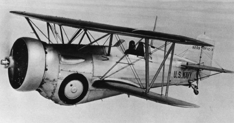
The first prototype of the fighter XF11C-3 in flight
Another difference of the new plane was the semi-enclosed cockpit. If necessary, the pilot could be covered from rain or snow small sliding canopy. This improvement proved to be quite useful, and in 1934, the same lamp was placed on the fighter-bomber version of the aircraft BFC-2.
Alteration of the machine was completed in the spring of 1933, and the Navy assigned the new aircraft the designation XF11C-3. The first flight of the upgraded aircraft was made in April 1933. May 27, 1933, the fighter was transferred for evaluation to the Navy. The report, compiled by marine pilots, was recorded the following characteristics: maximum takeoff weight of 2181 kg and the maximum flight speed of 348 km/h at an altitude of 2439 m.
The prototype was equipped with nine radial engine Wright R1820-80 air-cooled with a capacity of 700 HP and all-metal fixed pitch propeller. On production aircraft the firm planned to put the screw with adjustable step on the land that promised to improve flight characteristics. But even without this XF11C-3 had surpassed the speed of its predecessor F11F-2 of 22.5 km/h.
During flight tests on the ailerons and the rudder put operated trimmers. 26 February 1934 the Navy ordered a small series of 27 aircraft F11-3, they all had to go into service the new aircraft carrier “Ranger”. However, his fighter squadron planned to equip the BOEING F4B-4, which apparatus is of the firm Curtiss took the role of fighter-bombers and changed their designation to BF2C-1.
The design of the F11C-3 had to make changes in accordance with his new assignment. In the recess between the fairings of the mechanisms of the landing gear secured to the suspension unit 227-kg bomb or a fuel tank capacity of 189 L. in addition, wooden power set of the wing was replaced with a lighter metal.
During flight tests the prototype XFB2C-1 crashed on takeoff due to engine failure. This occurred on 24 September 1934 at the airfield airbase Hamptons road, Virginia. The military didn’t pay the incident any attention, because before the prototype flew without comment over 254 hours. The amount and timing of the order remained unchanged.
The first production aircraft was transferred to the Navy on 7 October 1934. It was the engine R1820-04 700 horsepower at a height of 2438 m. production vehicles sold to the military for $18 000 per copy, with a third of this amount accounted for of the engine.
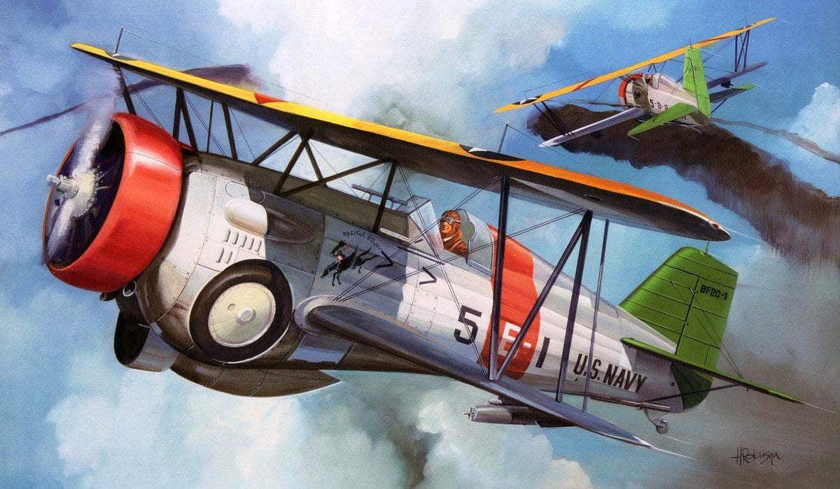
The acquisition of carrier-based squadron VB-5B aircraft carrier “Ranger” of the new aircraft began in November 1934. Sailors used the BF2C-1 and as a fighter, and as a dive bomber. In fighter version takeoff weight does not exceed 2068 kg and a maximum burst speed of a sample was 362 km/h. the mass of the aircraft in the bomber version increased by 241 kg, the maximum flight speed dropped to 346 km/h.
Drill the pilots were extremely unhappy with the new plane. In flight at cruising speed the wings began to vibrate dangerously, turning FB2C-1 in the flying “hammer”. The culprit of this extremely unpleasant phenomenon revealed only after a specially arranged test stand. Before the aircraft was mounted in-line engine water-cooling V1570 and Abduvali design air flow from the propeller. Own engine fighter were not included, and dangerous oscillations in this case did not arise.
Engineers came to the conclusion that the blame for the coincidence of the natural frequencies of the engine and the wing. Problem tried to resolve by consolidating the cargo at the wing tips, changing the frequency of a harmonic of their oscillation, but flight tests nearly led to disaster. Overloaded racks and braces the box of wings began to break down.
The firm offered the Navy another way to replace the wings of metal structures of all aircraft on the wood of the export variant of the F11C-3, which have similar trends to the fluctuations was observed. The cost of such operations exceeded all reasonable limits, and the big need for it was gone. The Navy has ordered a large shipment of fighter F3F the Grumman company, and BF2C-1 were written off in the coastal part. The last aircraft removed from service carrier squadron VB-5B in February 1935.
Before the advent of F3F unit temporarily manned aircraft Boeing F4B-4. Not to mention about one important disadvantage BF2C — vibration of the tail in the presence of the load on the Central pylon. This disadvantage is eliminated quickly and efficiently securing the load ring in front of the stabilizer air flow. Seen from the side it resembled a pull-out cooler.
Failure BF2C-1 resulted in serious consequences for the firm Curtiss. In the Maritime Ministry raised the issue of the termination of further cooperation with the company in the creation of a carrier-based fighter in connection with her inability to design a certified aircraft. In response, the firm has tried to adapt BF2C-1 for training purposes, but this initiative was rejected. In January 1937, the flights on the BF2C-1 was banned. The remaining ekspluatacii 19 cars gathered at the base in San Diego, where they removed all the valuable equipment and the remains of the aircraft were loaded onto a barge and dumped at sea. BF2C served on the aircraft carrier just four months, putting a record in the nomination “the most short-term service in carrier-based aircraft of the United States”.
The fate of the “land” version of the fighter F11C-3, known under the designation Hawk III has developed more successfully. From deck variant, it featured a lack of brake hook, three-bladed propeller and wooden wing power set (the metal was used only in the frame of the ailerons). The base power plant was the engine WRIGHT SR-1820F-53 of F11C-2.
All aircraft sold abroad. In April 1935, one F11C-3 sold in Turkey. In August, we began to supply 24 aircraft to Thailand (Siam). Next year ten fighters bought by Argentina.

Fighter-bomber BF2C-1:
1 — steel two-bladed propeller with a constant pitch Hamilton standard; 2 — hood; 3 — fairing machine gun; 4— control rod Aileron; 5 — canopy cockpit; 6 — sliding part of the canopy; 7 — antenna radios; 8 — keel; 9 — rudder; 10 — tail wheel; 11 — rack tail wheel; 12 — a brake hook; 13 — step; 14 — operational sunroof; 15 — wheel main landing gear in the retracted position; 16 — brace fin and stabilizer; 17 — removable cover emergency equipment; 18 — sliding part of the canopy in the open position; 19 — exhaust pipes; 20 — a three-bladed propeller Hamilton standard; 21 —ring stabilizer; 22 — hatch access to the station; 23 — hatch access to rudder mechanism of the stabilizer; 24 — slot release of the cooling air; 25 — fuselage struts of the upper wing; 26 — telescopic sight; 27 — cable the radio antenna; 28 — the stabilizer in a negative angle; 29 — trimmer of the rudder; 30— brace stabilizer; 31 — external fuel tank; 32 — struts-the struts of the wing; 33 — front of the main wing; 34 — braces wing; 35 — lifting nodes; 36 — machine guns Colt-Browning; 37 — wheel main landing gear in the released position; 38 — bombs caliber 45,3 kg; 39 — ANO; 40 — Aileron; 41 — stabilizer; 42 — the hinge of the Elevator; 43 — the steering wheel height; 44 — trimmer of the Elevator; 45 — rocking the rudder; 46 — built-in rubberized bag
The greatest number of Hawk III has purchased China — there, since 1936, was delivered of 102 aircraft. Almost all Chinese Hawk III has arrived in a disassembled state and assembled by local workers in aviamaster.
On 14 August 1937 the Chinese Hawk III engaged in battle with Japanese planes. Chinese pilots fought bravely against superior 13 times enemy forces and successfully led interceptions of the bombers. For example, in the first day of the war they managed to shoot down three bombers MITSUBISHI Tip 96 (G3M2). However, please note that these bombers flew without fighter cover, and their tanks were nepaterizovanny.
But at a meeting in the air with Japanese fighters the chances of the HAWK III was small, and not only because of the numerical superiority of the Japanese. Their main fighter — NAKAJIMA Tip 95 (A4N1) was nearly one ton lighter, and the engine was 30 HP more powerful than the American motor WRIGHT. Just a couple of months, the Japanese won air superiority, and after the fighter-monoplanes А5М destroyed almost all Chinese aircraft.
The government of Chiang Kai-shek appealed for aid to the Soviet Union In October 1937 in China began to receive the first Soviet fighters: I-16, I-15 and I-153. All the remaining HAWK III fighters and other older planes American, Italian and French production moved into the category of training machines. They occasionally continued to take part in the fighting, and by 1941 had been destroyed. Total built 139 fighters F11C-3.
Design description
The plane was a single-seat carrier-based fighter-bomber of mixed construction with retractable landing gear. The fuselage is functionally divided into three parts: the front (bow), medium (Central) and tail. Truss fuselage structure typical of all the previous fighters of the firm. The farm was a welded construction of steel pipes. For forming the longitudinal Central and rear fuselage were used dural l-shaped stringers.
In the front part of the fuselage on Motorama the engine was installed with the devices and assemblies fuel and oil systems. The engine has closed dural quick release hood type NACA. Between the cockpit and the engine are the oil tank, two fuel tanks, a niche cleaning the main landing gear and machine guns with ammunition boxes.
The mechanism of cleaning and landing gear were fixed on the power frame. From below in the mounting area of the chassis, the fuselage had a Central recess with holders outboard fuel tank or 227-kg bombs. The forward fuselage was closed with a quick-detachable duralumin panels, providing convenient access to machine guns, oil and fuel tanks, the mechanism to retract the main landing gear.
The cockpit is semi-enclosed type located in the Central part of the fuselage. Front pilot covered visor consisting of three rectangular Plexiglas panels. Before the visor on two uprights were fixed telescopic sight. Side of the pilot’s head was covered by a lantern, dvigausciesya if necessary ago. The pilot seat, height adjustable, consisted of two profiled aluminum parts. Headrest seats have soft, covered with leather cushion. Reservation was missing.
Instrumentation housed on the Central fascia panels and on the Central bottom panel, a so-called “beard”. Part of controls and equipment (e.g. lever engine control, wheel rudder stabilizer) were placed on the sides of the cab. Trim middle part of the fuselage fabric.
Immediately behind the cockpit, started the aft fuselage. The upper part formed a fairing — fairing headrest of the pilot, closed dural panels. Under the removable panel of the fairing was laid rescue equipment — inflatable rubber raft, a supply of food and drinking water, and flares. At the bottom of the outside compartment installed in the power station; for its service in the left side of the fuselage was provided with rectangular quick-release hatch.
To the rear of the fuselage is attached to the stabilizer and fin with rudders and height, and front tail spike wheels.
The wing of the plane made by the scheme biplane, and has all-metal construction. The upper wing consists of a center section and consoles. Power set of the wing is formed by two spars and set of ribs. Dural spars, box-type. The ribs are also made of metal. Wing tip in special sockets fit the ballonets bags made of rubberized fabric to ensure the buoyancy of the aircraft when making a forced landing on the water. Filling the ballonets with compressed air produced by the pilot with the valve located to the right of his chair. In the center section of the upper wing at the trailing edge was cut to improve visibility of the upper hemisphere.
The lower wing consisted of the left and right consoles and in construction differed little from the top. Each console lower wing is positioned in the two holders for a 45-kg bombs. The upper and lower wings were connected by two N-shaped struts. The same under-braids-struts, the upper wing attached to the fuselage. On the right wing strut was fixed to the receiver air pressure (LDPE) pointer speed flight.
Brace-wing — steel cable, doubled. The ailerons are located only on the upper wing. Control ailerons hard, through the rod pushrods going to the ailerons from the lower wing. The wing skin fabric. The ailerons of the wing had a duralumin skin.
Tailplane composite construction. Power set, consisting of spars and ribs, is made of aluminium alloy. Covering all surfaces of the tail plain. The rudder horn is made with aerodynamic compensation. Trimmers were installed on both the rudder and the elevators. The design of the stabilizer was provided the opportunity to change angle installation screw mechanism. To ensure the necessary rigidity of the stabilizer and fin are contracts between a cable braces. Control the control surfaces of the cable.
The power plant of the aircraft includes desyatitsentovoy the engine of air cooling WRIGHT R-1820-04 CYCLONE. On most aircraft the exhaust manifold is missing. Each cylinder is equipped with an individual exhaust pipe, diverting the exhaust from the fuselage in a free stream. Engine management is done by the control lever engine (ORE), mounted on the left side of the cockpit. Manned aircraft two-blade metal variable-pitch propellers Hamilton STANDARD company.
Fuel contained in two fuselage nepaterizovanny fuel tanks with a total capacity of 418 liters. Front lower 209-liter was placed immediately behind the power frame and niches of cleaning the main landing gear struts. Rear upper the same capacity (209 liters) was located just above the front. Among themselves they were not connected and had separate filler. Development of fuel is carried out alternately from the transferee and rear tanks. Placing them near the center of gravity does not violate the alignment of the aircraft and did not affect its handling. At the bottom of the fuselage it was possible to install additional overhead 189-litre tank. For engine oil system tank capacity 34 l is mounted directly behind the engine, before fuel tanks.
The chassis is retractable, with the tail spike wheel. Stand the main chassis of the pyramidal type with oil-air shock absorbers. The system of harvesting and the landing gear is typical of the first American aircraft with retractable landing gear the first half of the thirties. Cleaning was carried out by retraction of the landing gear inside the fuselage by means of a chain transmission driven by a knob on the left side of the cockpit. When the wheels are placed in special niches on the side panels of the fuselage. Stands were fixed on the strengthened power of the frames, simultaneously performing as a fire wall. Main wheels were equipped with air drum brakes. Stand freely oriented tail wheel had a rubber cushioning.
The armament of the aircraft consisted of bomber and missile. The latter was represented by two synchronized fuselage 7.62-mm machine guns COLT-BROWNING with ammunition at 600 rounds per gun. Four bomb racks were placed small bombs caliber or 45,3 52,6 kg. In the Central ventral node of the suspension can be suspended for one 227-kg bomb.
Flight characteristics of the aircraft F11C-3
Wingspan, mm…………………….9600
Length, mm……………………………….. 7000
Height, mm………………………………3100
Wing area, m2……………………24,3
Empty weight, kg…………………… 1511,4
Takeoff weight, kg…………………2309,0
Maximum speed, km/h……..362
Rise time
at a height of 1524 m, min………………….4
Practical ceiling, m………..8229,6
Flight range, km……………. 1282,4
N. Food reserve was, A. CHECHIN
Recommend to read
 HONDA S2000
Scale model 1:18. Honda S2000 — the car rear-wheel drive front-engined and rear wheel drive Roadster with equal weight distribution on front and rear axle, manufactured by Honda.... LISTEN TO THE HEART
On the radar heard many. The transmitter sends powerful electromagnetic wave in the direction of a moving object (airplane, ship). Upon reaching it, the wave is reflected and received by...
