TILLER – MANUAL

TILLER - HANDCultivation, furrows, weeding between the rows, earthing up of the plants… For these and other works is a lot of mechanisms and machines. Often quite complex, scarce and expensive. Where plot sizes are small and the soil light, many prefer to settle for a commercially available hand-cultivator-Hiller ROC-35A. And here are a couple or alone, characteristic for the latter case, the method “one step forward, half step back”: moving a considerable shock, but with a small (5-10 cm) back.

Appeared tempting (and, quite feasible by forces of students of syut) idea: to provide whether the cultivator is a simple internal combustion engine? For example, from the moped. Power transmission? It was decided to do a two-step, chain — PR-a 12.7. And as the stars adjust not scarce bike (with the number of eubie equal 41) and the D6 engine (g-10) — see kinematic scheme.

The work we began with the alteration of the frame of the mouldboard. Here was cut the plug of fastening of a wheel, and in its place by means of electric welding firmly attached a new, somewhat elongated. The front end of this plug is additionally reinforced welded pipe, which serves as a supporting element for the engine and intermediate shaft. As the Hiller we have become self-propelled, have a regular forged wheel has also been reinforced preveiw on the hub and rim three-spoke. And cut it from 2 mm sheet steel. The wheel was supplied by twenty-fatty cleats of the 60-mm cuts steel area of 20×20 mm on the left (in the direction of Hiller) side on the wheel hub welded a bike sprocket with 41 tooth.
 
Powerplant (engine D-6) equipped with forced cooling. For this kryske clutch of the engine is wasted through hole 29 mm coaxial socket webmastery crankshaft (through the hole will be hub-hub and bolt-on axle for the impeller). And the impeller are made of duralumin sheet thickness 0.5—1.0 mm.
 
The layout of the cultivator-Hiller (casing removed)
 
The layout of the cultivator-Hiller (casing removed):
1 — wheel with grousers (from hand cultivator OCD-35 A) 2 — Zvezdochka G4=41,3 — spoke three-beam welded, 4 — frame, 5 — tube exhaust with muffler, 6 — D-6 engine modified with the fan cooling system, 7 — tank 9 — asterisk G2=10 of the intermediate shaft 11 and the tube frame reinforcement, 12 — arm with the handles the clutch and throttle of the carburettor, 13 — adjustment mechanism and mounting arms, 14 — device mounts work item 15 — paw cultivator-Hiller (3 PCs.), 16 — wheel with grousers.


Kinematics of motomania
 
Kinematics of metopomancy:
1 – fan air-cooled self-made, 2 engine D-6 modified 3 — wheel (C)CU-0.35 A), with twenty lugs and welded on a sprocket, 4 — wheel axle, 5 — bearing unit (off the bike), 6 — intermediate shaft with a drive pulley and two asterisks two-stage chain transmission PR-a 12.7.


Frame and the location of the main nodes on it (look on the right hand side of tiller)
Frame and the location of the main nodes on it (look on the right hand side of tiller):
1 — working bodies of the cultivator, 2 — not subject to alteration part of the frame)CU-0.35 A with adjustment mechanisms and attachment of the handles and of the working bodies, 3 — arm (with handles clutch control and the throttle valve of the carburetor), 4 — pipe frame reinforcement, 5 — intermediate shaft with a drive pulley and two asterisks two-stage chain transmission Г1Р-12,7,6 — fuel tank on a tubular /-shaped rack, 7 — modified D-6 engine mounted with a fan-cooling system, 8 — exhaust pipe with silencer 9 — tubular U-shaped frame part, 10 — wheel with grousers and weld sprocket Z4= 41.


Frame to (a) n after (b) alteration
 
Frame to (a) n after (b) alterations:
1 — not subject to alteration part of the frame)CU-0.35 A with adjustment mechanisms and attachment of the handles and of the working bodies, 2 — tubular U-shaped frame part, 3 — tube amplification.


Technical data of the tiller
 
 
Part of the engine to set it on a fan
 
Part of the engine to set it on the fan:
1 — nut shaped, 2 — bottom cover casing (St. 3), 3 — hub-spigot (Art. 45), 4 — bolt-axle (CT. 45), 5 — fan impeller (sheet aluminum), 6 — upper part of the fan shroud (tin or iron roof), 7 — M4 screw (4 PCs), 8 — cover-clutch, 9 — M5 screw securing the clutch cover. 10 — a leading gear. 11 — right half of the crankcase.


Intermediate shaft Assembly
 
Intermediate shaft Assembly:
1 — nut shaped, 2 — pulley (drive washing machines “Riga”), 3 — Bush (bearing Assembly from the pedal bike), 4 — base plate (5-mm sheet St. 3), 5 — sprocket Z2=41, 6 — asterisk Zз=10, 7 — shaft (axle).


Paw cultivator
 
Paw cultivator.
 
The workpiece, of course, mark; drilled mounting holes. Then madrobot chisel on the lines B (see Fig.), cut with scissors on the line and the resulting blades are bent on the line A. To the crankshaft so the impeller is attached with a hub-sleeve, shaped nuts and special bolts M8. However, it is necessary to perform… partial bulkhead of the engine itself. At a pretty simple technique.
 
First, it is necessary to move the cylinder head to be rotated so that the vertical fins were mounted perpendicular to the lid of the clutch. Then using a regular puller should be separated from the axle of the crankshaft drive gear. The latter is clamped in a Vice (after having protected her from “crushing” plates of aluminum or copper) and transferred to the fan.
 
The impeller is tightly screwed onto M4 screws to the hub-the hub with the obligatory raskladyvanii fasteners from the back side. The M20 thread is screwed a shaped nut (the slots to the impeller), thus preparing a node for a connection with the pinion gear.
Sheet metal-made bottom cover fan shroud and installing it on the cover clutch tan that both parts are maximally aligned, connect them by screw MB. Through the holes of the casing cover Cernat in the lid of the clutch centers additional mounting holes, then remove both parts from the engine, drilled the missing holes in them and cut thread M5. Installing the clutch cover in place, screw it to the fan cover.
 
Now pass to the trunnion of the crankshaft. Putting on her gear Assembly with the impeller, the hub-shaped sleeve and a nut rigidly fixed it all together with a special bolt M8 placing it on a spring washer (in the drawing the latter is not shown) and bursting tightly shaped nut svincova the latter with the threaded section of the hub-sleeve.
 
The upper part of the fan shroud is cut from a sheet of tinplate, or roofing iron with a thickness of 0.3—0.5 mm. Bending the workpiece along the thin lines and by folding it inside the “reeds”, probailout seams and install the cover on the engine. As far as the holes in the cover under the candle and the mounting holes in the bottom cover, then obey them “in place”, during installation.
 
The intermediate shaft is assembled on the basis of the pedal from the bike. And the shaft (axis) it is better to re-carve of Steel 45. This in order to make it easier to spread on the one side of the timing pulley and on the other welded together stars vol. 2 and 7.b. But you can manage to do the latter and using the former (foot) shaft.
 
All the tubular elements of the power structure of the tiller, including removable arm made of segments of vedovato-wired pipe 0 ‘/2″. When bending the internal cavity is recommended to fill (to avoid cracks and breakage) sand. In winter you can do without sand, replacing it with water with subsequent freezing (into ice)— high quality and smoothness of the pipe bend guaranteed.
 
Fuel to the engine is supplied by gravity from the petrol tank (on a moped “Riga”) mounted on two tubular uprights welded to the hub of intermediate shaft.
 
The operation of the clutch and the throttle of the carburetor taken from the bike, cables from the scooter. To achieve more convenience (in use) behind the handle grip to the handrail drilled through hole 0 4 mm, which are inserted in the clamp fixing lever in the released position (when the engine is started). And implementation of removable handles makes it easy to place the tiller in the trunk of a car or in a sidecar.
 
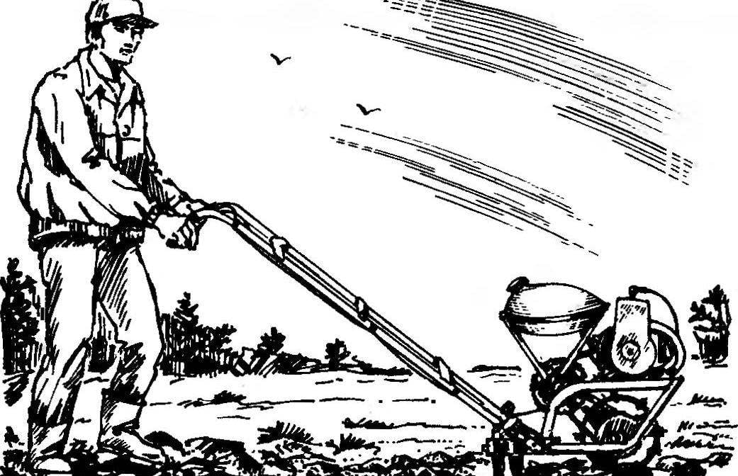
In field trials (cultivation of potatoes) our Moto pomoshnik have shown enviable efficiency: the processing of fifteen acres took only one hour.
 
V. FEDOTOV, head twist syut, Bashkortostan

Recommend to read

  • BIKE LOCKBIKE LOCK
    A small segment of a steel cable clad in a tubular plastic case, with their ends included in a metal cylinder smaller than a hockey puck. This is a bike lock designed to prevent...
  • AND SCREWAND SCREW
    Wooden parts are often connected by screws. However, this connection is not always acceptable if you are dealing with blanks, for example made of chipboard, which in this case pipetted...