
 Long-range bomber Tu-16. Large-scale development of high-speed jet bombers, long-range flight, which began in the USA after the Second world war, could not remain unnoticed in the Soviet Union. A year after the publication of American requirements for such aircraft (in late 1946) to the design Bureau of A. N. Tupolev, Ilyushin and Sukhoi began the design of machines with the same parameters.
On most of their aircraft used turbojet engines with a centrifugal compressor RD-500 and RD-45 (license British engines NENE and DERVENT), the exception was the bomber Il-22 with four domestic engines TR-1 designed by A. M. Lyulka.
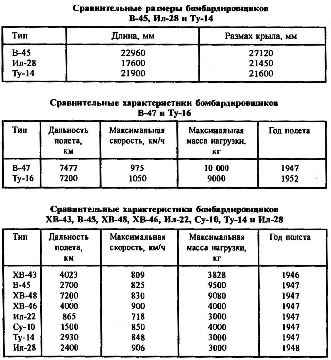
Two of the most successful machines — the bomber A. N. Tupolev Tu-14 and Ilyushin Il-28 was adopted. Its characteristics are inferior to American b-45 TORNADO only by mass maximum bomb load. The lag happened due to the smaller number of engines — the Americans put on their aircraft with four turbojet engines, and our only two. Accordingly, the geometric dimensions of the TORNADO was larger than the Tu-14 and Il-28 (see table 1).
17 Dec 1947 rose in the air American bomber b-47 swept-wing flight characteristics which were higher than any of the Soviet bombers. The main danger of such aircraft for the Soviet Union was that the b-47 was the carrier of the atomic bomb, and when they take off from European airports, it is easily reached any goal in industrial areas of the country. The height and speed of flight, the b-47 made him practically invulnerable. And the only Soviet MiG-15 able to get In-47, in December of the same year made its first test flights. She could only hope that to start serial production of the new fighter will be faster than to bring the series a huge bomber.
The explosion of the first Soviet atomic bomb “Maria” with a mass of 5000 kg in October 1949 and the advent of jet engines And L-5 (TS-3) with a thrust of 5000 kgf has opened the possibility of creating a bomber, its characteristics are superior or, at least, similar-47. The Council of Ministers of the USSR issued a decree on the establishment of the carrier of the atomic bomb—long-range bomber with two engines TS-3 designed by A. M. Lyulka, with a flight speed of 950 km/h and a range of 5,000 km with a load of 5000 kg. the Realization of the idea instructed the OKB S. V. Ilyushin.
Ilyushin began design of a bomber Il-46. Work proceeded on two ways: the first one with a straight wing, and the second with swept. The schematic design of the Orthoptera of the aircraft was completed in 1951.
At this time OKB A. N. Tupolev proactively engaged in the development of similar aircraft under the factory index “88”. The estimated maximum speed of the machine was 1000 km/h and has a range of 7000 km. the plane was supposed to use a swept wing and new engines with a thrust of 8200 kgf.
Not to mention the bomber “150”, which was developed by German constructors in KB S. M. Alekseev. It was installed on the engines AL-5, original the chassis of the bike scheme, a swept wing and empennage. The bomber “150” was calculated for a maximum speed of 970 km/h and range up to 4500 km.
Project “88” is interested in the Soviet government, and in the summer of 1950, the Council of Ministers of the USSR adopted a resolution which OKB-156 (Bureau of A. N. Tupolev) commissioned the construction of two experimental airplanes. First, the job was listed engines TR-3, then they were replaced by AM-3 with a thrust of 8700 kg. KB started developing both options.
March 20, 1951 ended the construction of the layout of the bomber, and it was examined by representatives of the air force. There were a lot of comments that are removed by 7 July 1951. The plane was distinguished by the original layout of the power plant. Two engines located in the wing roots. In an effort to reduce drag, the engine nacelles are almost pressed into the fuselage. The main landing gear retracted into the fairings, attached to the bottom of the swept wing. The bomber had a powerful defensive armament, consisting of seven 23-mm cannons. The maximum bomb load could reach up to 9000 kg.
The construction of the first prototype “88” ended in December 1951. First flight of the bomber was made on 27 April 1952. Interestingly, the first flight of a bomber designed by S. V. Ilyushin took place only a little earlier — March 3, 1952.
During the flight tests of both cars demonstrated good speed performance. The maximum speed of the Il-36 was 928 km/h, and the “88” was overclocked to 1020 km/h. Peretyagina the design of the “88” did not allow the car to achieve a given range, but high speed has convinced the military prospects of construction of A. N. Tupolev and his aircraft was recommended to serial production. In the summer of 1952, the car was given the designation Tu-16. Well, the aircraft “150”, up in the air in spring 1951, during flight testing crashed, and after it is restored.
Production of the Tu-16 was launched at an aircraft factory in Kazan. The first production aircraft delivered in October 1953. According to its flight characteristics, it was no worse than the American b-47 and maximum flight speed surpassed it by more than 100 km/h (see table 2).
The crew of the Tu-16 consisted of six people: the commander (left pilot), assistant commander of the ship (right pilot), the Navigator; a Navigator-radar operator and part-time shooter top gun mount; gunner, managing the lower gun mount; tail gunner.
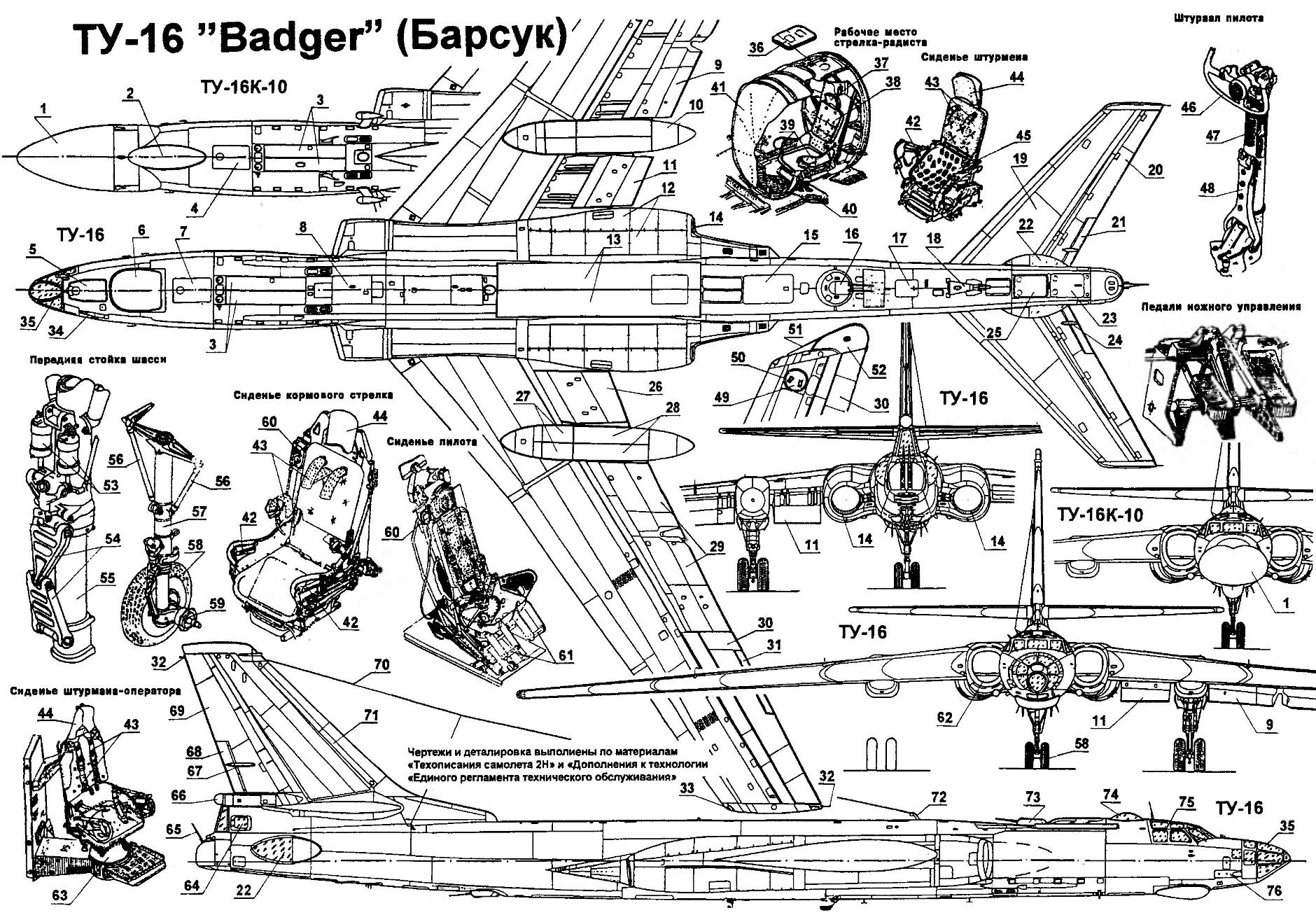
Long-range bomber Tu-16:
1 — radio-transparent Radome of the antenna of radar guidance; 2 — aerial reconnaissance; 3 — fold niche cleaning the nose landing gear (in closed position); 4 — door front cockpit (in closed position); 5 — emergency hatch of the cockpit of the Navigator; 6 — radiotransparent Radome of the radar; 7 — hatch of the front cabin crew (in closed position); 8 — emergency hatch of the cockpit Navigator-operator; 9 — outer section of the flap is in the released position; 10 — fairing (gondola) cleaning the main landing gear; 11, the inner section of the flap; 12 — the lower section of the engine hood; 13 — the bomb Bay leaf in the closed position; 14 — nozzle of the engine; 15 — the escape hatch of the cab radio operator-gunner; 16 — lower gun mount; 17 — maintenance hatch; 18 — tail safety heel (in retracted position); 19 — stabilizer; 20 — steering wheel height; 21 — the trimmer of the Elevator; 22 — blister cabin aft arrow; 23 — door of the tail cabin crew; 24 — fairing rocking the trimmer of the Elevator; 25 — escape hatch cabin aft arrow; 26 — inner section of the flap in the retracted position; a 27 — fold niches main landing gear in the closed position; 28 — fold niche cleaning truck main chassis; 29 — the outermost section of the flap in the retracted position; 30 — Aileron; 31 — Aileron trimmer; 32 — static electricity discharger; 33 — ANO; 34 — gun fairing; 35 — cabin Windows Navigator; 36 — upper hatch; 37 — headrest seats radio operator-gunner; 38 — seat radioman; 39 — pen eject; 40 — escape hatch in the open position; 41 — a sealed baffle; 42 — a firing handle; 43 — seatbelts; 44 — headrest; 45 — Cup seat; 46 — steering wheel control; 47 — column control; 48 — the emergency deviation column control; 49 — gate contact node; 50 the mechanism of the contact unit; 51 — ducky end of the fairing; 52 — additional limit spinner; 53 — vibration absorbers; 54 — dvuhsvetny; 55 — the damper shaft; 56 — brace front pillar; 57 — the front landing gear; 58 — wheel nose landing gear, the 59 — front wheel axis; 60 — time ejection mechanism; 61 —foot rests; 62 — air intake; 63 — turning the pivot chair co-operator; 64 — side escape hatch cabin aft arrow; 65 — cannon fodder installation; 66 scope, 67 — fairing traction control trimmer of the rudder; 68 — trimmer of the rudder; 69 — rudder; 70 — cable antenna; 71 Kil; 72 — mast rope antenna; 73 — upper gun mount, a 74 — blister-astrolux; 75 — the cockpit glazing; 76 — bow gun mount, a 77 — emergency section of the cockpit; 78 — GTD; 79 — wind crest; 80 is the upper section of the hood motor; 81 — castles hood motor; 82 — hinge hood; 83 — frames of the air intake duct; 84 — a air intake duct; 85 — engine mounting; 86 maintenance hatches; 87 — flame tube; 88 units fuel control; 89 — Kok motor; 90 — housing of the engine; 91 —connecting flanges of the engine casing; 92 — the interposition of the wedge of the inlet channel; 93 — main wheels; 94 truck the main chassis; the 95 — unit rack mount chassis; 96 — the cylinder of rotation of the truck main chassis; 97 — cylinder, cleaning the main landing gear; 98 — main landing gear; 99 — the axis of the wheels of the main stand; a 100 — unit mounting main landing gear; 101 — dvuhsvetny; 102 — lugs; 103 — attachment cylinder cleaning drains; 104 — the attachment points of main landing gear; 105 — knob; 106 — door in the open position; 107 stepladder in the released position; 108 — foot pegs; 109 container rescue boat; 110 — hatch the rear of the cab in the open position; 111— a safety heel to released position; 112 — fold to be fitted in the open position; 113 — fold niches nose landing gear in the open position
The equipment of the bomber allowed it to fly day and night, in VFR and IFR weather conditions.
The basis of the military complex was a radar bombopritsel RBP-4 antenna which was closed convex Radome below the forward fuselage. During the bombing, if conditions allowed, could be using an optical sight OPB-11. Tail missile installation was controlled radar gun “Argon” antenna which was over the cabin arrow.
On production aircraft have installed more powerful engines RD-3M with traction 9520 kg.
In the process of production, was released more than 50 modifications to camoletto-16 for various purposes. Here are just a few modifications.
Tu-16A (1954) Atomic bomber. Bomb Bay of the plane had a heating system. Built 453 of the aircraft.
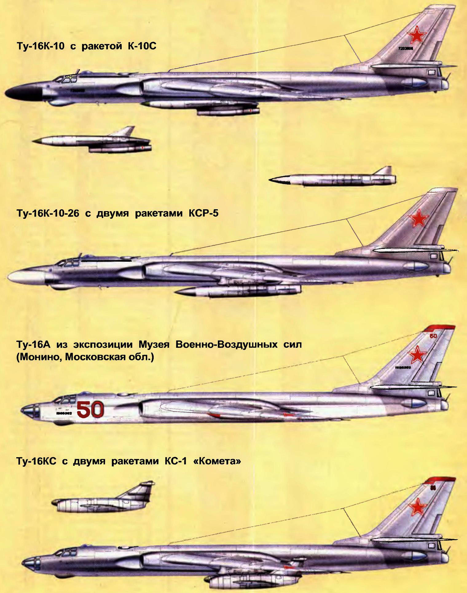
Tu-16КС (1954) the Carrier of the two anti-ship missiles KS-1, developed in OKB-155 Mikoyan by order of the Council of Ministers of 8 September 1947. Active radar homing head was developed SB-1 (Special Bureau of the Third main Directorate under the Council of Ministers) PN.Kuksenko. In may 1952, held its first unmanned launch. COP-1 had a launch weight of 2760 kg missile Length — 8.3 m, maximum diameter— 1.2 m, wingspan to 4.7 M. the Range of start — 80 km Sighting search radar “Cobalt” (similar to the American station AN/APO-13) was taken from the Tu-4КС.
Tu-163 (1955) is a Specialized tanker aircraft for Tu-16 other modifications. Was created based on the Tu-16A. The bomb Bay was installed additional fuel tank and equipment for fuel transfer. The refueling system was created on a “wing to Wing”. The hose, which transports the fuel in refueling the plane was on the left wing. In the summer of 1954 in OKB A. N. Tupolev did the basic requirements for the tanker. In total, they converted more than 100 aircraft.
Tu-16СПС (1955) jammer. In 1960, all the planes were modernized to Tu-16P.
Tu-16R (1956) photo reconnaissance. Equipment included seven cameras, a jammer and equipment electronic intelligence SRS-3 in suspension containers under the wing.
Tu-16B (1957) experimental aircraft engine test РД16 with a thrust of 11,000 kg. Characteristics of the machine were improved. Accurate data on the achievement of LTH no, but the project provided a maximum range of 7,200 km and a speed of 1050 km/h. never entered mass production.
Tu-16P (1957) jammer. In the bomb Bay of the aircraft established four station production of active interference with the protruding antennas down knife type.
Tu-16 “Tree” (1957) Director of passive noise equipped with automatic cutting and discharge of chaff.
Tu-16T (1957) Torpedo. In addition to torpedoes could carry depth bombs and air mines. In the late 60-ies, almost all of these aircraft were converted to Tu-16ПЛ search and destruction of submarines.
Tu-16S (1957) a Rescue plane. The bomb Bay was suspended rescue boat “Frigate”. She was dropped by parachute in a given area. From the side of the machine, the operator using the radio system “Speech,” let the boat directly to saving and kept it in a stable position during the landing Board and then asked the boat’s precise rate, which further supported the gyrocompass installed in the ship. The boat had a second manual control to save to be able to control the boat.
Tu-16РМ (1960) Maritime reconnaissance, based at the Tu-16K-10. Equipment allowed to conduct electronic and photographic intelligence.
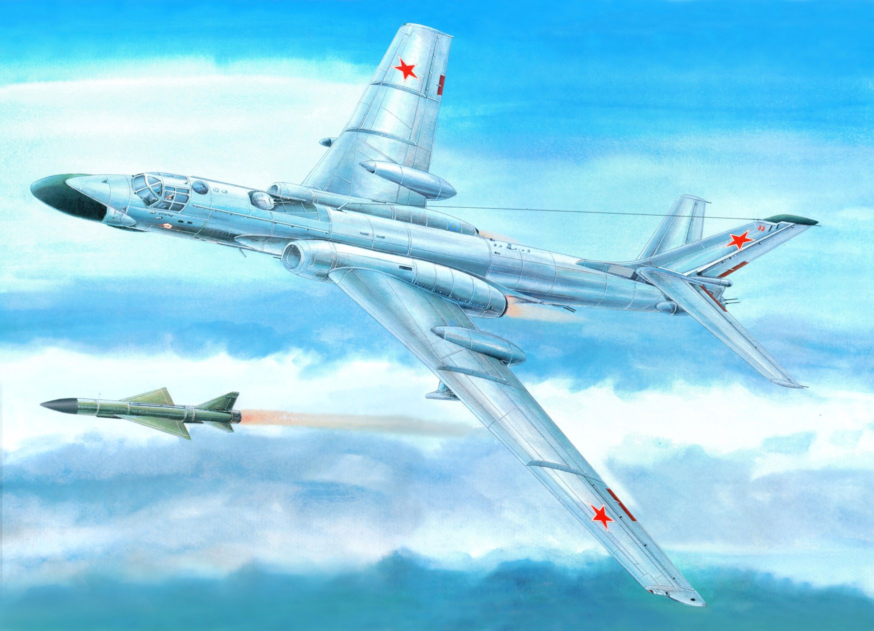
Tu-16K-10 (1961) a Carrier of one anti-ship missile K-10C, which was suspended in the bomb Bay in Palautordera position. The plane is characterized by a large fairing and targeting radars EN. The missile was developed in OKB-155. Launch range— 250 km Maximum flight speed is 1260 km/h Length— 9.5 m, diameter — 0.9 m, a wing span of 4.88 m. 22 Aug 1962 at Novaya Zemlya in the framework of the exercise “Flurry” has been tested missile K-10C with the detonation of a nuclear warhead.
Tu-16K-16 (1962) Carrier, two anti-ship missiles KSR-2. The missile was developed in OKB-155 was accepted for service in 1962. Launch range — 180 km, flight Speed is 1260 km/h, length — 8,59 m, diameter— 1.0 m, a wingspan of 4.52 m. Starting weight — 4070 kg.
Tu-16K-11 (1962) the Carrier of the two anti-radar missiles KSR-11 (option KSR-2) with a passive radar homing head.
Tu-16H (1963) Converted Tu-163 tanker aircraft Tu-22 bombers. Diagram refueling “hose-cone”. The flow of cars to the troops began in 1963.
Tu-16РЦ (1964) Plane for testing the guidance system of anti-ship missiles P-6. The missile developed at OKB-52 in 1962 for weapons submarines of project 651 and 657. Start surface. A range of 650 km and the Speed is 1400 km/h Length — 6.5 m, wingspan 2.5 m, diameter is 0.78 m.
Tu-16K-26 (1969) the Carrier of the two anti-ship missiles KSR-5, developed in the ICD “rainbow”. The missile was created on the basis of cruise missile X-22 “Storm” of class “air-ground”. The maximum launch range of 400 km. Length of 10.56 m, the diameter of the casing is 0.92 m, the wingspan is 2.6 m. the Starting mass is 5000 kg.
Tu-16К10-26 (1969) Carrier of one anti-ship missile K-10S and two anti-ship missiles of KSR-5.
Tu-16КРМ (1969) Media drone targets established on the basis of missiles KSR-2.
Tu-16РР (1970) Plane radiation survey on the basis of the Tu-16P. Under the wing of suspended containers with equipment for air sampling. It was built eight cars.
Technical description of long-range bomber Tu-16 (Filled by the Technical description and operating Instructions of the aircraft).
Long-range bomber Tu-16 is designed to apply powerful strikes on strategic targets of the enemy. The plane is made by normal aerodynamic configuration with mid-swept wings and swept tail surfaces. For technological and operational reasons, the wing, fuselage and empennage consists of a separate abutting elements and assemblies. The airframe is made of duralumin D-16T and its modifications, aluminium alloys AK-6 and AK-8, high strength of alloy b-95 and other materials and alloys.
The fuselage is semi-monocoque all-metal with a smooth working Board, supported by a set of frames and stringers of extruded and roll-formed profiles. Technologically, the fuselage is divided into five compartments: the bow the lantern f-1, the forward pressurized cabin f-2, front compartment f-3, the caudal compartment of the fuselage bomb Bay f-4 and the rear pressurized cabin. Cabs interior covered with sound and heat insulating materials.
In front pressurized cabin housed the Navigator, the left pilot (captain), right pilot, Navigator-operaor working with radiopilot RBP-4 “Rubidium” MM-P and managing fire the upper gun mount. In the rear pressurized cabin — air gunner-radio operator, ensures the connection with the land and managing fire, lower gun mount and the commander firing installations, managing fire aft gun mount and radiobeacon PRS-1 “Argon”.
The entrance to the front cabin — through the lower hatch under the seat of the Navigator-operator, and in the rear through the lower hatch under the seat of the commander firing installations. For the emergency evacuation of the aircraft, there are escape hatches from the discharged caps: for pilots, ejection up at the top of the canopy, for the rest of the crew from below under the ejection seats. Before the ejection seat pilots are moved to the rearmost position. The maximum overload during ejection is 18 V, the initial velocity of ejection — 20 — 22 m/s, which ensures safe flight of pilots over the keel of the aircraft. The rest of the crew can eject down, after throwing manhole covers under the seats. Overload in catapulting down equal to minus 3 to 5 G.
The crew is protected from the fire of enemy fighters and from antiaircraft shell fragments of artillery bulletproof glass and armor made from plates made of materials, APB-1 and ERC-2.
Under the front pressurized cabin is a compartment antenna RBP-4, closed Radome. Right behind him is a niche nose landing gear, closing two doors. Above it, mounted fuel tank, No. 1. Through the gap of access to the batteries and the front technical compartment, which houses the aerial camera AFA-33M, top gun mount, the device liquid oxygen CSW-30 for the front pressurized cabin, AC sources and other equipment. Over the compartment the container rescue boat LAS-5M to the front of the pressurized cabin. Below you can find tank No. 2, the center section with the fuel tank No. 3 with the tank No. 4. Bomb Bay is located just behind the center section. Under the tank No. 5 has a compartment for backsight signal-bombs, also closed two doors. For tanks should rear technical compartment with the lower gun mount and the device CSW-30. Above the rear pressurized cabin mounted radar “Argon”.
A swept wing (35 degrees along the line of the foci; the leading edge sweep variable). V-wing cross in the plane of the chords of 3°. Wing design douglasiana; its middle part (caisson) recruited from panels with a thick lining, reinforced stringers. From the side of the fuselage to the rib No. 12 of the caisson located inside the fuel tanks. Toe wing removable. The wing has two plug on the side of the fuselage and the rib No. 7. At the side of the fuselage the wing has a symmetrical profile TSAGI PR-C-1 OS-9-15.7% at the end of the wing — MS-11-12-12%.
The mechanization of the wing consists of odnoschelevye retractable flap, release, and cleaning which are the electric mechanisms of MPZ-GP, and ailerons, internal aerodynamic compensation is equipped with electrically controlled trim tab.
The tailplane is a cantilever, single-fin, with a sweep of 42 degrees on line tricks. Profiles horizontal and vertical tail are symmetrical. The stabilizer and fin dvuhlonzheronnoe construction, elevators and direction — a single-spar. On all surfaces provides the axial compensation; each was fitted with a trim tab with electric. The trimmer of the Elevator, in addition, has a cable control. The end fairing of the keel wood.
Chassis Tu-16 tricycle, but in addition to the front and the main landing has a tail safety support. Basic rack placed on the first outer wing and cleaned in the fairing (gondola) back on the flight. On each main rack trolley set with four wheels. On the front — two paired non-braking wheels. All landing gear equipped with nitrogen / oil dampening. Cleaning and release of the tail support is performed by mechanism.
To reduce mileage on the Tu-16 set parachute-brake system PT-16. Braking parachutes are located in a removable container at the bottom rear of the fuselage. System PT-16 provides the length of mileage on a dry concrete runway not more than 1535 m when the automatic braking of the wheels and release the parachute at the moment of touching the ground at a speed of not more than 270 km/h, weight 47 000 kg.
The power plant consists of two turbojet engines of the AM-3 with a maximum static thrust of 8750 kg. Since 1958, the aircraft are installed the more powerful engines RD-ZM thrust 9520 kgs, and since 1961 — improved RD-GP-500 with the same thrust. The motor control cable. The launch of the TRD is made from a gas-turbine starter mounted on the engine. To start using aviation gasoline B-70.
Fuel — kerosene T-1 or TC-1 — 27 is placed in the fuel tanks with a total capacity of 43 800 l At normal takeoff weight of 72,000 kg maximum refuelling is 34 360 kg. Tanks are divided into 10 groups, 5 groups for each engine. All of them (apart from tanks No. 1, 2 and 5, the fuel which is consumed in the first place) Proektirovanie and filled with a neutral gas. Fuel consumption is automatically controlled by the system of SETS-60D, the aircraft system in-flight refueling — SETS-60M. Control is a flow meter RTS-16. From the wing tanks and fuselage tanks No. 1, 2 and 5 provided emergency fuel drain.
Control system — dual mechanical hard wiring without power steering. The system main control is on autopilot. Flaps and rudder trim tabs are operated by electric mechanisms, trimmers elevators have electric and duplicating their cable mechanical control.
In the case of the bailout, so pilots are not caught in the wheel, a special mechanism rejects shturvalnaya column in the extreme forward position. When the plane is on the ground pressing both pedals turn on the braking wheels.
The hydraulic system consists of two independently operating hydraulic systems: main hydraulic system and hydraulic brake control. Nominal pressure in hydraulic systems — 150 kgf/cm2, the working fluid — oil AMG-10 with a total volume of 115 to 120 L. the Basic system is used for lifting and landing gear, opening and closing bomb Bay doors. Hydraulic brake control simultaneously provides an emergency extension and retraction of the chassis and a spare closure flaps bomb Bay.
The electrical system is designed to actuate the bomber and cannon armament, fuel pumps, fire hydrants, trimmers, radio communications and radar equipment, flaps, tail landing gear, engine start, de-icing. Is the electrical system from the primary DC system, powered by four generators GSR-18000 and battery type 12SAM-53 (reserve power source) and secondary system of single-phase alternating current supplied from two converters of the type IN 4500.
High-rise system provides pressurization and heating of the pressurized cabin of the plane the hot air, which fence is at the seventh stages of the engine compressor. The system ensures that the pressure in the cabins: at altitudes from 0 to 2000 m — ambient, from 2000 to 7250 m — constant pressure corresponding to an altitude of 2000 m, above 7250 m, the permanent drop of 0.4 kgf/ cm2. In combat, when a sharp pressure drop in the cross from the shell can be catastrophic, the drop is reduced to 0.2 kgf/cm2. The air temperature in the cabin is maintained by an automatic controller RTC-45 in the range of 16,5 — 26,5 °C.
Oxygen equipment supplier, liquid oxygen in addition to the two instruments CSW-30 for all crew members, including individual oxygen devices of the CP-16 or CP-24 and parachute oxygen instrument, KP-23.
Anti-icing system protects the leading edges of the wing from icing using engine bleed hot air. The inlet portion of the air inlets, the internal jumpers and front edge of the pipe starters have a separate aerial thermal deicing devices. Front edge of the keel and the stabilizer is equipped with electro-thermal system. Front glass lantern pilots and the sighting glass Navigator are equipped with internal electrical heating. The other glass, including blister sighting stations are blown by hot air.
Aircraft and avionics equipment provides flights in all weather conditions and at any time of the day.
Radar equipment consists of a radar bomb sight RBP-4 “Rubidium-MM-P” or better RBP-6 “Chandelier”, small radar sight PRS-1 “Argon” interrogator-responder identification system, SRZO-2M “Chrome-Nickel”, a radar transponder WITH ATC-6, the Doppler velocity meter and drift angle of DISS-1, a warning system about irradiation SPO-2 “Sirena-2”, or SPO-3 “Sirena-3”, or SPO-10 “Birch”. (The bombers used radar “Cobalt-P”, “Rubin-1”, “Rubin-1kV”, “Rubin – 1M”, “Ritsa”, “EH”.)
Radio communications equipment includes HF-radio R-807, command HF-radio R-808 R-836М “Helium”, the command VHF radio RSIU-ZM, R-800 Klen, R-802В “Oak”, or R-832 “Eucalyptus-SM”, salvage of SV-radio station AVRA-45 or R-851 “coral”, aircraft intercom SPU-10 and the tape recorder MS-61.
Provides photographic equipment to photograph the surface of the earth in the mode of “Exploration” and “Control bombing”. It includes: a set of devices, AFA-33/50m, AFA-33/75m and AFA-33/100m for daytime shooting on automatic oscillating photostroika AKUFO-156Н; set of night devices NAFA-SC/50 or NAFA-6/50 and other cameras; fotolog with two doors that are controlled by the mechanism of UR-7M; apparatus FARRELL-1 for photographing the screen of RBP-4, four shot-method PAH-457 and 13 to control the firing of gun systems.
Means of objective control. Initially, at t^-16 established a two-part recorder K2-75, later replaced by K2-713, and three-component K3-73. Since 1969, the Tu-16 was used in the magnetic recorder of the flight modes INEM-12, and then it is improved version of the MSRP-12-96.
Armament of the Tu-16 is composed of offensive — defensive bomb and gun. Normal bomb load is 3 000 kg, maximum 9 000 kg. Electroradiator, ASSOCIATED-49A provides single and serial bombs, mines and torpedoes in the entire range of altitudes and flight speeds. Aiming at bombing is done using vector-synchronised optical sight OPB-11R with the machine side of the pickup associated with the autopilot, allowing the Navigator while aiming to manage the aircraft on course. In the absence of visibility of the aiming is done with the help of radar sight RBP-4 “Rubidium-MM-P” created by OPB-11R. Gun armament consists of seven 23-mm cannons AM-23, located in the bow fixed and three mobile units with remote electric control. Shooting forward on the starboard side of the forward fuselage is a gun mount PU-88 ammunition 100 rounds. The gun is controlled by the commander of the ship, using the reflex sight PKI is mounted on a hinged bracket. Top installation DT-V7 ammunition 500 shells is the zone of fire of the horizon of 360 degrees up 90 degrees and down 3 degrees; core management practices the Navigator-operator from the top of the sighting post, auxiliary commander firing installations. Lower installation DT-Н7С ammunition 700 shells has a zone of fire on the horizon 95 degrees right and left of the axis of the aircraft in the rear hemisphere, up 2 and down 90 degrees. The main office provides the gunner with both blister posts, auxiliary commander firing installations. Aft-DC-7 with ammo-1000 rounds has a zone of fire on the horizon 70 degrees to the right and to the left from the axis of the aircraft in the rear Olustee, up 60 degrees and down 40 degrees. The primary control is exercised by the commander firing installations, support — the Navigator-operator and gunner.
Technical specifications long-range bomber Tu-16
Wingspan, mm………………………………………………………………………..33 000
Length, mm…………………………………………………………………………………… 34 800
Height, mm…………………………………………………………………………………. 10 360
Wing area, m2……………………………………………………………………… 164,65
Normal takeoff weight, kg
Tu-16………………………………………………………………………………………..72 000
To-16К……………………………………………………………………………………..76 000
Weight of empty aircraft, kg…………………………………………………………. 37 200
Maximum takeoff weight, kg………………………………………………..79 000
Maximum landing weight, kg…………………………………………… 55 000
Weight when landing on unpaved runways, kg……………………………………48 000
The weight of fuel and oil, kg…………………………………………………………..36 000
Maximum speed, km/h………………………………………………………… 1050
Practical ceiling, m……………………………………………………………. 12 800
Practical range with two UR
on underwing hardpoints, km………………………………………… 3900
The practical range
with a combat load of 3,000 kg, km……………………………………………………. 5800
Ferry range, km…………………………………………………………..7200
The length of the run, m ………………………………………………………………. 1850 — 2600
Path length, m………………………………………………………………. 1580— 1670
The length of the path with a brake parachute, m……………………….. 1120 — 1270
Maximum operating overload……………………………………2G
Performance characteristics
Wing span, m…………………………………………………………………………… 32,99
Length, m…………………………………………………………………………………………34,8
Height, m……………………………………………………………………………………….10,4
Wing area, m2…………………………………………………………………….. 164,65
Weight of empty aircraft, kg………………………………………………………… 37 200
Normal takeoff weight, kg…………………………………………………. 72 000
Maximum takeoff weight, kg………………………………………………. 79 000
The maximum flight speed, km/h……………………………………………..1050
Cruising speed, km/h……………………………………………………………..850
Practical ceiling, m…………………………………………………………… 12 300
Combat radius of action, km……………………………………………………………5925
The maximum range
without refueling, km……………………………………………………….7200
Maximum payload, kg………………………………………………9000
N. Food reserve was, A. CHECHIN, Kharkov
Recommend to read
 RACING MODEL — THE CHAMPION OF EUROPE
In the early 70-ies before the Soviet athletes-automodellista was a challenge: dvuhsotmetrovy to exceed the threshold speed in the class of models 2.5 cm3. These days, the speed has... WORKING SLED
As soon as the first snow fell, it became clear that the house has no need of such cargo winter vehicle as a sled. Child's sled for a long time "went" on a well-deserved rest in a pile...
