 Photoswitch is a widespread element in various automatic systems, protective devices, meters, etc. depending on the tasks the system is triggered by a photocell can be made instantly (for example, the turnstile in the subway), or via a predetermined gap (the Elevator doors). And in some cases rapid changes in illumination is necessary to analyze the situation and prevent deployment if it turns out to be false.
This problem is not new, and in the technical literature there are several works devoted to its solution.
We offer a light barrier with increased protection against false positives based on the scheme presented in the material V. Holasova “Photocell” in the journal “Radiomir” № 7, 2001.
My scheme was simplified and modified. According to the wiring diagram generated PCB manufactured and tested her prototype. The tests demonstrated a good operation of the device, and the changes made were as follows.
Instead of two operational amplifiers, which require bipolar power and output level Converter, to align with “logic” I set the comparator КП544САЗА, powered the circuit from a stable unipolar source, removed level Converter and added to the scheme a delay the operation of the comparator after switching on 2 on transients (this delay can be excluded).
The digital part of the circuit remained unchanged. In the scheme based on the following algorithm to protect against false positives:
— hysteresis threshold of the light barrier, that is, light beams on and off, different;
— after power on the photocell comparator is triggered immediately, but after 2;
— exposure time delay or disable the photocell is 5-15 minutes (if desired, can be changed up or down) re-start (reset) with a relatively quick (less than 5-15 minutes) fluctuations of the light near the threshold, for example, by passing clouds or the occasional lighting in the headlights. In this case, the photocell may not change half an hour—depending on the duration of the interference.

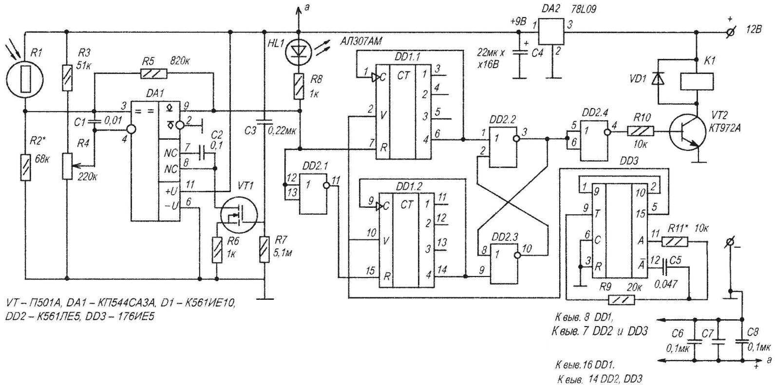
A circuit diagram of a photocell with increased protection against false positives
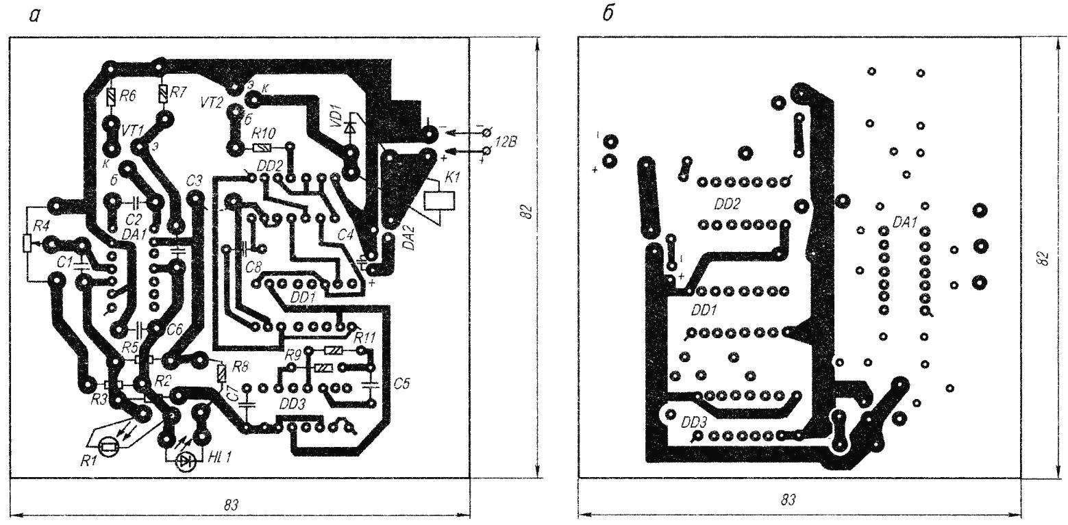
Location details of circuitry on the PCB (a) and its reverse side (b)
Diagram photocell are shown in figure 1. On-chip DА1 collected a threshold device with hysteresis, which depends on the value of the resistor R5. The threshold of the photocell is set by the variable resistor R4. Transistor VT1 is collected by the operation delay of the comparator after power, which depends on the capacitance of the capacitor C3 and resistor R7.
The capacitor C1 is protected from interference, C2—protection against self-excitation of the comparator at high frequencies. Led НL1—indication of tripping of the comparator, for ease of installation of the threshold of the light barrier. DА1 output signal is supplied to a digital one-shot, assembled on the chip DD1, DD2. The pulse generator with frequency divider is assembled on the chip DD3. The oscillator frequency can be changed by resistor R11. On the chip DD1 and logical elements of the “2” or “no” (DD2) collected additional frequency divider with control logic and circuits are reset.
For high illumination of the photoresistor R1 output DА1—”1″ level and a meter DD1.2. After the 8th pulse from DD3 at the output of the counter is fixed to “1” and a trigger on DD2 turns off the actuating relay K1.
To reduce illumination DА1 comparator switches from “1” to “0”. The meter DD1.2 is reset and begins to count DD1.1. After the 8th pulse from DD3 at the output of 6 DD1.1 fixed high level, and the trigger on DD2 goes when through the open transistor VT2 relay K1 and thereby includes lighting lamps.
If the count time (5-15 min) switches the luminance level (for example, due to the movement of the clouds), then the counter resets and the relay does not change state. Again begins the countdown of the delay time. This provides protection from interference.
Setting of the light barrier is the selection of resistor R2, its value depends on the photoresistor R1 and the necessary extent of regulation needed when the resistor R4. The selection of the resistor R11 exhibited the desired latency, as shown, in the limit of 5-15 min.
When setting up instead of a conclusion “5” DD3 to the inputs of counters DD1 is possible to connect the output “1”: then the exposure will be reduced to 64 times.
All constant resistors — MLT-0,125, variable — R4-SP-1 or another appropriate. The oxide capacitor C4—C50-6. Capacitors C3, C5—K73-17. Capacitors C1, C6, C7, C8-KM. The photoresistor almost any, e.g. PSS-4, СФ2-19.
Printed circuit Board made of the bilateral foiled fiberglass.
V. GRICHKO, Krasnodar
Recommend to read
 A VERY OLD FRIEND
City bus ZIL-158. In the postwar years for urban transportation used mainly the bus ZIS-155, which was produced from 1949 to 1957. But in the mid fifties it became clear that these... NOT WORSE THAN THE CONDITIONING
I have developed a mini system is to automatically maintain the desired temperature and air humidity in the oven, covered boxes, as well as in greenhouses or other spaces. The design of...
