
 Flight tests of the “Skimmer Zimmerman” was still in full swing, and BuAir has developed a specification for carrier-based fighter based on this unusual aircraft. In September received an order for two prototypes of the fighter.
The lead engineer on this project was appointed E. Greenwood. Full-size wooden mock-up of the fighter, designated F5U, team Greenwood finished in late may of 1943 and June 7, presented his naval Commission.
Fighter differed from its predecessor flying the V-173. The first thing that caught my eye — two powerful engine Pratt & Whitney R-2000-7 with a capacity of 1350 HP For efficient cooling in the wings were provided with two large circular air intake is located they the fan blows air into the motor compartments. The exhaust air coming out through adjustable louvers on the top and bottom surfaces of the wing.
The placement of the pilot in the cockpit F5U was more rational than in the V-173 is now he was located in the forward compartment acting cylindrical section, which is closed by the large teardrop-shaped lantern. To improve visibility down to the floor of the cabin provided for the glazing.
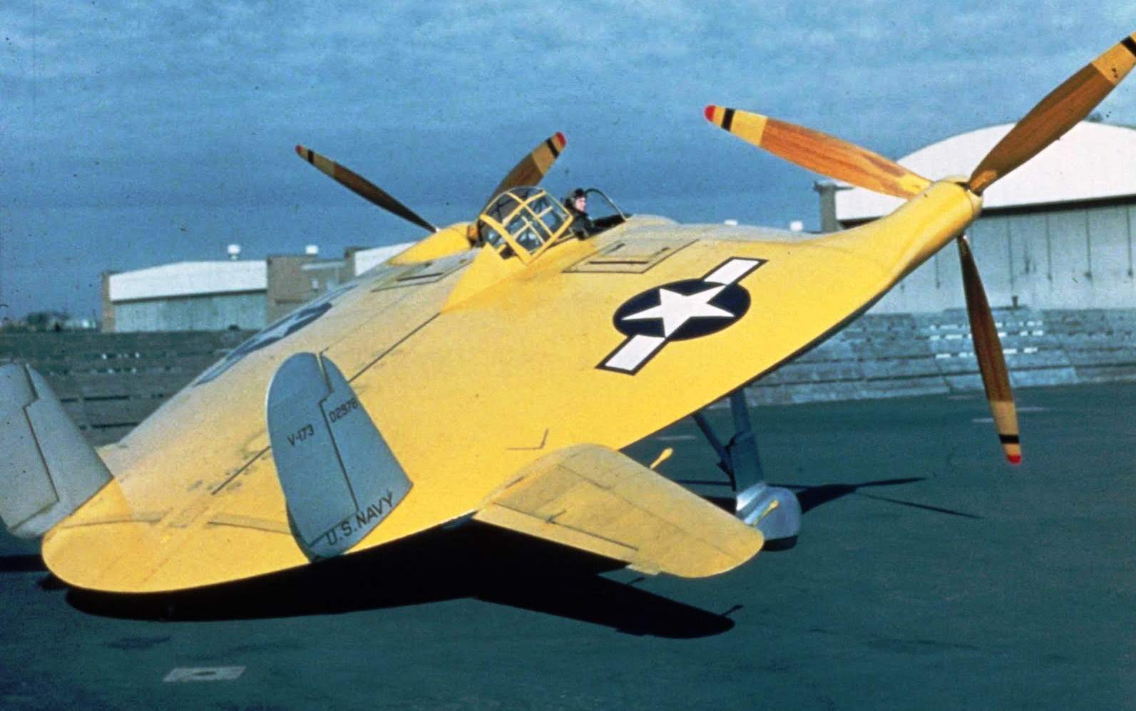
Propellers fighter had a smaller diameter than the V-173, which allowed to reduce the Parking angle of the aircraft by nearly five degrees. Since the plane was designed for deployment on the deck of an aircraft carrier, it was equipped with the brake hook for hooking over the cable arresting gear. Mandatory requirement for carrier aircraft was built-in steps or ladder for boarding of the pilot in the cockpit — the use of ladders, step ladders, as it was on /-173 on the pitching deck of a ship is strictly forbidden. F5U for the design of such devices proved to be quite challenging because its cabin is at a height of over three metres above the ground. However, Zimmerman is, as always, found a very original solution. To sit in the cockpit F5U, the pilot had to move the car back and the back of the plane, setting foot in special ledges, climb into the cockpit.
Normal calculated takeoff weight of the aircraft reached 7200 kg, making it one of the heaviest carrier-based fighters in the United States (F4U — 5700 kg, F6F — 6900 kg, and twin-engine 000 kg).
Basic controls — gorizontalnyj all-moving stabilizer and two keel with rudders. In the rear of the unit was the two automatic flap to fight the ground effect during landing. The latter’s work was already tested on the V-173. Military recommended to check and all-moving stabilizers that were made by Zimmerman in October 1943. The stabilizers of the V-173 was converted by type F5U, and upgraded the car made a successful flight on 22 October 1943.
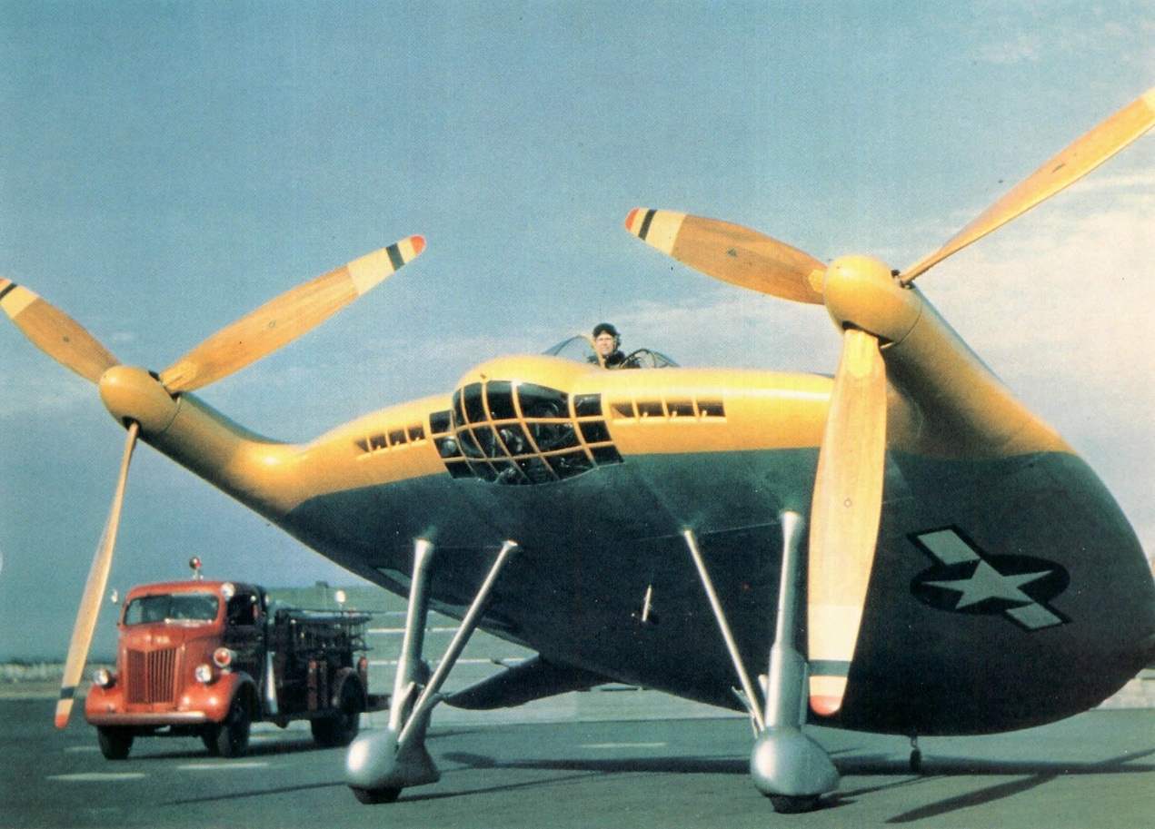
XF5U-1 with screws from Corsair fighter PA gazovojj site
Special attention during the design applied to the air screws. The model shown to the military, were equipped with temporary props that have nothing to do with the real — they just had yet to develop. Therefore, project approval was delayed until after the development of the whole power plant.
The developers of the screws had to deal with several serious problems. The first problem lay in the mechanism of transmission of torque from the engines to the screws and the synchronization of their rotation — it was decided though simple, but not effectively enough — with the help of the installation gear and the long shaft of square section. Experienced large loss of capacity, and the reliability of this scheme was low as the failure of at least one of the gears leads to the complete loss of control.
The second problem was. what blades experienced more stress caused by the asymmetric flow around the propeller at high angles of attack. At least this could lead to strong vibration, and even to the destruction of the screw. When this task himself, Zimmerman could not find an acceptable solution, while in November 1943, he was not up with the bright idea to make the screw of the two pairs of blades with variable cyclic pitch of each pair. New screw called balanced propeller. Thanks to swash the pilot could tilt the disc of the rotating propeller in any direction at an angle of 10 degrees, thus reducing the load on the blade and deflecting the thrust vector of the propeller. Interestingly, a similar system was previously used only on helicopters. For F5U, already promising to be a maneuverable fighter, the use of a swashplate can make it highly maneuverable and virtually invincible in battle. The final draft of the F5U in that form — with balanced propellers, were approved.
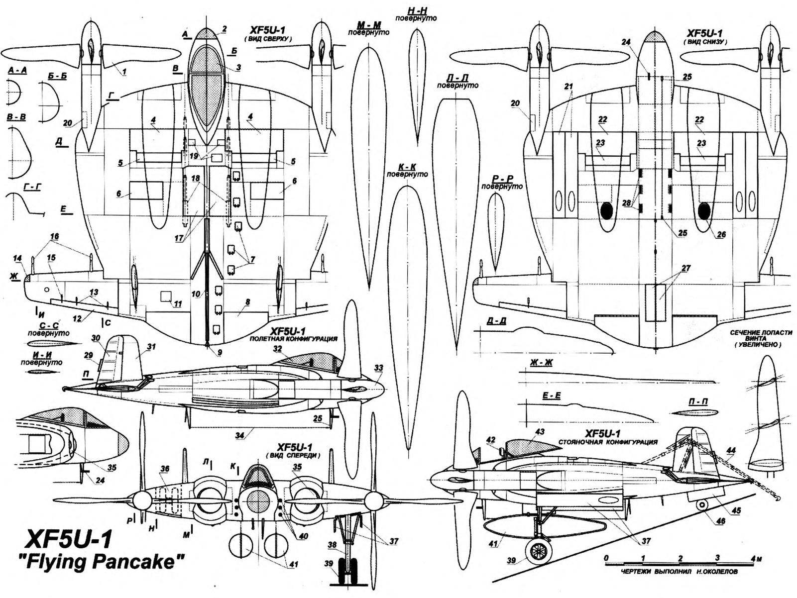
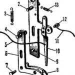
Carrier-based fighter XF5U-1:
1 — four-bladed variable-pitch propeller; 2 — glazed front compartment; 3 — canopy canopy; 4 — top maintenance hatches engines; 5 — the upper sash of the engine cooling system; 6 — cover cartridge compartments; 7 — spring cap stairs; 8 — flap; 9 — planting the SJC; 10 — rod landing hook; 11 —maintenance flap control system flap; 12 — trimmer elevon; 13 — thrust elevon trim; 14 — ANO; 15 rocking trimmer elevon; 16 — balance weights; 17 — maintenance hatches and machine gun ports; 18 — the place of installation of machine guns; 19 maintenance hatches; 20 hatch access intermediate gear; 21 — fold niche of cleaning the main chassis; 22 — lower maintenance hatches engines; 23 — the lower sash of the engine cooling system; 24 — LDPE; 25 — rod antenna; 26 — the exhaust pipe of the engine; a 27 — fold niche cleaning tail wheel; 28 — a Windows hiltonbritney; 29 — trimmer of the rudder; 30 — rudder; 31 Kil; 32 — sliding part of the canopy; 33 — spinner; 34 — antenna cable radio stations; 35 — the air intakes for the engine cooling system; 36 — niche landing gear; 37 — fold niche of cleaning the main chassis in the open position; 38 — front of the main chassis; 39 — main wheels; 40 guns; 41 — external fuel tanks; 42 — the pilot’s seat; 43 — movable part of the lamp in open position; 44 — rod brake hook in the working position; 45 — fold niche cleaning tail wheel in the open position; 46 — the tail wheel
Ejection seat JD-1 Martin-Baker
In March 1944, it began the construction of two prototypes: one of them was intended for static tests, the second —for flight. 15 July 1944 to facilitate the financing of the program of flight tests of the V-173 and XF5U construction combined.
The first instance of the XF5U-1 was rolled out of Assembly plant August 20, 1945. The test aircraft was planned to take place in late 1945 at the airbase Muroc. For this experimental car was loaded onto the ship and through the Panama canal to deliver on the West coast. However, these plans were not realized. After the defeat of Germany started a review of all military programs of the United States with a view to their reduction. Not paid attention and company Vought. 24 may 1945, the firm was financial audits. The financiers of the fleet noted that the program “Skimmers Zimmerman” has already cost taxpayers $ 250 million, but the achievements were more modest.
The audit resulted in a substantial reduction of funding for the program, and free up funds were aimed at the development of aircraft jet engines. Lack of funds led to a delay in the supply unloaded screws with cyclic pitch control, which is made firm Hamilton Standard Hydromatics.
In February 1947, the copy of the flight had to temporarily put the screws from istrebitelya F4U Corsair. To spend at least ground testing of power gearboxes installation and trial run, the blades of the left propeller mounted in reverse position. This is clearly seen in photos of the aircraft with the logos of the company Hamilton on the blades of screws: on the left they are on the back sides of the blades, and on the right — front.
Ground testing gazovka and taxiing of aircraft, conducted test pilot B. Guyton, have been quite successful. After delivery of standard screws and mounting the aircraft is prepared for loading onto the ship for transport to the base Muroc. However, on March 17, 1947 programme for the creation of the fighter F5U closed. The Navy lost interest in piston fighters, because the sailors has already had more promising jet fighter — FH1 Phantom, the F6U Pirate and FJ1 Fury. Aircraft XF5U-1 was decided to utilize.
Cabin deck fighter XF5U-1:
1 — voltmeter; 2 — watch; 3 — speed indicator; 4 — landing gear position indicator; 5 — radio; 6 — altimeter; 7 — magnetic compass; 8 — the pointer of the engine speed; 9 — temperature gauge of the engine; 10 — gauge; 11 — variometer; 12 — gauge fuel pressure; 13 — alarm emergency remaining fuel; 14 — tachometer; 15 — warning the remainder of water; 16 — gauge slip and roll; 17 — the attitude indicator; 18 — pressure gauge in the hydraulic system; 19 —Crank engine starting; 20 — ORES; 21 — arm-rest; 22 — handle of manual fuel pump; 23 — arm of the retract chassis; 24 — controls, flaps: 25 — oil pressure indicator; 26 — switch firing mode; 27 — switch of the fuel pump; 28 — control wheel trim of the elevons; 29 — switch fuel tanks; 30 handle coordination of the work of engines; 31 — stick to change the pitch of screws; 32 — handle rudder elevons; 33 panel radio equipment; 34 — gas station electrical system; 35 control cabin lighting; 36 — microphone Jack; 37 — battery switch
In conclusion, a few words about the publications, which focuses on allegedly classified flight test XF5U-1, the secret series production, and the installation on the car of jet engines. Meet and even more intriguing stories, for example, about the relationship of these planes with UFOs, etc. Documentary evidence of this, I may say, the “facts”, the authors could not be found. However managed to find almost criminal details of the disposal of two aircraft built.
With the first instance of the XF5U-1 to part was the easiest — it was almost destroyed in static tests, and workers had to cut the design of cutting torches. The task of the destruction of the second aircraft requested the head of the experimental Department of the company Vought L. Stetson, who led the Assembly of aircraft and knew how to break “Skimmer Zimmerman”. First plane took off, the engines and avionics, and then drove it under the crane with a suspended iron ball. After a few blows, the car turned into a pile of debris that had been on the market for local buyers of scrap.
After a few days the representatives of the Navy addressed to the firm demanding the return of money from the sale of scrap metal, including 6000 dollars for a few panels of pure silver that was used in gearboxes screws. Some time working unsuccessfully through the remaining debris in search of precious metal, and as a result the company decided to just pay the required amount and not to waste time.
Buyers of scrap turned out to be more efficient. Finding silver, they turned to a local jeweler. He saw a suspiciously large quantity of the precious metal, reported to the police. Buyers were arrested and handed over to the agents of the local branch of the FBI. When representatives of the firm Vought confirmed the legality of the transaction, the incident has been exhausted and buyers were released. Here’s a detective was at the end of the story of the aircraft that Charles Zimmerman.
The design of a fighter F5U-1
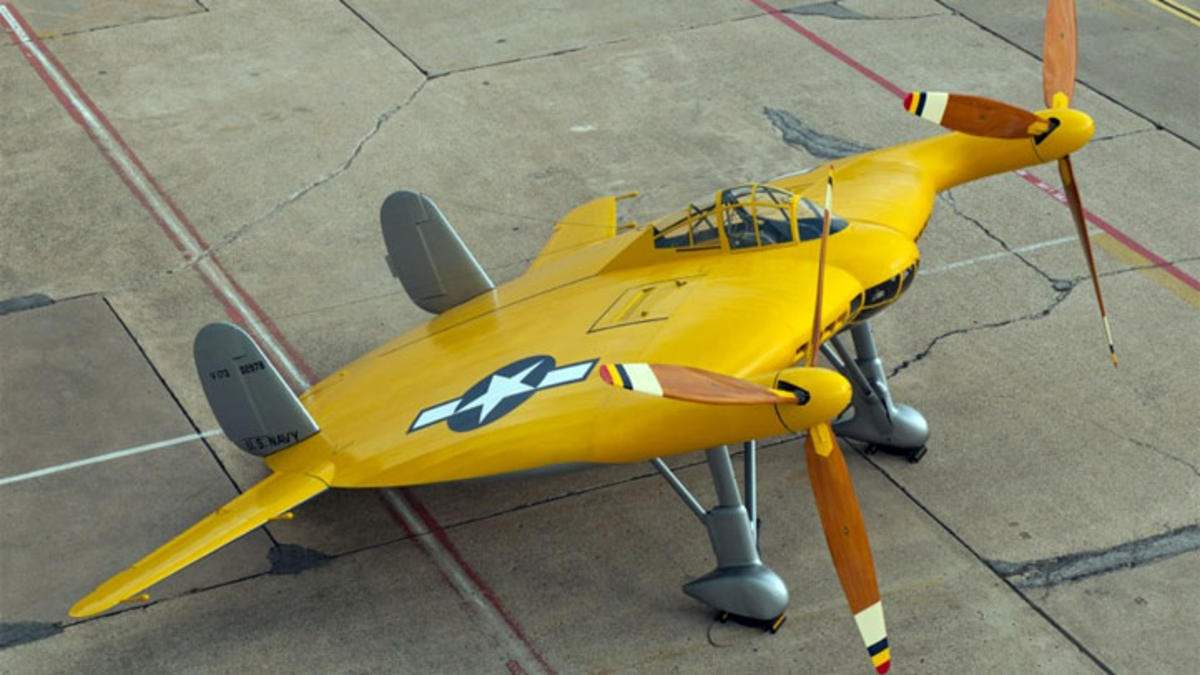
Fighter XF5U-1 was a monoplane dvuhkilevoe integrated layout with an elliptical wing symmetrical NACA 0015 profile across the span.
Structurally, the aircraft consisted of three main parts: the front, middle and back. In front was the cockpit, air intakes with fan forced cooling of engines and compartments with small arms. The middle part of the fuselage was formed of two power frames-the side members, between which were located the engines, main and service tanks, shafts and gearboxes drive the screws. In its lower part to the front power frames were attached the main landing gear. In the back were the main controls of the aircraft, the tail wheel and brake hook.
Power set design is produced of aluminum alloys and cladding of a new composite material — metalit patented by Vought and firm which is a glued and molded in a large autoclave is a sandwich of two thin aluminum sheets separated by a layer of ultra-light wood — balsa. The strength and stiffness of the resulting material gave an opportunity to radically reduce the number of supporting aircraft frames and ribs, making the design almost monocoque.
The cockpit is sealed, a closed teardrop sliding canopy. Drive the sliding part of the electric lantern. Seat pilot ejection, type JD-1, production of the British company Martin-Baker. On the front panel of the dashboard main navigation devices, devices of control systems of aircraft and power plants. On the left panel has a handle engine control, cyclic pitch propellers, trimmers, chassis and brake hook. The right panel was occupied by a gas station and a control panel by the radio station.
The power plant consisted of two 14-cylinder double row Pratt & Whitney engines R-2000-2(D) Twin Wasp with a capacity of 1600 HP On the front of the crankcase of each motor was fixed bevel gears that transmit torque to a single cross-shaft screws. In addition, the gearbox connects the engine cooling fan. Exhaust the hot air out through adjustable louvers on the lower and upper surfaces of the fuselage. Exhaust gases through the manifold and a U-shaped exhaust pipe were derived under the fuselage. In case of failure of one engine, the pilot could disable it from the gearbox, using the appropriate clutch. Screws aircraft — variable General and cyclic pitch. The blades were made of wood.
Landing gear tricycle tailwheel. All two-wheeled landing gear. System cleaning hydraulic. Large Parking angle of the aircraft forced the constructors to secure the brake hook on the upper surface of the fuselage. The mechanism of release and cleaning hook hydraulic, pyramidal type.
The aircraft control system mechanical, hard. The roll and pitch of the machine was managed by differentially deflected all-moving stabilizers. Stabilizers are equipped with trimmers and external weight compensators. Stabilization of the aircraft in the direction is provided by two trapezoidal fins with rudders large area. In the tail of the plane had automatic flaps used during landing to parry “ground effect”.
The radio equipment of the fighter consisted of a short-wave radio and radio. Antennas these devices were located under the fuselage. On prototypes XF5U-1 armament was not installed. Production vehicles provided to equip six 12.7-mm Browning machine guns with ammunition at 400 rounds or four 20-mm guns M-39. Under the fuselage can be installed two pylons to mount bombs weighing up to 454 kg or fuel tanks with a capacity of 568 L. the Use of rockets or dive bombing was completely excluded due to the large diameter of the screws.
The estimated lesotekhnicheskii characteristics of a fighter Chance Vought XFSU-1
Engines……………………………………Pratt & Whitney R-2000-2 (D) Twin Wasp
The engine power, HP……………………………………………………………..2 x 1600
Weapons…………………………….— 6 12,7-mm Browning MG 53-2 machine guns
with ammunition at 400 rounds for each gun
— 2 454-kg bombs
The length of the plane, mm…………………………………………………………………………… 8720
Height, mm…………………………………………………………………………………………4500
The diameter of the propeller, mm………………………………………………………….4880
Scale, mm
given stabilizers……………………………………………………………….. 9900
given screws
the diagonal position of the blades…………………………………………….. 9680
— subject screws
IRI cruciform position of the blades………………………………………….. 1110
Parking is fragile…………………………………………………………………………….180 43′
Wing area, m:…………………………………………………………………………..44,129
Normal takeoff weight, kg…………………………………………………………..7620
Maximum weight, kg…………………………………………………………………….. 8581
Landing weight, kg…………………………………………………………………………. 7050
The supply of fuel in internal tanks, l………………………………………………..1060
Fuel in external tanks, l……………………………………………………..568
Maximum flight speed at maximum (emergency) engine km/h
— at sea level………………………………………………………………………. 584 (634)
— at the height of 3000 m…………………………………………………………………….645 (694)
Minimum flight speed, km/h
— under normal engine power……………………………………………..169
— with a full load and maksimalnoi power…………………………..74
The rate of climb, m/s
— under normal engine power………………………………………….11,18
— at maximum engine power………………………………………..15,6
— in emergency mode engine…………………………………………..20,06
The climb at normal engine power, min.
— 3048 m………………………………………………………………………………………………4,9
— 6096 m…………………………………………………………………………………………….11,1
The take-off distance, m
— when the wind 0 km/h………………………………………………………………………………283
— when the wind 28 km/h…………………………………………………………………………….207
— with winds of 46 km/h…………………………………………………………………………….158
The ceiling, m…………………………………………………………………… 9754
The maximum duration of the flight at sea level, h……………..4,26
The maximum range
at a cruising speed of 380 km/h, km……………………………………………1465
N. Food reserve was, A. CHECHIN
Recommend to read
 THE STARTING HOOK
New simplified design of the tow hook works just as reliably as the best modern designs, providing easy control model glider when you search for updrafts and good acceleration apparatus...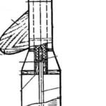 WINNING “SKYSCRAPER”
The proposed model is a vivid example of technical creativity of Moscow's leading athletes-taketomo-delicto that three years in a row became Champions of Russia in this category of...
