
 (The end. Beginning in № 3’02)
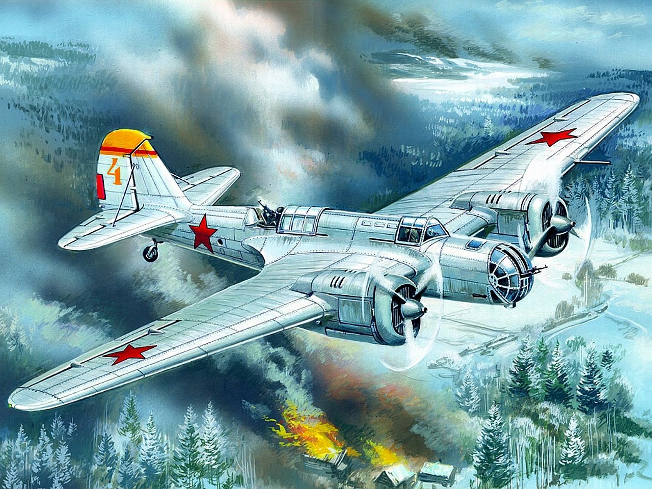
The plane SB (ANT-40) — high-speed bomber, made of a metal cantilever monoplane with two engines M-100A located on the wing.
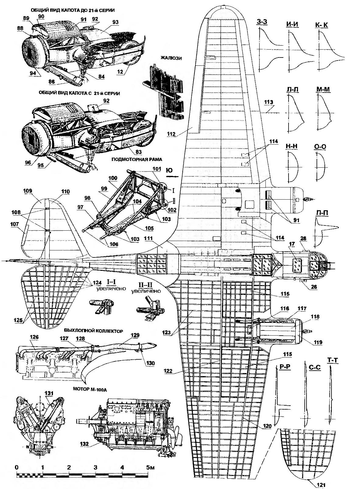
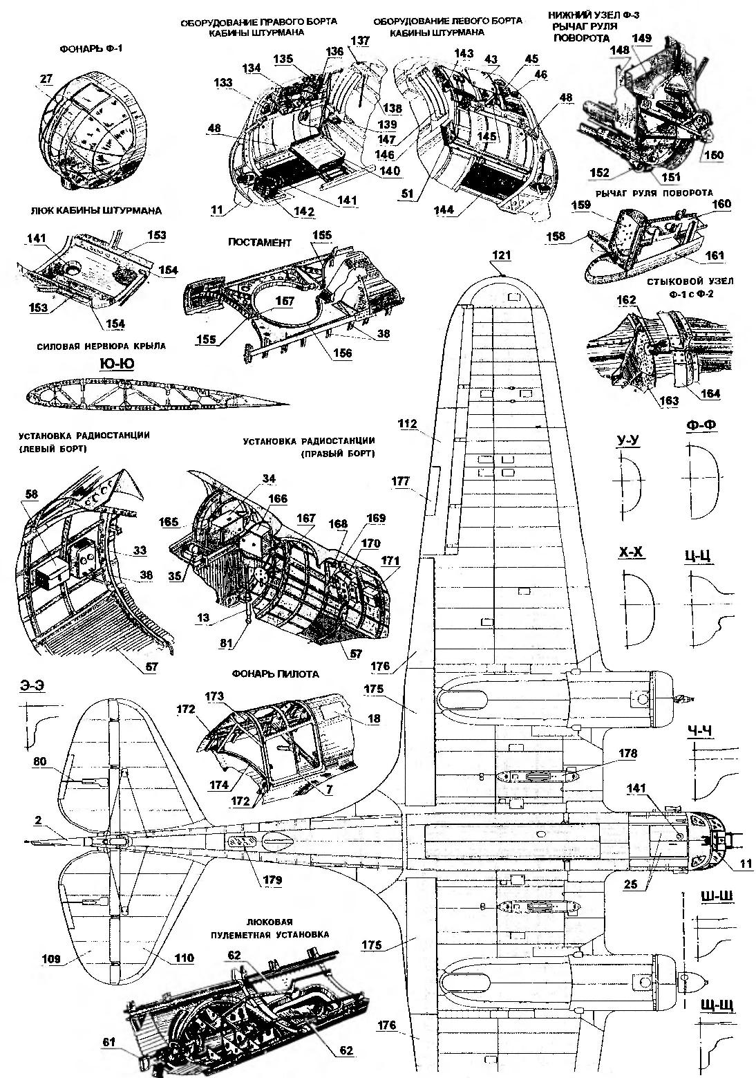
The fuselage is relatively narrow, oval-shaped cross section, narrowed at the top, cigar-shaped, like the monocoque; for convenience during transportation and the repair is partitioned into a number of separate aggregates: f-1 — head part of the fuselage is aerodynamically shaped forms, was a Navigator; f-2 — the second compartment of the fuselage is a cabin with a lantern to wrap the head of the pilot; C — center section, represents the middle part of the fuselage and wing and is a power basis of the aircraft as it will link the wing and fuselage and, in addition, carries both propeller installation aircraft, the petrol and oil tank, chassis, middle part of the landing flaps and cargo compartment. Power set centroplane part of the wing consists of two spars connected by ribs and stringers; f-3 — the tail section of the fuselage carries the tail unit of the aircraft and spike installation. In this part of the fuselage contained the radio operator’s cabin; — detachable, cantilever part of the wing. They hung the ailerons and the landing flaps. Inside the console parts of the wing placed fuel tanks.
The wing consists of a center section and detachable parts. Last met and the center section, dvuhkonusnyj, truss spars have upper and lower belt, made of telescopically recruited hromansilevyh pipes, connected by bracings, struts and plates. The ends of the outer wing truss spar goes into the beam. A smooth-running wing skin is reinforced by the often established rare ribs and stringers.
Tail — raskalennoi, consists of a keel, R-4, rudder R-3 streamer, stabilizer R-1 and elevators R-2 with their trimmers. Kiel, R-4 with the fuselage of the f-3 are structurally one. The remaining units of the tail — plug.
To improve the aerodynamics of the aircraft at the junction of the fuselage with the wing, stabilizer and fuselage on the leading edge of the wing in places hood is installed fairings-fairings.
Landing gear with oil-air cushioning, the retractable type with provalone brake wheels 900×300 mm. the Mechanism of the landing gear of the hydraulic type with electric alarm. In case of damage of the hydraulic system in flight has an emergency cable descent driven by a hand winch mounted in the cockpit the radio operator (this duplication is vital to the aircraft systems was made in the USSR for the first time). The wheels retract into the wing back, but part of it completely. So the chassis has a cowl-fairing of the sliding type, which at the time the landing gear is formed by a mechanism associated with the moving elements of the mechanism, and closes all the speakers from the wing parts. To reduce run of aircraft landing wheels are equipped with drum brakes with pneumatic control.
In order to reduce landing speeds, and increase the steepness of the trajectory planning on the aircraft is provided with landing flaps type “Northrop-shrink”. Flaps consists of four subunits: two mounted on the center section and two cantilever part of the wing.

High-speed bomber SB-2:
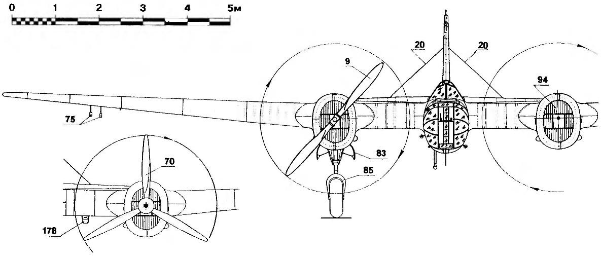
1 — the trimmer of the rudder; 2 — rudder; 3 — weight compensation of the rudder; 4 — keel; 5 — the blisters of the cab radio operator-gunner; 6 — sliding canopy arrow; 7 — sliding canopy of Milota; 8 — visor of the cockpit; 9 — bladed metal screw type TSAGI; 10 — twin ShKAS machine gun; 11 — fairing Gilsonite; 12 — wheel main landing gear; 13 — outer pipe of cable release of the broadcast antenna; 14 — cabin Windows, arrow-radio operator; 15 — fairing of the control rod of the rudder; 16 — thrust of the rudder; 17—open astrolog cabin of the Navigator; 18 maintenance hatches; 19 — root rib of the wing; 20 — brace stabilizer; 21 — pull trimmer of the rudder; 22 — Luke lower machine gun; 23 — footrest; 24 — fold of the bomb Bay; a 25 — fold cabin entrance hatch of the Navigator; 26 — Venturi tube; 27 — the cabin Windows of the Navigator; 28 — cover the cab of the Navigator; 29— power set of the rudder; 30 — power set of the keel; 31 — the root rib of the stabilizer; 32 — turret ShKAS machine gun; 33 — the switch Board; 34 receiver stations; 35 — unfair RUNES-10; 36 — spars; 37 air cylinders start system engines; 38— frames; 39 — the pilot seat; 40 — steering wheel controls Elevator and ailerons; 41 — instrument panel; 42 — fur pneumopathy; 43 — portfolio Navigator; 44 optical bombsight ОГ1Б-1 in the stowed position; 45 the apparatus of the aircraft intercom SPU-3: 46 — three-color alarm; 47 — girlsoutwest; 48 — cartridge boxes; 49 — a box for storing tools; a 50 — seat Navigator; while 51.58 — first aid kits; 52 — pedal foot control rudder; 53 — oxygen tank pilot, 54— the inner tube of the release of the radio antenna; 55 — seat radioman; 56 — oxygen tank radio operator-gunner; 57 — corrugated cockpit floor is the arrow-radio operator; 59 — the emergency landing gear; 60 — parachute rocket PAR-13; 61 — lukovoy gun ShKAS; 62 a frame mounting a machine gun; 63 — amortization cords stand castilnovo wheels: 64 — spike wheel; 65 — front spike wheel; 66,67,68 — hinge of the rudder; 69— guide chute cockpit the radio operator; 70 three-blade variable-pitch propellers VISH-2; 71 — COC propellers-2; 72 — operating the rear hatch; 73 — top bonnet; 74 — sliding part of the cockpit canopy in the open position; 75-underwing flares 76—lantern radioman; 77 — turret; 78,121 – dimensional ANO; 79 rocking the trimmer of the Elevator; 80 — rod trimmer rudder; 81 — plumb the cable of antenna; 82 — fold of the bomb Bay in the open position; 83 — fold nish cleaning the main chassis; 84 — strut main landing gear; 85 — fork racks wheels; 86 — hinged bottom hood; 87 — fold cabin entrance hatch of the Navigator in the open position; 88 hood; 89 — deflector; 90 — front ring; 91.94 — blinds; 92 hood to the neck of the oil tank; 93 — bonnet; 95 hatch cover; 96 — thunder; 97,105 — beam engine mounts; 98 semi — circular bar; 99—long brace motor; 100 — short strut; 101—upper attachment points of the strut engine mounts; 102 node of the lower belt; 103 — mount hoods: 104— fibre strip: 106 — mounting brackets radiator; 107 — trimmer of the Elevator; 108 — the hinge of the Elevator; 109 — the steering wheel height; 110 — stabilizer; wing fairing 111; 112 — ailerons; 113-tube “PITO”; 114—hatches access to the filling necks of the fuel tanks; 115—fuel tank 116 to the oil tank; 117 — exhaust manifold; 118—engine M-100A; 119 — water radiator; 120 — front side member; 122 — rear spar; 123 — rib of the center section; 124 — the power range of the stabilizer; 125 — power set handlebar height; 126 — front exhaust manifold; 127 — a rear exhaust manifold; 128 — ears swivel; 129—trumpet; 130 — retaining strap; 131 — block; 132 — crankshaft; 133 — watch ECHO; 134 — navigation panel Navigator; 135 — oxygen device; 136 — a box of signal rockets; 137 — sucker oxygen plant; 138 — box sextant; 139 — oxygen tank; 140 — sliding seat Navigator; 141 — heel installation OGB-1: 142 — compass an-4; 143 — slot fastening heel OPB-1; 144 — fold access door; 145—bracket OPB-1; 146 wall-box; 147 — a door box; 148—; 149 — otkrepitelnyh rib; 150 — node hinge of the rudder; 151 — welded tubular node: 152— fin mounting braces stabilizer; 153 — rails; 154 — beam of fastening of the flaps of the hatch; 155 — trim; 156,157 — ring; 158 rocking of the rudder; 159—spar; 160 — rib; 161—plating of the rudder; 162—a connecting bolt; 163 — compartment f-1 fuselage; 164 — compartment f-2 fuselage: 165 — umformer RUNES-120; 166 transmitter; 167—antenna winch; 168 handle budenovskogo management; 169—voltmeter; 170 duplex flap; 171 — tool kit; 172 — shoes attach the flashlight to the side rail; 173 — handle lantern; 174 — profile base of the lamp; 175 — brake center section (“Northrop — shrink”); 176 — brake outer wing; 177 trimmer Aileron (right only); 178— hardpoints larger bombs (only in the later series); 179 — the lower cabin Windows, arrow-radio operator
Control of aircraft is accomplished by using a normally located elevators, rudder and ailerons. The rudders hard and ailerons mixed — rope and hard. To reduce effort in piloting controls for aircraft equipped with aerodynamic compensation of two types: axial and Horny. Axial compensation is carried out on the ailerons and elevators. The rudder has both axial, and horn compensation. To balance of emerging in-flight torques (when flying on one engine, different alignment, etc.) the controls of the aircraft have additional surface-trimmers are operated from the pilot cockpit: install rudder trim height, for example, replaces the function of the stabilizer. Thus, the presence of a trim tab on the elevators, and turn the right Aileron makes it possible to balance the aircraft in any mode of flight. Control trimmers — rope.
In addition, a weight compensation of the rudders made on the rudder by the installation of cargo in the Horny compensator on the ailerons is by setting the goods in socks aerodynamic axial compensator, and the management of elevators installation of the goods on rocking the control in the rear of f-3.
The stabilizer in flight uncontrollable, but allows the rearrangement of the angle of attack on the ground when changing the wheels on the skis that achieved by the use of the comb at the attachment point of the front spar of the stabilizer.
Motor group of the plane is made of two high-rise motors М100А. Motors equipped with three-bladed propellers VISH-2 with a variable step in flight. On the machines of the early editions, there is a two-blade fixed propellers in flight step type TSAGI with a diameter of 3.4 m for flange mounting or 3.44 m on the slotted bracket. The cooling water of the engines made by windshield installation water cooler, which, moreover, serves for the cooling oil, which in the circuit water highways water and oil entered the radiator. Radiator — high-rise type with a pressure-reducing valve.
In addition, carried out the purge crankcase air to cool the bearings of the crankshaft and the blasting of the outer surface of the motor through the air vents in the hood. Air cooling of the motor surface is governed by the magnitude of the open bottom of the hood (“scoop”).
Starting the engine is made from the on-Board compressed-air cylinders that are filled on-Board compressor type AKR-30 or from the airfield of the cylinder.
Air navigation and control devices are selected based on driving in adverse weather conditions.
In the cockpit of the Navigator has a compass of an-4, the bombsight OPB-1, OPB – under-1, the air navigation instrument, clock, ECHO with a stopwatch, rocket pistol, a box of rockets, portfolio Navigator, aircraft warning device ASP-95, a sextant, a bottle of the transaction pneumopathy, plate three-color alarm and the unit SPU-3.
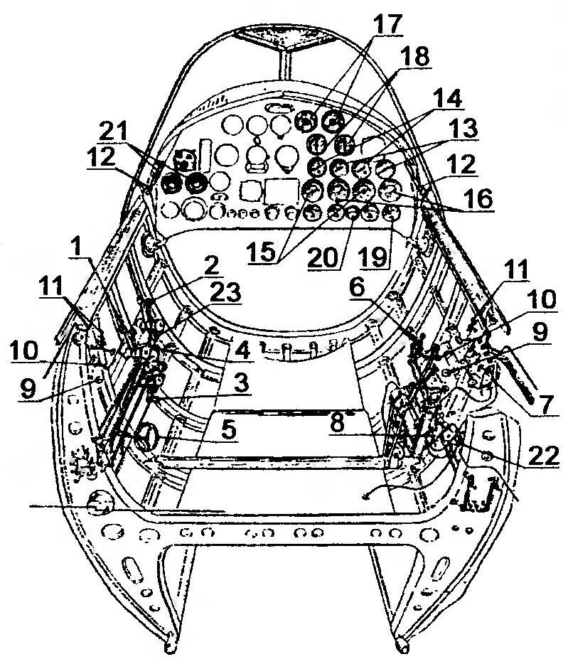
Control of the engines from the cockpit:
1 — the sector normal gas; 2 — gas sector altitude; 3 — sector fire specks; 4 — sector cable control by changing the pitch of the screws (on aircraft with VISH-2); 5 — control wheel covers cowl; 6 — a gear sector shutters; 7 — control panel start engine; 8 — manual-starter AKR-30; 9 — controlled oil injector; 10 — crane control emergency discharge of water; 11 — control manifold taps tanks; 12—valve; 13 — compensated pressure of gasoline; 14 — pressure-oil; 15 — electrothermometry oil; 16 — electrothermometry water; 17 — elektrotahometrs; 18 — manovacuummeter; 19— pointer benzinaio; 20 — the switch of benzenamine; 21 switches working magneto; 22 — drain the Park; 23 — scale sector altitude corrector
On the dashboard the pilot set the navigation instruments and apparatus motor equipment, electrical equipment and chassis.
The electrical installation of the aircraft is powered by a generator DSF-1000-powered drive motor and connected in parallel with the battery. In flight, when the engine speed is reduced to 1650 rpm and below, the supply of electricity is automatically switched to battery.
Communication with ground stations and between aircraft of the detachment is made using a special radio installation. Radio 13СК-3 (24-series bombers — ALS) located in the cab radio operator-gunner.
Crew communication between them is carried out using a three-color alarm, alarm and intercom SPU-3 and pneumopathy.
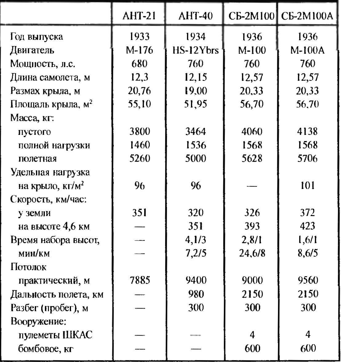
The basic flight characteristics of the prototypes and production aircraft SB
In case of a night landing, the plane secured parachute rockets, underwing torches and manual aircraft spotlight (RSP-150).
The armament of the aircraft consists of bombing and shooting. Bombs are in the bomb Bay, which occupies the Central part of the fuselage. Signalone the wing spars which pass through the bomb Bay, determined the scheme of placing bomb racks and suspension of bombs. Large-caliber bombs weighing 500 kg are suspended in the bomb Bay only horizontally under the wing spar, and the suspension of bombs of smaller weight — 250 kg and less, in combination: vertically in front of the bomb Bay between the wing spars and horizontally in the rear of the bomb Bay behind the rear spar of the wing. Management is dropping bombs from the cockpit of the Navigator using an electric or mechanical mechanism. In the cockpit there is a duplicate emergency derailer. The entire bomb load weighing 500-600 kg is placed near the center of gravity of the aircraft and his volley doesn’t have a significant impact on characteristics of stability and controllability of the aircraft.
Can be used this combination of bombs: 2×250 kg 2×250 + 4×25 kg, 6×100 kg, 4×100 + 2×25 kg, 6×70 + 4×10 kg 1×500 kg.
To repulse attacks of enemy aircraft the aircraft is equipped with three closed in flight gun emplacements. In the cockpit of the Navigator is the “spark” of the two movable ShKAS machine guns in the cabin arrow has two movable machine guns, each with one machine gun ShKAS. Ammunition “Sparky” consists of 1920 rounds. Feature defensive armament of the aircraft ANT-40 is that in cruising flight the machine guns in the cockpit of the arrow are removed polojenii in the fuselage and only when it detects enemy aircraft gunner opens the lantern of his car and removes from her top gun in position for firing. After the attack the turret rotates the gun barrel back (tail plane), and a machine gun fits into a special slot in the fuselage, is fixed in it and a canopy arrow closes together with the entire turret. The rise of the machine gun, mounted on turret arch, in the firing position and lowered into the fuselage are manufactured under its own weight arrow. A similar operation is carried out Lugovym a machine gun.
The aircraft belongs to a class of machines built with all the novelties of aviation technology, and is a very complex structure with a large number of individual complex mechanisms. Therefore it is necessary especially careful to follow all the mechanisms and glider plane to get good results with it.
N. Food reserve was, A. NECHIN, Kharkov
Recommend to read
 AFTER DRILL – needle files
Often, after the hole is drilled,further or a clean, slightly to expand or to make a slightly oval shape. This work can be facilitated steel Bender, automating it with a drill in a... BAG FOR NEWSPAPERS
Keep Newspapers and magazines in a pile is inconvenient. Make this table a shelf of two wooden stands and wooden cross rods, which pressurewe soft cloth (or leatherette) to the panel in...
