In 1951, the factory No. 168 was transferred to the production of Il-10, resulting in the task of gliders took off, and touched the rigging and ordered to transfer to Chkalov. There is the issue of the Yak-14 made in
1952 , after the construction of 152 copies. Thus, three enterprises in the amount of 417 built gliders (including prototypes).
The Yak-14 was armed regiments, which was based throughout the Soviet Union – from the Belarusian military district to the Maritime provinces. For example, it is known that they have existed in the 12th red banner military-transport division, 334 and 374-m military transport shelves. Commanders gliders were officers, graduates of the Pugachev gliding school, and co-pilots – sergeants-enlisted – graduates of the gliding school in Slavgorod or sergeants are conscripts that came from the flying clubs, which at that time was transformed into a flight school. The third crew member was a mechanic who followed the technical condition of the machine.
The crew participated in loading the glider. His role was to control the reliability of fastening of cargo in the cab and the determination of alignment. The load, such as a car or a gun, fixed for 10 to 15 minutes, and after landing were released for 3 – 5 min.
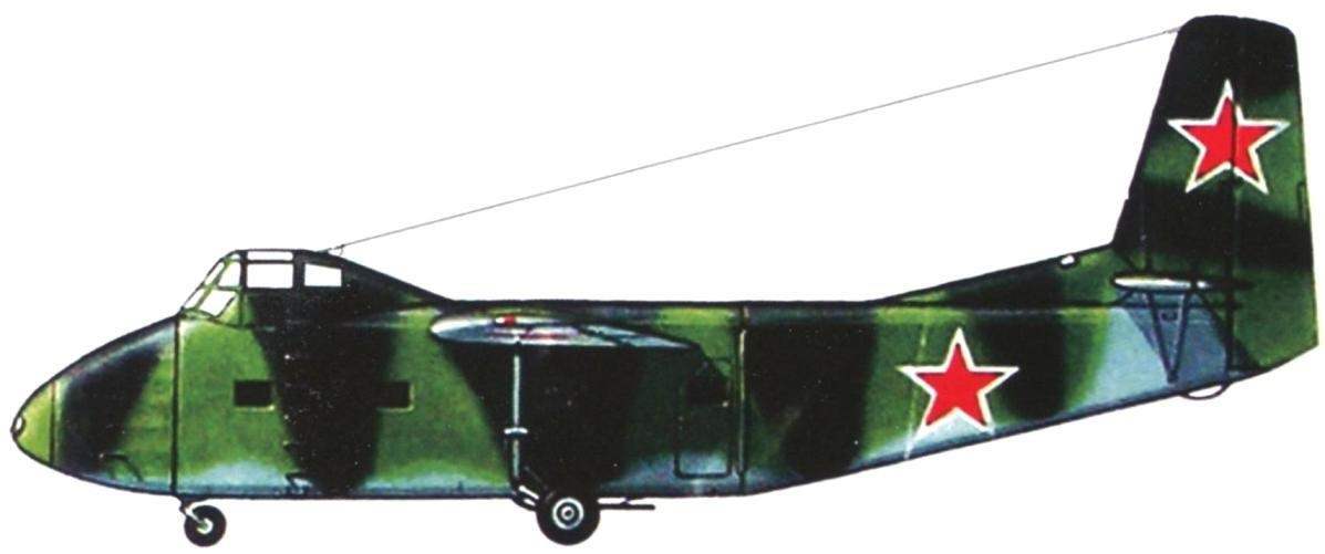
The prototype glider Yak-14. Note the lack of forces
Yak-14
Combat training: the truck GAZ-67B downloads the 57-mm gun in the airframe. The pilot took a seat in the cockpit. During the winter, and under the belly of the airframe visible long ski
The gliders were kept under the open sky. As a result, moisture penetrated inside the apparatus and accumulated in the nooks. Despite the many drainage holes, not all of it then he went outside. After a particularly heavy rainfall, the glider had to shake in order to detect the remaining water. Then the mechanic it was dredged, and the remainder was blotted with a rag.
The Yak-14 flying pilots previously mastered the glider C-25 and G-11. The latter, after debiting them from the military used as training. The difference is that the aerodynamic quality of the G-11 reached to 16 and the Yak-14 was equal to only 12.5, so at first it was possible to fly into the area for complex aerobatics and the second is not. In flight the Yak-14 was recalled, as expressed by pilots, “Gypsy horse”: close-fitting fabric between the attachment places swelled out, and sometimes bend inward, so that the frame was sticking out like ribs from a skinny horse.
As for the tactical qualities of the glider, their disadvantages due more to a lack of power towing. Still, the Il-12D (or T) with two engines AL-82FN was weak for a glider with a takeoff weight of 6750 lbs. For take-off coupling of the Il-12, Yak-14 was required pad length less than 1800 m and with an open approach. Narrow the range of permissible speeds and large turn radii causes the duration of the take-off linkage consisting of the squadron, and especially the -shelf. The result is a column of links aeroscape stretched for a great distance, which delayed the planting process. And that is the loss of surprise and tempo of the assault. The problem was exacerbated by the small range of Il-12. This limited the choice of airfields and landing sites. So massive use of the Yak-14 in major amphibious operations, promised to be very difficult.
Plaque glider pilots in the early 1950-ies ranged from 20 to 60 hours per year, depending on units: in Tula – more, and in Primorsky region -less.
Not complete without flight accidents. The story of one veteran, once after take-off climb tore the right emergency door of the cockpit. Engineer regiment, not believing that the door was secondlina, ordered the crew to find her, threatening that, otherwise, they themselves will produce. To find the door failed in the garden of one of the locals. Soon the door was hoisted into place, and she regularly stood until the end of operation of the airframe.
Was disaster. Over Vitebsk after uncoupling from a towing vehicle during a landing approach, the glider was not out of the roll, slid on the wing and crashed. The crew and Marines were killed. Officially the cause of the disaster is not established. But unofficially, the main version was the lack of training of the crew, which led to errors in piloting, resulting in loss of speed and stalling of the machine.
Another case occurred in Polotsk, during night flights. During takeoff aerosapce paratrooper, who was in the stern, grasped the handle of the lock, fixing the tail portion in the closed position. The handle was nezakonchennoy and aft fuselage, freed from holding her locks, slowly began to step aside. Soldiers tried to rectify the situation by grabbing hold of the fuselage and its tail part, but the strength is not enough… the Glider lost control and crashed.
The Yak-14 was not used in actual combat, and the most striking episode in their “biography” was the flight to the North pole. The Soviet Union tried to establish airfields in the Arctic ice to pose a threat to the United States. Naturally, it was necessary to deliver the goods for such airfields. Suggested to use cargo gliders. In 1950, the Soviet pilots were made polar flights in gliders C-25. In 1954 it was decided to repeat, but with a practical purpose – to deliver goods on the drifting station “North pole-4” (SP-4). Officially, it was scientific, and in fact the airfields for strategic bombers.
The training was led by generals N. With. Skripko and E. F. Loginov. Prepared four aerosapce from towing the Il-12D and gliders Yak-14. In the first coupling, the commander of the tow plane was A. N. Haritonin, and the crew of the glider consisted of M. S. Polukhin and
A. A. Alysheba. The second coupling of the Il-12D was flying G. I. Gladkov, and the Yak-14-Y. M. Gudilin and A. I. Leoshko. The third hitch the tug was piloted by N. And. Maksimov, the glider was B. F. Rodin and J. G. Tradedin. On the fourth coupling detailed data are not available, we only know that one of the members of the crew of the glider bore the name Kurmanayev.
During the training the crews often flew in, carrying on Board the glider artillery weight of 3.5 t. the Flights were carried out by day, night and adverse weather conditions. Worked out this unusual technique as landing without disengaging (both tug and glider), usually never did.
Before the flight the gliders loaded. In one placed the compressor and the explosives in the other – is equipped with a blower car GAZ-69. In other put other necessary goods. The towers were empty.
The flight began on the morning of March 10, 1954, Myasnovo airfield near Tula. After four hours, took place the first landing in Kazan. The next day flew to Sverdlovsk, and then to Omsk. Then along the TRANS-Siberian railway was the flight to Novosibirsk, and in the evening to Krasnoyarsk. The next day, after 3.5 hours of flying along the Yenisei river, was in the stony Tunguska river. The section from Podzemnoi Tunguska to Igarka was the hardest – hit in the afternoon. The pilots of one of aerosteon lost orientation and landed in taruhan-SK, where flew to Igarka, after the establishment of the good weather.
At the stage Igarka – Khatanga was in the icing. This was followed by flights to Cape Kosisty in the Laptev sea, two days in the Bay of Tiksi at the mouth of the Lena. The day reached the village of chokurdakh, refueled there, and the same day landed in Crosses Kolyma. March 26 from plentywood of aerosapce flew to Cape Schmidt, where the expedition remained until April 1. There on the glider Polukhina loaded the bulldozer. It had previously taken to Cape Schmidt disassembled four aircraft. Now he entered one of the Yak-14. However, it turned out great Overdrive, so part of the crawler tracks are lifted and moved to another glider. But in this case, the overload was equal to 700 kg. But the airframe survived. In other Yak-14 was loaded with a diesel generator, drilling machine, and the radar system of “blind landing”. Before departing I put a new tow ropes. After all the preparations, the expedition took off and headed for SP-4. After 4 hours 40 min. reached the ice airfield. The gliders unhooked, and the towers returned to the Wrangel island. The Yak-14 was successfully boarded, bringing the explorers needed goods. The entire expedition took 109 hours 21 mins flight time. Glider pilots returned to the mainland on other planes, and the gliders left on the ice. So was completed this outstanding flight. Any winning bidders not known.
Bow cook. Seen towing the castle in the centre, rosette of the aircraft intercom system and headlight
Generator GSK-1500 with a windmill mounted on the strut
The tail of the glider aside. On the left side see a door. On the right edge of the fuselage is a lock to secure the rear. The portholes are visible round the loopholes for ventilation and firing personal weapons of the troops
The Cockpit Of The Yak-14. In the center – instrument panel with navigation instruments. Below, the “beard” visible steering wheel trim rudder, again below the taps and gauges of the air system. Between the seats -steering wheel trim ailerons, near the left seat – the lever of a manual brake
Electro – and radio equipment, located behind the right seat pilot
Troop-carrying gliders was in service with the Soviet air force until the mid 1950s when they were replaced by turboprop transport aircraft an-8 and Mi-4 and Mi-6. As for glider pilots, those who are lucky retrained on the right of the pilots of the An-8, and people were not so lucky – ARTStrelka on the same plane. Some time part of the gliders was in conservation, but in a short time they went to be scrapped. To date there is no single Yak-14.
Gliders of this type were exported. In 1953, the Soviet Union handed over Czechoslovakia 10 gliders Yak-14 and TS-25, where they received designations, respectively, PC-14 and NK-25. The first two Yak-14 (PC-14) was taken in tow for Il-12 to the airfield Peshov in Eastern Slovakia.
After testing the gliders were transferred to the airfield Chleby near Prague. Until mid-1953 was the training of pilots, after which the gliders with the crew included in the Separate regiment of transport aircraft; they formed a 4-squadron. In Czechoslovakia, the first three PC 14 got individual Board numbers – D-43, D-44 and D-45.
In the spring of 1955, the Yak-14 was used in the exercise of the Czechoslovak army: they air-delivered the car “Tatra” with the gun and crew of six people. In September 1955, two glider participated in the aviation festival at Prague airport Ruzin, after which their pictures were in the press. In Czechoslovakia, as we do, the Yak-14 was operated until 1956, and then went for scrapping.
History of transport gliders -a component of the history of aviation. The greatest development they received during the great Patriotic war. Then the Soviet gliders were produced in large batches and used in a real combat situation. Although we did not conduct such a large-scale landing operations, the Germans or our allies, but the Soviet gliders, apparently, performed night sorties, more than all the glider pilots of other countries combined.
In the mid 50-ies of XX century era troop-carrying gliders over. In their place came a heavy transport aircraft and helicopters. Such advantages of gliders as quiet flight and a low cost of manufacture could not outweigh the shortcomings, such as the singleness of use and restrictions on the choice of the landing site compared to a newly created vehicles.
In the postwar years, and at us and abroad have been several attempts to revive the transport glider, but they all failed. And in our time for manned gliders remained a niche sport and entertainment, but it’s for the best…
A BRIEF TECHNICAL DESCRIPTION
Yak-14 had a classic aerodynamic design with the top wing. The latter was supported by the struts and controlcase. The main construction material – steel hromansilevyh pipe, sheet duralumin and fabric.
The fuselage had a rectangular cross-section and consisted of three parts: the front, middle and rear. The middle part was a cargo compartment with dimensions of 8000x2355x2250 mm. Shape of the fuselage is formed of spatial farm from hromansilevyh welded pipes. The lateral stiffness of the cargo compartment was provided by six frames, which is attached to the wing struts and landing gear. The top of the frame overlap with dural stringers, they were sewn and fabric glued the cording. The cargo compartment had two doors dimensions 1480×830 mm. On the left side the door was located in the tail, and on the right – nose. This arrangement ensures the ease of movement of personnel and good access to the cargo placed in the cab. Doors could be opened in flight to allow paratroopers if necessary, to leave the glider with a parachute. Each glider had a set of 12 mooring ropes with a large adjustable length.
The nose and tail of the fuselage, fastened by hinges, could lean to the side (nose -right, tail – left). This solution is provided through access to the cargo Bay, and in the case of damage to the bow during the crash -retrieval of cargo through the rear hatch. In the zygomatic parts of the nasal and middle compartments had dural covering, which ensure smooth transitions for attaching linen wraps. In the cargo Bay installed brackets for tying down cargo. Marines were placed on Board seats, partly on the cargo ramps (any of the gangways), which was attached to the special nodes. The estimated number of paratroopers -35 – 37.
The cockpit where the two pilots were in the front on the cargo Bay and was shifted to the left, for good visibility during landing. Access to it was carried out from the cargo Bay by using the stairs and outside, which on the left side there was a stage overlooking a stream. The front door can be reset in-flight under emergency evacuation of the glider. Strongly serving up the cockpit significantly increased midsection, which in turn reduced aerodynamic efficiency to 12.5. But this solution provided ease of loading and unloading operations and the safety of the crew in collisions with ground obstacles.
The wing in plan had a rectangular middle part and a trapezoidal console. Elongation was small and 7.8, which also reduces air quality. Each console is attached to the fuselage at two points and supported by the strut and controlroom. Wing profile – Сlаrk-UN with a relative thickness of 15% in the middle part, which was reduced to 8% at the wingtips. The wing had a single spar and a rear wall. Spar (like the frame of the fuselage), has been welded from steel tubes, the wall of skladyvalas of duralumin angles and sheets. The cross consisted of 32 of the rib truss, riveted duralumin profiles. Further along the scale was put dural stringers. From the leading edge to the spar, the wing had a metal casing thickness of the root portion of 1.8 mm, which gradually decreased to 0.8 mm at the tip. On the rear wing was mounted slotted flaps (two sections) and Aileron (two sections). The ailerons and flaps had duralumin frame and fabric covers. On the inner section of the left Aileron was mounted trimmer. On the upper surface of a wing mounted vane spoilers.
Empennage classical scheme of single-fin. The stabilizer consisted of two parts, which are mounted in the lower part of the keel. The stiffness of a stabilizer provided two pairs of ribbon braces, fixed on the fin and fuselage. The plane of the stabilizer and rudders have a similar structure consisting of a duralumin frame and fabric covering. The rudders were fitted with trimmers.
Landing gear consisted of a tricycle landing gear with nose wheel and landing skis. The main landing gear had a single brake wheel size 900×300 mm. bow front – swiveling single wheel size 600×250 mm. All racks supplied with oil-air shock absorbers. On the bottom of the fuselage near the main landing mounts were placed two landing skids with rubber plate damping. Ski – layered, laminated of wood of different breeds. On the tail of the fuselage below was a metal protective arc. In the case of landing on skis the air out of the shocks produced, the wheels were raised, and the runners of skis came in contact with the ground. So did to reduce the floor height above the ground when loading. Interestingly, when you open the valve and release the air first shortened the right front, then the front and finally the left. So, rocking, glider “squatted” on 450 mm. After loading the air from onboard cylinders again run into the shocks, and the Yak-14 was slightly above the ground. Sometimes the air pressure is not enough. In this case, a dozen people were taken for the struts and frame of the glider and began to rock while pulling up. As a rule, then the unit normal on chassis. Controlled shock absorbers was carried out from the cockpit with the help of cranes. Brakes are also operated by compressed air.
TECHNICAL DATA of the YAK-14 AND GERMAN GLIDER Go 242A-1
Control of the glider – double, consisting of a wheel and pedals. Control wiring – soft, cable. All handlebars had the trimmers. Release and cleaning flaps – on-Board air system, and the management of spoilers – mechanical, cable.
In the equipment of the airframe consisted of air and electrical systems and flight-navigation complex, which included the most necessary instrument: the pointer of the roll and slide (on some gliders it was replaced by a standard artificial horizon), altimeter, air speed indicator, variometer, clock and magnetic compass KI-11. Some of the gliders were equipped with radar system “Strizh”, which allowed to determine the position of the tug in conditions of poor visibility.
Aircraft intercom SPU-5 gave the opportunity to the crew of the glider to talk to the commander of the troopers in the cargo cabin and with the crew of the tow plane. In the latter case, the negotiations were conducted through the wire laid along the tow rope. The glider was equipped with a radio RSI-6K, which has provided communication within a radius of 140 – 150 km at an altitude of 1000 m.
Electrical system of the glider consisted of a battery 12-A-30 and the electric generator GSK-1500 driven by a windmill with variable pitch. The latter provided a stable operation of the generator over the entire range of speeds. Electricity powered communication equipment, lighting pilot and cargo cabins, navigation lights and landing light FS-240.
Air system had two spherical balloon with a capacity for 22 L. using compressed air produced release and cleaning flaps, pressurization of the dampers landing gear and brakes-all wheels.
Bibliography and sources
Grzybowska K. V. the development of the transport gliding. – Moscow, Mashinostroenie, 1993. Kazakov V. B. To the Arctic for non-motorised. – M., 1999.
Krasil’shchikov, A. P., Gliders Russia. – M., “Polygon-press”, 2005.
Krolikewicz T. Szybowce transportowe, Warszawa, 1985.
Murawski E. Samoloty Luftwaffe, t.2, Warszawa, 1985.
Magazines: “Aviary”, “Wings”, “Wings of Motherland”, “world Aircraft”, Flight
Recommend to read Milling cutter instead of a plow The tiller developed by Heinrich Alekseevich Kuznetsov differs from many homemade designs by using cutters instead of a plow. Rotating on the working shaft, they simultaneously till the... WITH POLYGON — IN THE MUSEUM Heavy duty anti-tank gun BOB-25. The famous "sorokopyatki" — 45 mm 19K anti-tank gun of the sample in 1932 and its upgraded version 53K model 1937 was in fact the only anti-tank guns by... 
 Taking into account the experience of glider landing operations of the allies during the Second world war, the Soviet government also decided to provide for their airborne troops in large gliders capable of carrying heavy weapons. The decision was taken in 1947 By this time, the team of V. K. Gribovsky was already disbanded and specifications for the design of heavy gliders got the design Bureau of A. S. Yakovlev and S. Ilyushin.