
 The Grumman F6F HELLCAT. Analysis of the results of air combat in South-East Asia with the participation of the new Japanese high-speed fighters allowed American experts to draw a conclusion about necessity of creation in the US carrier-based fighters with higher performance. Orders to create prototypes were issued to multiple firms.
At the end of June 1941 the order received and firm Grumman: she was instructed to modernize its fighter F4F WILDCAT. It was assumed the construction of two prototypes under the new 14-cylinder radial engine Wright R-2600 CYCLONE takeoff power HP 1622 the First of the prototypes XF6F-1 was supposed to equip with engines R-2600-10, and the second XF6F-2 — improved version with a turbo R-2600-15.
When creating a new aircraft design team of the company under the leadership of L .The Grumman and W. Swindler made to the layout F4F many changes and new technical solutions.
Thus, the weight of the fighter has increased 60 percent compared to the F4F, which forced designers with the aim of preserving maneuvering characteristics to increase the wing area. The car received the fuel tanks of greater capacity and enhanced service. The cockpit was raised and is positioned over the fuselage fuel tanks, which improved the overview of the front hemisphere.
Fly the first prototype XF6F-1 was performed on June 26, 1942 S. converse, the participant of fights on the Midway. In his report he pointed out the need to install a new engine Pratt and Whitney R-2800 power 2028 HP instead of the Wright R-2600 CYCLONE. Engine R-2800 has passed successful tests on the first copies of the Corsair fighters, and it was installed on the prototype of the XF6F-3, test flown on 30 July 1942. The first flights showed that the aircraft as a whole was a success, and it launched into serial production.
The construction of the second prototype XF6F-2 was delayed, and its first flight took place only on 7 January 1944. One of the two prototypes XF6F-1 with the engine R-2800-27 and four 20 mm guns, designated XF6F-4, was test flown on 3 October 1942.
Immediately after the start of serial production of aircraft F6F-5 two of them were equipped with four-bladed propellers and engines Pratt and Whitney R-2800-18W takeoff power 2129 L. S. the First of these experimental machines — XF6F-6 — flew on 6 July 1944. The fighter showed the highest rate of all the prototypes and production F6F—671 km/h at a height of 6710 m. the Second instance flew on 30 August 1944.
After comparative tests it was decided to start serial production of the XF6F-3, fully met the requirements of the customer. The contract for serial production of the aircraft, the designation HELLCAT, was signed with the firm even before the start of flight testing — may 23, 1942.
Preparation for serial production was deployed in long island in August 1942. Installation of the ramps began in October and, without waiting for completion of the work, started assembling planes HELLCAT.
The first production F6F-3 was collected at the operating enterprise of the company Grumman in Bethpage. In parallel with the serial production were conducted and army trials. In one of such flights have the first production F6F-3 HELLCAT in developing aircraft carrier landing broken landing hook. This accident forced the engineers to strengthen the attachment of the hook, and then having trouble with it never happen again.
In the production process in the design of the aircraft was continuously altered. Thus, the antenna of the radio installed without tilting, the barrels of the guns closed profiled fairings, removed the bottom fold of the cooling channel of the engine.
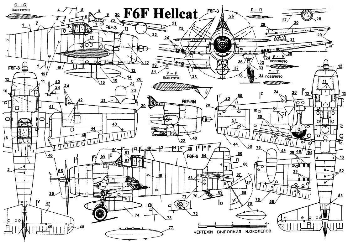
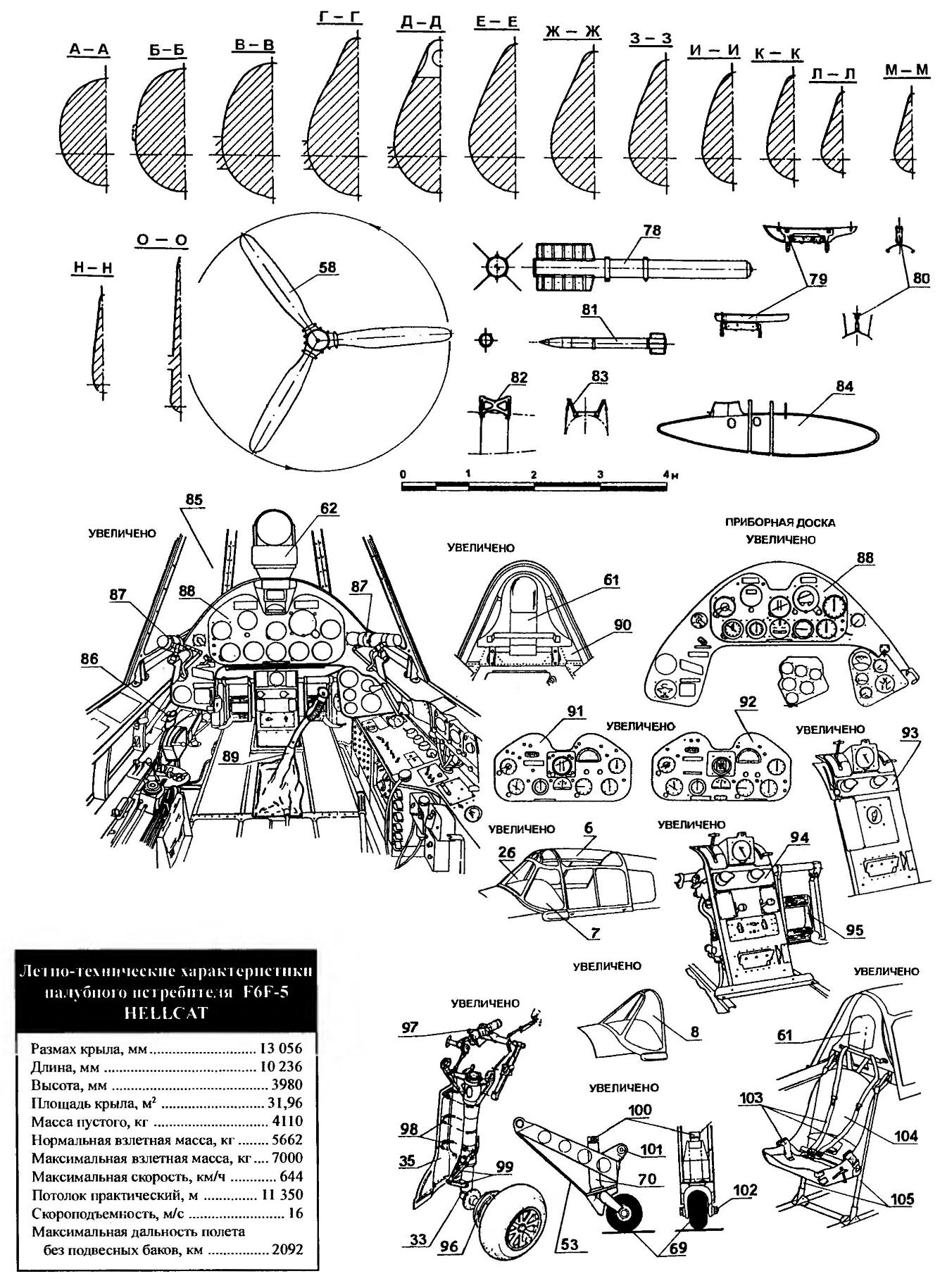
Carrier-based fighter F6F HELLCAT:
1 — pin radio antennas; 2 — indicators of recognition; 3 — antenna (in the early series F6F-3); 4 — antenna; 5 — the radio antenna mast (late production F6F-3); 6 — movable part of the lamp; 7 — canopy canopy (early series F6F-3); 8 — canopy canopy (late production F6F-3); 9 — cover observation of the neck of the oil tank; 10 — panel access to the engine; 11 — adjustable louvers cooling of the engine; 12 operating panel of the engine hood; 13 — output channels of the exhaust gas; is 14.37 — external fuel tank with a capacity of 568 l; 15 — emphasis of the fuel tank; 16 — tie fuel tank strap; 17 — hatches fillers fuselage fuel tanks; 18 — operating hatch power station; 19 — footrests; 20 — ANO; 21 — a fragment of right-wing F6F-3N; 22 — fairings PJIC; 23 — LDPE; 24 — 12.7 mm machine guns; 25 — position of the folded wing; 26 — frontal armoured glass; 27 — left wing tip of the wing F6F-5N; 28 — spotlight (some planes F6F-5N); 29 — chinafotopress; 30 — left wing tip of the wing F6F-5; 31,81 — unmanaged 127-mm rockets; 32 — line of folding wing; 33 — main landing gear; 34 — wheel main landing; 35 — plate of the main stand; 36 — plate node of cleaning of the main landing gear; 38 — right console wing F6F-5; 39 — a guide 127-mm NUR; 40 — 20-mm cannon; 41 — propeller unit rotation of the wing; 42 — access doors ammunition boxes; 43,52 — front lights; 44 — Aileron; 45 — flap wing; 46 — the flap of a wing center section; 47 — stabilizer; 48 — steering wheel height; 49 — trimmer of the Elevator; 50 maintenance access doors of the wing; 51 —window pillsoverseas; 53 — plate tail-wheel; 54 — the hinge of the flap of the center section; 55 the hinge of the flap console; 56 — trim of the ailerons; 57 — hinge Aileron; 58 — a three-bladed propeller; 59 — hatch refueling water tank; 60 — rear view mirror; 61 — the headrest of the seat: 62 — sight; 63 maintenance access doors control system; 64 Kil; 65 — rudder; 66 trimmer rudder; 67 — marker light; 68 — off and landing a hook; 69 — the tail wheel; 70 — strut tail wheel; 71 end — to-end pipe node lifting of the rear fuselage; a 72 — setting the camera to the F6F-5P; 73 — onboard camera on the F6F-3P; 74,84 — variants of PTB with a capacity of 568 l; 75 — adjustable trimmer right Aileron; 76 — outboard fuel tank capacity 330 l; 77 — external fuel tank with a capacity of 567 l; 78 — unmanaged 298-mm rocket; of 79.80 — options for the underwing pylons; 82,83 — options under-fuselage holders; 85 — cockpit F6F-3; 86 — ORES; 87 — lamp lighting of the dashboard; 88 — dashboard; 89 — handle: 90 — back; 91 — the Central panel of the dashboard, the F6F-5; 92 — the Central panel of the dashboard, the F6F-3N; 93 — Central control panel weapons F6F-5; 94 Central control panel weapons F6F-3; 95 — foot control rudder; 96 — brake drum-wheel main landing gear; 97 — cylinder retract main landing gear; 98 — clamps fastening flap main landing gear; 99 — dvuhsvetny main landing gear; 100 — the axis of the shock absorber to the front of the tail wheel; the 101 —unit rotation of the tail landing gear, 102 — axle tail wheel; 103 — the harness system of the pilot; 104 — pilot’s seat; 105 — mounts chairs
From January to April of 1944 all serial F6F-3 HELLCAT was equipped with uprated Pratt and Whitney R-2800-10W with water injection system that allowed short-term increase engine thrust to 2231 HP Edition F6F-3 concluded on 21 April 1944, after the release of 4401 serial instance.
In early 1941, work began on the creation of radar stations (RLS) for single-seat fighters. The most successful radar AN/APS-6 was developed at the Massachusetts Institute of technology. As shown by calculations of the aerodynamicists, the installation of such radar “eat” up to 32 km/hour speed of the aircraft. But the range of detection of air targets increased up to 7.2—8 km.
Trial installation of the radar AN/APS-6 on the XF6F-3N was completed in July 1943. After completion of the test aircraft under the designation of the F6F-3N was launched into serial production. All night fighter HELLCAT was additionally equipped with a radio altimeter AN/APN-1, system of identification “friend or foe” AN/APX-1 and the landing spotlight. In all there were 205 instances of the F6F-3N.
The night fighter variant of the F6F-3E, issued in the amount of 18 units, equipped with radar AN/APS-4, which had a wider search range in azimuth, but shorter range. The antenna for such a radar was placed in the container is a teardrop shape and hung under the right wing.
Reconnaissance modification of F6F-3P was designed for photo-reconnaissance from high altitudes. The camera gave the ability to perform panorama shooting in horizontal flight while maintaining a fixed altitude and airspeed.
The first production instance of the aircraft F6F-5 flew on 4 April 1944. On a new modification of the fighter HELLCAT mounted engines R-2800-10W. Was strengthened book — lots of additional armor plates has reached 110 kg. in addition, further reinforced the aft fuselage, under the wing set the standard bomb racks and rails for rockets. Some of the later series aircraft wing, in place of the internal machine guns were two 20-mm cannon. From June 1944, all production copies could be installed gondola with the radar on the right wing and the Central panel of the dashboard screen display of radar data.
Production of the F6F-5 was discontinued in November 1945, thus completing the story of serial production of the aircraft HELLCAT. All collected instances 7870 F6F-5.
The total number of issued F6F-5 1529 copies accounted for the modification of the F6F-5N (including F6F-5E). Night F6F-5N was equipped with radar AN/APS-6 antenna on the right wing.
Aircraft F6F-5E was a night fighter variant with radar AN/APS-4 placed in the container under the right wing.
In turn, the F6F-5P was a standard F6F-5 equipped with camera to conduct photo-reconnaissance. Some F6F-5P had no machine gun armament was removed to increase the ceiling of the flight.
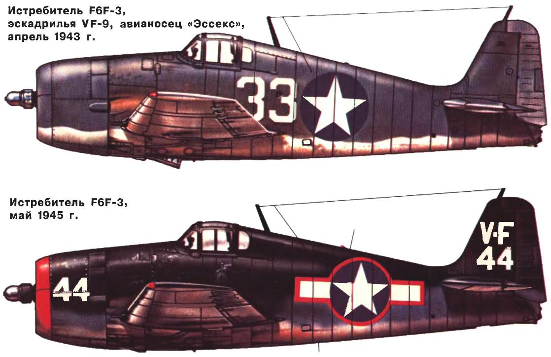
The first Department that received 16 January 1943 into service F6F-3 HELLCAT, the squadron became VF-9, based on the aircraft carrier “Essex”. New aircraft on 31 August for the first time took part in the fighting around the Islands, Marcus. The first of September near the island backer pilots F6F-3 from the structure of VF-24 from the aircraft carrier “Linen wood” and VF-23 USS Princeton was hit by three Japanese four-engine flying boat Kawanishi Н8К.
A great victory aircraft pilots HELLCAT won while performing the attack on the enemy fleet in the area Kwajalein and airfield on the island Roy on 4 December 1943. On this day a group of HELLCAT in part 91 aircraft destroyed 28 of 50 Japanese Zero, rising to meet them. Their losses amounted to only three machines. By the end of 1943, the HELLCAT became the main us carrier fighter of ports in the Pacific.
Combat check night fighter F6F-3N was held in February 1944. One of the F6F-3N squadron VF(N)-76 from the aircraft carrier “Yorktown” was hit by Japanese bomber Nakajima B5NI, carrying out the attack on the aircraft carrier “Intrepid”.
Aircraft modifications F6F-5 and F6F-5N started to arrive in combat units in the late summer of 1944. From February 1945, the HELLCAT fighters were in service with four squadrons of aircraft of the U.S. marine corps, stationed on escort aircraft carriers.
His last air combat in world war II HELLCAT fighter held on August 15, 1945. On this day, six planes of the squadron VF-88 from the aircraft carrier “Yorktown” intercepted nine enemy, losing four of their own.
In the war machines F6F was armed with 69 fighter squadrons (ten of them a night), seven squadrons of fighter-bombers and six Marines. On battle account carrier-based F6F — 4947 shot down in aerial combat enemy aircraft. Another 209 enemy machines shot down a HELLCAT fighters land-based. It was built 12 275 F6F aircraft of various modifications.
During the war in Korea, the unmanned F6F-5K with a suspended beneath the fuselage 908-kg bombs were used to attack targets, which had an effective air defense system. In August 1952 F6F-5K destroyed several railroad bridges in the area Chungnam. In flight, they were driven aboard carrier-based Skyraider attack aircraft.
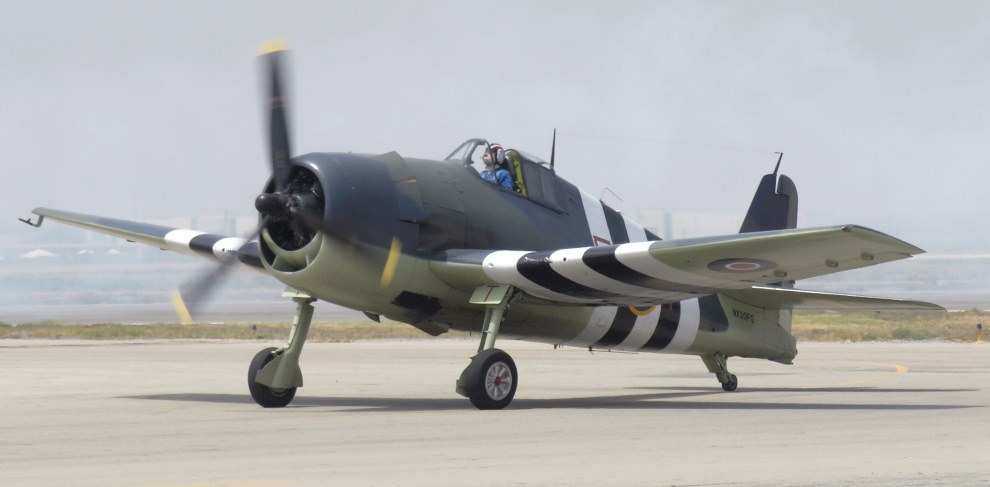
CARRIER-BASED FIGHTER F6F HELLCAT
It was a single-seat, single-engine low with retractable landing gear designed for carrier operations.
The fuselage of the aircraft aluminum, semi-monocoque, oval in cross-section shape. The fuselage was molded out of smooth leaves, was connected to a power set with rivets. In front of the dashboard and pilot seat were installed armor plate.
The wing is all-metal, trapezoidal shape. His force consisted of two main and one rear spars and ribs. Dural spars, stamped. Cladding made from sheet duralumin.
The wing had a center section and two consoles, which evolved along the fuselage. The ailerons are trimmed with canvas. Trimmer left Aileron could deflect a pilot, trimmer right drive had. Flaps were divided into four sections: two on the center and one on the left and right consoles. The power range of the flaps consisted of ribs and stringers. Trim — dural. All sections were simultaneously issued and retracted by hydraulic cylinders. This was controlled electrically or manually. Automatic release of the flaps occurred at speeds less than 315 km/h and cleaning in excess of this speed.
Tail unit all-metal construction. The power range of the keel — two spar and seven ribs. Trim — dural. The rudder, built from duralumin ribs and stringers and covered with canvas, was equipped with a trimmer. Stabilizer dural structures consisting of two halves, had a symmetrical profile and has been mounted under an angle of +4.5 degrees to the axis of rotation of the propeller plane. The design of each blade of the stabilizer 14 include ribs and stringers. Trim — dural. Elevators going from 13 ribs and stringers and trimmed with canvas. The elevators were located-driven trimmers.
Glazing of the cockpit is a fixed hood with front armoured glass and the movable part of the lamp made of Plexiglas. Open the lantern, moving back, during the rotation of the pilot lever on the starboard side of the cabin. There was also an emergency reset of the lamp. The cockpit glazing is supplied with de-icing system, which includes an alcohol reservoir and a cylinder of compressed air. System management manual. The dashboard consisted of a Central and two side panels. Located on the Central flight and navigational instruments and control devices operating parameters of the engine.
CARRIER-BASED FIGHTER GRUMMAN F6F HELLCAT
Control system — with classic handle and pedals. On the handle was located the trigger of the machine guns, dropping bombs and launching missiles. The plane was equipped with autopilot GR-1.
The power plant consisted of 18-cylinder air-cooled engine Pratt and Whitney R-2800-10W starting capacity of 2028 HP engine Axle was rejected down from the axis of the aircraft three degrees. Motor mount was attached to the armored power frames. Before the frame was located PROTEK-based oil tank. The engine has closed dural quick release hood. At the top of the hood was a sash to adjust the cooling of the engine.
The fuel system includes two main fuel tank for 331 l in the center section and the reserve tank capacity 284 l under the cockpit. In addition, under the fuselage could be suspended a fuel tank capacity of 568 L. also on wing pylons could fix two tank for 379 L.
The oil system consisted of a tank with a capacity of 79.5 liters, pump, two return pumps, oil cooler and electric control system oil temperature.
Radio TR1196 or SCR522A working in the ranges of short and ultrashort waves, installed in the radio compartment behind the cockpit.
Takeoff and landing gear is a tricycle landing gear with a tail wheel and landing GAK. Cleaning and release of the main landing was carried out by hydraulic cylinders. Alarm system of the landing gear is pneumatic. Depreciation racks oil.
Brake main wheel — hydraulic. Cleaning and release of the brake hook — hydraulically.
The primary armament of the aircraft to six wing-mounted 12.7-mm machine guns with ammunition 200 rounds each. When installed in the wing, two 20mm cannons, the ammunition was 250 rounds per gun. To report attacks on the left wing was mounted shot-method. Under each wing console, if necessary, installed launcher guides for NUR caliber 127 mm or 298 mm. in addition, the plane could take up to three bombs of 454 kg each.
N. Food reserve was, A. CHECHIN, Kharkov
Recommend to read
 PLASTIC GREENHOUSE
Living in Siberia, without a greenhouse on the site not to do — the summer is short and not always warm, and vegetables home you want. Therefore, sooner or later, every owner of even a... LUCKY THE DRAGONFLY
The first USSR championship flying micro models. It was held in 1990 at the Palace of sports "Dynamo" (room category III, altitude up to 30 m), but due to the lack of advertising and...
