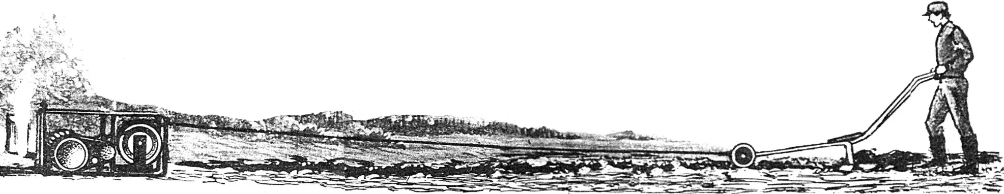
A winch working in tandem with a plow is nothing new. Especially for owners of small land plots, where these rather simple and reliable constructions have already proven themselves excellently.
Unlike a mini-tractor, the winch does not compact the soil. And it doesn’t slip like a motor cultivator. Practically all the engine’s traction power here is directed toward useful work — plowing the fertile soil with a towed plow. The winch itself is securely anchored in place by a ground anchor, whose blades, shaped like spade tips, easily penetrate the ground.
Plowing is done by two people, laying furrow after furrow. And the helper — who needs to return the plow to the beginning of the furrow — can even be a 10-year-old child. High-quality plowing is guaranteed even on difficult terrain (such as hills with a “washboard” profile) and heavy soils.
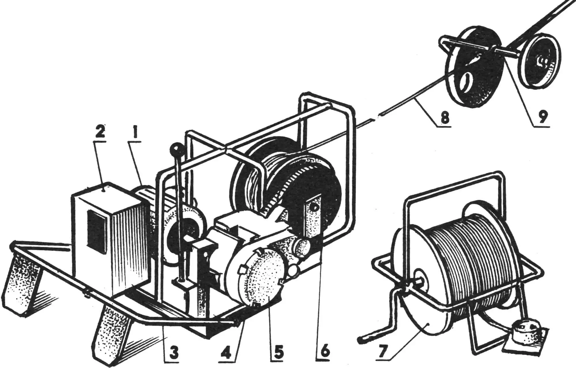
1 — electric motor with a sleeve coupling on the shaft, 2 — electrical equipment block, 3 — anchor, 4 — frame, 5 — gearbox, 6 — rope drum, 7 — power cable with storage reel, 8 — nylon rope, 9 — front part of the towed plow.
The proposed homemade electric winch-plow (see illustration) offers a number of additional advantages: the relative affordability of electricity, ease of acquisition, the long service life (over 30 years) of the electric motor, and the simplicity of starting and operating the whole system. The gearbox shift lever is located right next to the electrical equipment unit (capacitors, magnetic starter, “Start” and “Stop” buttons). Nearby is a coiled cable on a reel. This allows the electric winch to be anchored anywhere on the land plot up to 100 meters from the power source (beyond that, cable losses increase). A remote control panel with a “Stop” button allows one to operate it even in tandem with a disabled person.
If a boulder or tree roots get under the plow, the tension on the rope suddenly spikes. When it reaches the maximum permissible level (330 kgf), the winch motor automatically stops to prevent the rope from snapping (and to avoid damaging the chain drive mechanism).
One more feature. Thanks to its modular design, the winch can be easily disassembled: the motor and electrical block can be removed (just unscrew four M10 bolts) and installed onto a circular saw for preparing firewood, rails, timber, etc. Reinstalling these same modules onto a fodder shredder gives you a valuable, vitamin-rich feed for livestock and poultry. Swapping the plow for a towed hiller-cultivator turns the winch into a multifunctional tool for weeding, hilling, inter-row cultivation — or even digging potatoes.
Kinematics? The homemade unit is so mechanically simple (and therefore reliable) that it likely won’t cause any trouble when being built from metal. The motor shaft transmits rotation (via the sleeve coupling) to the gearbox (borrowed from a “Riga” moped with slight modifications). From there, using a 12.7 mm pitch chain drive, it turns the drum, which winds up a 10 mm nylon rope connected to a towed plow or hiller-cultivator (which also acts as a potato digger).
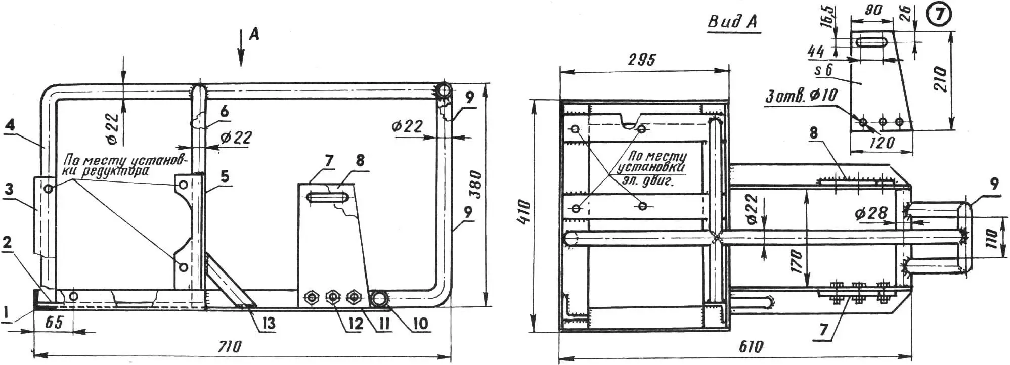
1 — welded subframe (made from 34×50 mm steel angle), 2 — electric motor bracket (5×50 mm steel strip, 2 pcs), 3 — left gearbox bracket (34×50 mm steel angle), 4 — top frame rail (22×3 mm water-gas pipe), 5 — right gearbox bracket (34×50 mm steel angle), 6 — arc-shaped welded bracket (22×3 pipe), 7 — removable drum bracket (6 mm steel plate), 8 — drum bracket (6 mm steel plate), 9 — rope guide (22×3 pipe, welded after drum installation), 10 — crossmember (22×3 pipe), 11 — lower frame rail (34×50 mm steel angle, 2 pcs), 12 — M10 bolt with nut (3 pcs), 13 — diagonal brace (22×3 pipe).
The frame is a welded assembly of 34×50 mm steel angle sections with tubular rails and brackets for mounting the electric motor, gearbox, and drum. The rope guide is made from a bent piece of 22×3 mm steel water-gas pipe and welded after the drum is mounted. The drum brackets are machined to fit the shaft, which can be moved slightly to adjust tension on the PR-12.7 roller chain.
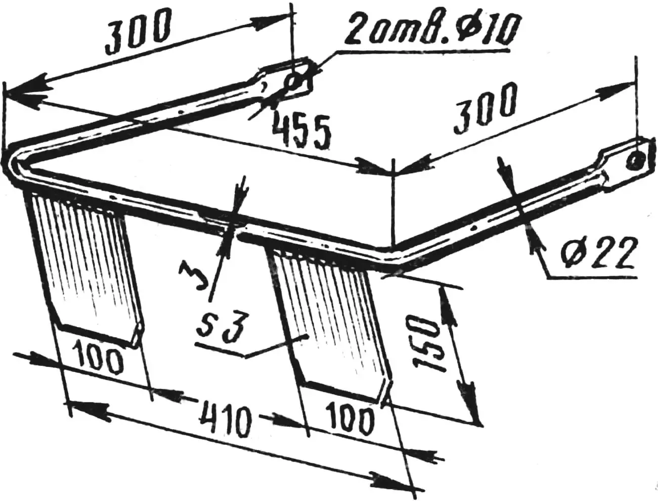
The anchor is also a welded construction (see drawing). Holes with Ø10 mm allow it to be attached to the winch frame (with the possibility of rotating on bolt-axes). The anchor’s “blades” are sharpened so they can be pressed into the soil by alternating foot pressure, just like spade blades, securely fixing the winch in place.
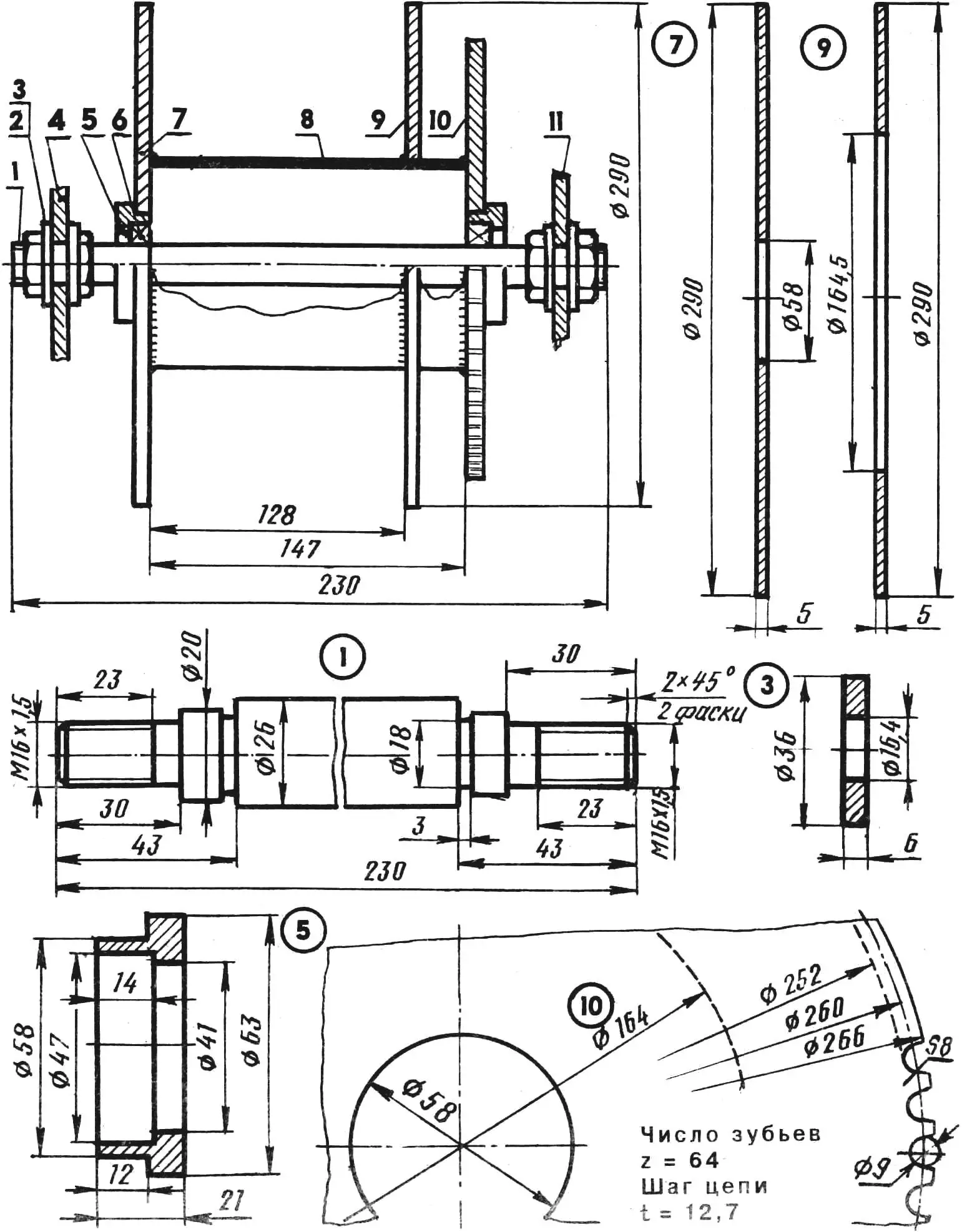
1 — shaft (St3), 2 — M16 nut (4 pcs), 3 — washer (St3, 4 pcs), 4 — drum bracket, 5 — bearing housing (St3, 2 pcs), 6 — radial ball bearing (80204, 2 pcs), 7 — left flange (St3), 8 — drum body (147 mm section of 164×5 water-gas pipe), 9 — right flange (St3), 10 — sprocket z = 64(66) (St3), 11 — removable drum bracket.
The drum is also welded. For mounting it on the shaft, use bearings with protective washers or seals (type 80204 or 180204). The bearing housings are homemade, turned from steel (St3). A sprocket (z=64, t=12.7) is welded to the right side of the drum. Alternatively, a 66-tooth sprocket can be used — it’s easier to machine on a lathe with a three-jaw chuck.
The towed plow is similar in design to the one published in issue No. 6 of 1990. Steel rods (16 mm diameter) are welded at stress concentration points. Unlike a self-propelled plow, this version features two handles made from 22×3 mm water-gas steel pipes, like the plow shank. The plowshare-moldboard is a single curved surface cut from the steel casing of a gas cylinder. This eliminates the need for a special hard alloy insert. An experimentally determined 6° attack angle significantly improved the plow’s performance.
As furrow and field wheels, of course, not only ready-made ones — taken, for example, from decommissioned agricultural machinery — can be used, but also homemade ones. The former are welded from 5-mm sheet steel, and the latter from 1.5-mm thick St3 sheet. They will not significantly increase the weight of the plow. And the final weight is unlikely to exceed 16 kg.
As previously noted, the electric motor is connected to the gearbox via a coupling that allows misalignment of up to three degrees. An M8 bolt is used as the pin, inserted into a hole drilled in both the coupling and the gearbox shaft. A nut is screwed onto the bolt and then locked in place like a castellated nut.
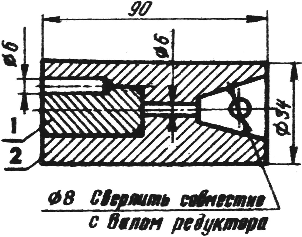
1 — auxiliary plug (St3), 2 — workpiece for the coupling (St3); after drilling a Ø 6 mm hole, the plug is removed, and the resulting semicircular groove is filed with a square file to fit the key.
If there is no slotting machine available, a keyway groove in the coupling for the motor shaft can be made using… a 6 mm drill bit and an auxiliary metal plug. The plug is then removed, and the resulting groove is finished to the required shape with a square file.
As for the gearbox from the “Riga” moped, it needs modification before being installed in the electric winch setup, with all non-torque-transmitting parts removed. For instance, the kickstarter is eliminated, and the hole is sealed with a rubber or aluminum press-fit plug. The clutch coupling’s driving and driven disks are welded together. Any extra clutch disks are discarded. On the gear block, the second gear’s teeth are completely removed. This significantly simplifies control. Only “0” and “I” remain on the gear shift lever.
Instead of the original crankshaft, it’s better to machine a new shaft. However, you can use the existing one, due to the difficulty of machining splines for the clutch coupling disk in a home workshop. In that case, the original crankshaft must be carefully balanced. How?
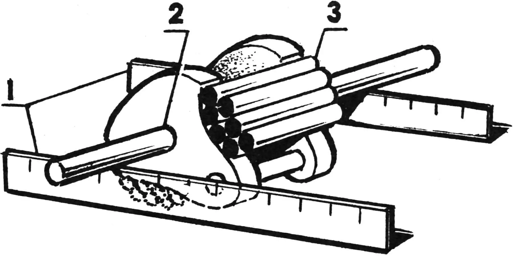
1 — horizontal guides, 2 — crankshaft, 3 — welded balancing weight (cut pieces of 8 mm steel wire).
After cutting off the connecting rod, a balancing weight — made from 8 mm steel wire scraps — is welded next to the shaft. Then, by removing excess material with a grinding wheel, a neutral balance is achieved with the crankshaft placed on perfectly horizontal guides.
The crankshaft is laid on the guides at the bearing contact points. This is done carefully to achieve accurate static balancing. Dynamic balancing is done “by eye.” The goal is to symmetrically remove excess mass around the bearing supports to minimize bending forces during rotation.
In practice, after such mostly static balancing, no vibrations are observed during operation of the gearbox — or the electric winch as a whole. However, this does not rule out the use of a different gearbox, especially a high-speed one with a worm gear in an aluminum housing. But how many DIYers can actually source one of those? Isn’t it simpler to just use an old, “junk” gearbox from a worn-out “Riga” moped?
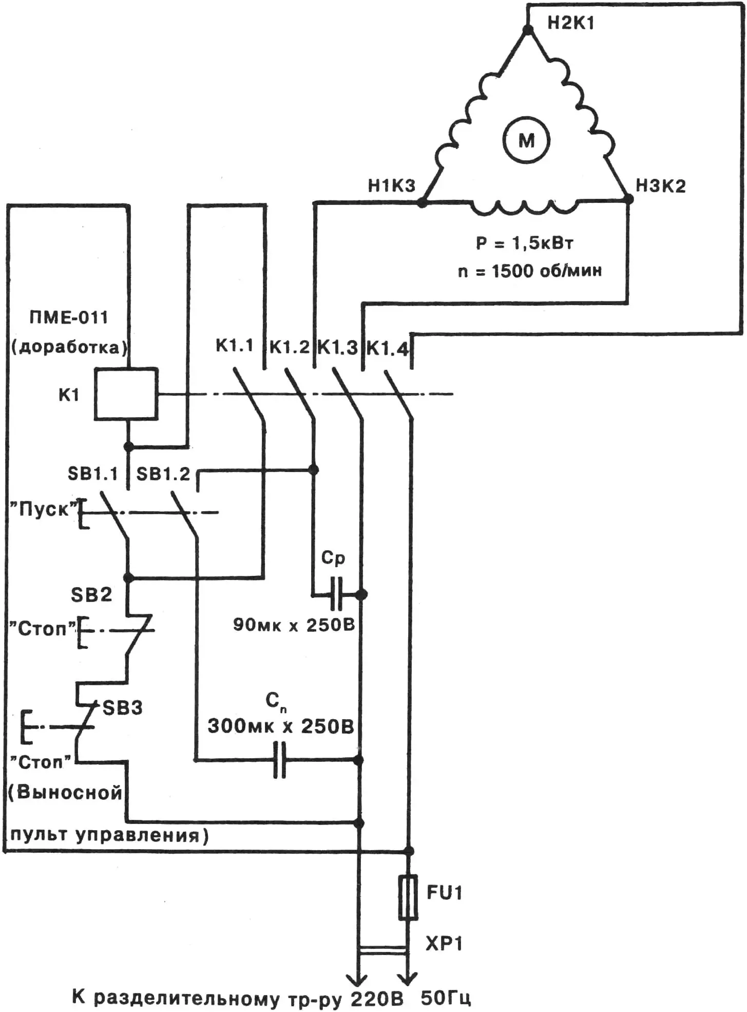
Connecting a three-phase electric motor to a single-phase power supply is usually not a big challenge for DIYers. In our case, a standard “delta” connection is used with phase-shifting capacitors. The capacitance Cr, in microfarads, should be about 60 times the motor’s power in kilowatts. The starting capacitor value is calculated as three times the working capacitor, i.e., Cs = 3Cr = 3×90 µF = 300 µF. The necessary capacitance is achieved by connecting (in parallel) available capacitors — for instance, type MBGK-1 — into a bank.
It’s also recommended to use a compact electromagnetic starter like the PME-011. But its coil is usually rated for 380 V, while we have 220 V. Therefore, some of the windings need to be removed.
For example, if the starter coil was originally wound with 9000 turns for 380 V operation, it should be reduced to 9000 ÷ 380 × 220 = 5200 turns for 220 V use.
A small modification is also required for the “Start” button. The second contact (usually normally closed in the factory version of the starter) needs to be reconfigured to normally open. This is fairly easy to do, thanks to the design of the switch.
One more thing. The control panel or at least one of the “Stop” buttons must be remote. Otherwise, the operator may not always have time to intervene and stop the electric motor if, during plowing, a boulder or an unremoved root gets under the plow, and the winch, as luck would have it, turns out to be poorly secured (the anchor “legs” are not driven deep enough into the ground).
As for the operation of the winch’s electrical equipment, it’s easier to understand all the details by referring to the schematic diagram (see illustration). When the “Start” button is pressed, a corresponding pair of contacts closes in the electromagnetic starter coil circuit. As it activates, the starter supplies 220 V to the motor windings (via normally closed “Stop” button contacts, contacts K1.1—K1.4, and the phase-shifting capacitors Ср and Сп). The electric motor starts, the drum gains speed, winds the rope, and begins towing the plow.
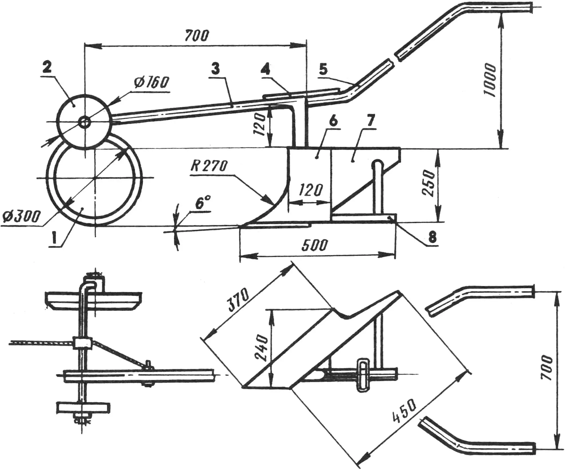
Towed plow:
1 — furrow wheel, 2 — land wheel, 3 — beam stand (made from a section of 22×3 mm steel water-gas pipe), 4 — reinforcement element (16 mm Ø steel rod), 5 — handles (from 22×3 mm steel water-gas pipes), 6 — land board (3 mm St45 steel), 7 — share-moldboard (from a high-pressure gas cylinder body), 8 — slider (30×30 mm steel angle).
However, once the operator releases the “Start” button, SB1 opens and disconnects the starting capacitor. From that moment on, normal motor operation is supported only by Ср.
When any of the “Stop” buttons (either on the panel or remote) is pressed, the starter coil loses power. Contacts K1.1—K1.4 open. The motor stops. It also shuts down if the fuse blows — for example, due to overloads caused by maximum cable tension (330 kgf or more) when hitting a boulder or unremoved root. The winch also disconnects from the power supply if sensitive electronic protection equipment (such as the UZOSH-10.2.010UXL4 unit made in Gomel) reacts to a malfunction — if such a unit was installed (not shown in the illustration).
And lastly, never neglect safety rules — not even for a moment. You’re working with a 220 V electric motor and equipment. This is especially important if the winch is connected directly to the power supply without an isolation transformer and lacks electronic protection. This equipment should only be used for plowing as an exception and with extreme caution. Use personal protection against electric shock (special rubber boots, rubber gloves, etc.). Avoid using the machine in rainy or damp weather at all costs.
Using a metal cable instead of a nylon rope is unacceptable. For greater safety, always work in pairs — never alone. If there’s even the slightest doubt about the rope’s strength, protect yourself and your partner from potential injury if it snaps: at the very least, wear a protective (wire or grid-type, like a hockey mask) face shield. As they say, better safe than sorry.
TECHNICAL SPECIFICATIONS OF THE PLOW-WINCH
- Dimensions during transport (without agricultural tools), mm … 860x500x380
- Weight with plow, kg … 76
- Electric motor … three-phase asynchronous, dust- and moisture-protected, single-phase connection
- Motor power, kW … 1.5
- Gearbox … from “Riga” moped, gear ratio … 37
- Drum rotation speed, rpm … 40
- Average pulling force on cable during plowing, kgf … 280
- Electricity consumption per 100 m² of plowing, kWh … 0.5
- Working plow speed, m/s … 0.3
- Plowshare width, cm … 24
- Plowing depth, cm … 25
- Number of furrows per winch relocation, pcs … 3 – 5
- Power supply voltage, V … 220
- Power cable … 100-meter twin-core, cross-section 1.5 mm2
V. RADKOV
Recommend to read
 “Sawmill” in the yard
Mechanical saws produced by industry certainly make the work associated with preparing firewood for the winter easier. But most of them have one drawback: during operation, the entire unit... TWO PISTONS IN ONE CYLINDER
Our magazine has repeatedly written about the works of children's technical club at HCS Institute of inorganic materials, which for many years was headed by engineer A. S. Abramov. Here...
