I have been passionate about DIY creativity for a very long time. My favorite magazine, “Modelist-Konstruktor,” has contributed greatly to this. I have been subscribing to it since 1972. Following the recommendations and tips from the magazine, I have made many useful household constructions. The largest of them are the Arkhipov tractor (“M-K” No. 1, 1984) and the Gromov all-terrain vehicle (“M-K” No. 1, 1985).
In this material, I want to share with the magazine’s readers one of my creations — a desktop drilling machine. About 20 years ago, it was quite difficult for home craftsmen to purchase such a machine. Nowadays, of course, you can choose and buy a drilling machine to suit any taste. But… first of all, the price “bites” (not everyone can afford it), and secondly, what true DIY enthusiast would go to the store if you can make everything yourself without much trouble: saving money and creating exactly the design you need for the intended work.
I needed a relatively small machine for working on small parts. I went through “Modelist-Konstruktor,” but unfortunately, I didn’t find what I needed: the designs offered in the magazine were mainly based on electric drills, while I had a small “motor” that I wanted to use in my machine.
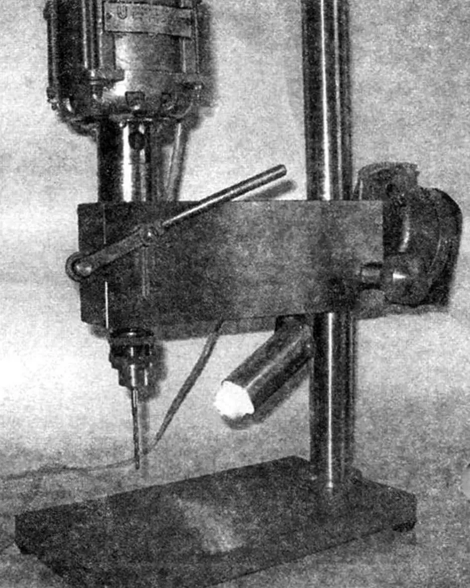
What I ended up with is shown in the photo. Reproducing such a design is not difficult if you have some metalworking skills. Difficulties may only arise in the manufacture of several lathe parts. If you do not have turning skills, you will have to order them from professionals.
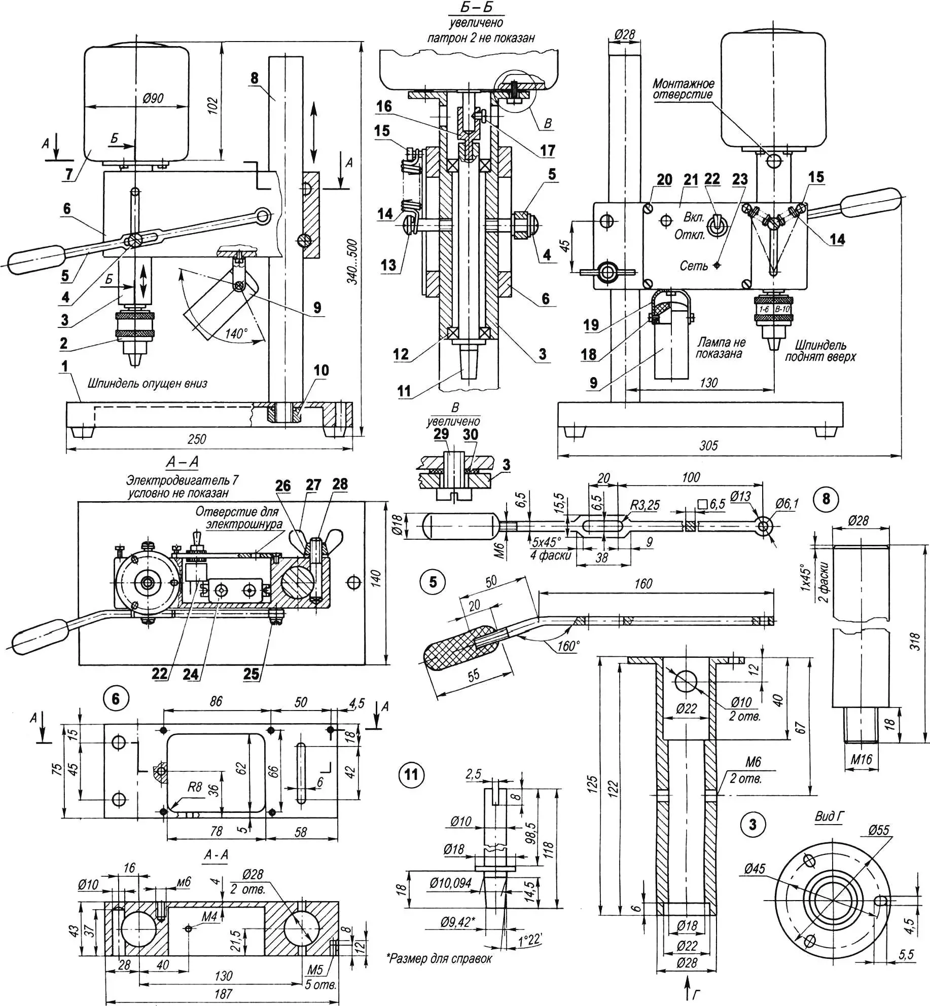
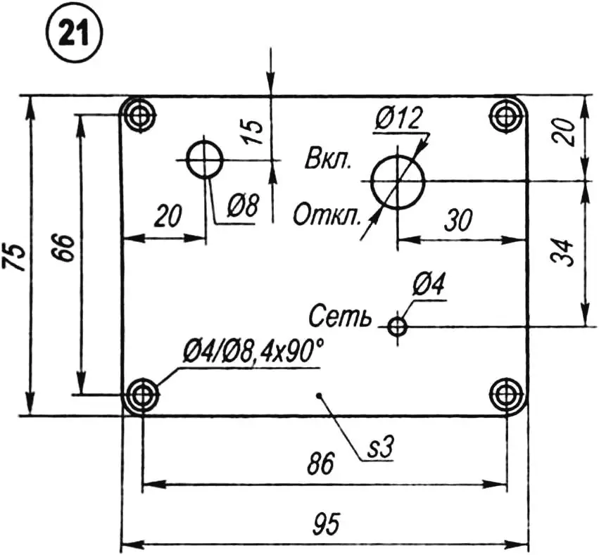
Fig. 1. Desktop drilling machine:
1 — worktable; 2 — drill chuck; 3 — spindle sleeve (steel, Ø55 mm); 4 — handle stop (M6 screw); 5 — feed handle (steel, strip 6×16 mm); 6 — housing (cast iron); 7 — electric motor (KD-50 — from household appliances, N = 60 W, n = 3000 rpm); 8 — column (steel 45, Ø30 mm); 9 — light shade with a small 220 V bulb; 10 — column mount (M16 nut); 11 — spindle (steel 45, Ø18 mm); 12 — ball bearing 1000900 (2 pcs.); 13 — movable spring catch (M6 screw); 14 — spindle return spring (2 pcs.); 15 — fixed spring catch (M4 screw, 2 pcs.); 16 — coupling sleeve (steel, Ø10 mm); 17 — coupling fastening (M3 screw); 18 — lamp pivot axle (M4 screw, 2 pcs.); 19 — lamp bracket (steel, strip 1.2×20 mm); 20 — cover fastening (M4 screw, 3 pcs.); 21 — cover (steel, sheet s3); 22 — power switch; 23 — LED; 24 — capacitor (4 μF); 25 — feed handle axle (M6 screw); 26 — washer; 27 — wing nut M10; 28 — housing lock (M10 stud); 29 — motor fastening (M4 screw, 3 pcs.); 30 — gasket (rubber s2, 3 pcs.)
The base of the machine consists of the table, the column, and the body (bracket).
The table is a heavy steel or cast iron plate. It has two through holes: one for securing the column and another for storing the chuck key — so that it’s always within reach (especially convenient when frequently changing drill bits).
The machine table has four rubber feet — you can use caps from medicine bottles. The feet are attached to the bottom surface through washers using M4 screws.
The column serves for vertical movement of the body and is fastened to the table with an M16 nut with a ground flat surface (for better vertical alignment).
The body is made from a solid cast iron blank. It has two main through holes, 28 mm in diameter: one for the column and one for the spindle sleeve. To allow the spindle sleeve to move up and down over a set distance of 42 mm, slots of the same length and 6 mm width are milled on both sides of the body.
The central part of the body is milled out on one side as much as possible to house the motor start capacitor, toggle switch, voltage indicator, and all wiring. The recess in the body is closed with a plate fastened to the body with countersunk M4 screws.
If the chuck reach does not satisfy the user, the machine can have a greater center-to-center distance, in which case certain dimensions should be adjusted accordingly.
The spindle in the sleeve is mounted on two ball bearings No. 1000900 (10x22x6). Other bearings can also be used, preferably sealed ones, with slight changes to the sleeve dimensions. The spindle end has a shortened Morse taper for a B-10 self-centering chuck. The chuck allows holding tools (drills, countersinks, reamers, etc.) with cylindrical shanks up to 6 mm in diameter. If desired, the spindle can be made for a larger chuck for drills up to 10 mm, but for drilling steel parts, the standard motor will not provide sufficient power.
For lubricating the bearings and spindle sleeve, use Lithol or CIATIM grease.
The KD-50 electric motor — from household equipment — is a fairly common choice: power N = 60 W, speed n = 3000 rpm. It is mounted on the spindle sleeve through three rubber rings. This mounting ensures better shaft alignment. To transmit torque from the motor to the spindle, a bushing is fitted onto the motor shaft (if not supplied). The lower end of the bushing is ground flat as shown in the figure. The upper part of the spindle has a slot into which the ground end of the bushing fits. With proper alignment, such a drive runs smoothly.
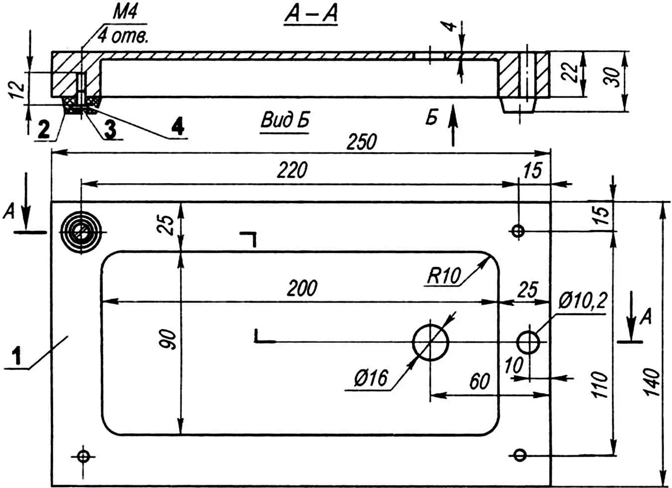
1 — body (steel, cast iron); 2 — rubber foot (4 pcs.); 3 — foot fastening (M4 screw, 4 pcs.); 4 — washer (4 pcs.)
The column is 300 mm high — sufficient for drilling both small and moderately large parts. Moreover, the machine body rotates 360 degrees, so if you place an additional weight on the table, you can easily drill tall workpieces by turning the body in the opposite direction. To fix and hold the body at the desired height, a clamp consisting of a stud, flat washer, and wing nut is used. The stud is installed in one of two blind holes in the body, ensuring secure fastening.
The feed handle can be turned from a bar or cut from a steel strip, with a dielectric grip added. The central part of the handle has an enlarged flat pad with a longitudinal slot. A screw threaded into the spindle sleeve slides along this slot. A hole for the pivot pin is drilled at the end of the handle. On the opposite side of the body, along the vertical slot, another M6 screw moves, to which two cylindrical return springs for the spindle are attached. The opposite ends of the springs are fixed to screws at the top of the body. Instead of springs, an elastic rubber cord or a cut ring from a motorcycle tube can be used.
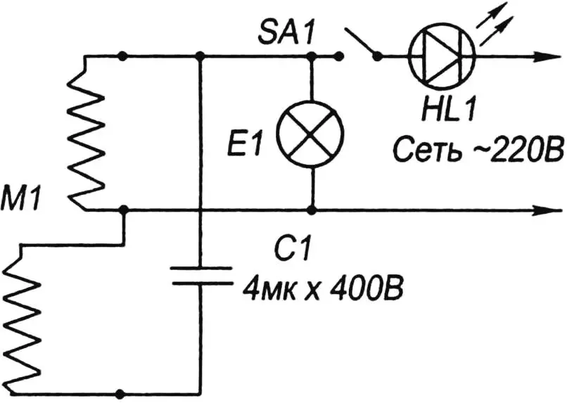
As for the electrical equipment, attention should be paid to the presence of an LED indicator that shows readiness for work, and a small tubular lamp rated for 220 V installed in a homemade tubular shade.
Fastening the shade to the bracket arc with two M4 screws, and the arc itself to the housing, provides the lamp with sufficient freedom of movement and the ability to illuminate the working area well — which is especially important when working with small drills.
To give the machine an aesthetic appearance, it can be painted (except for the column, spindle sleeve, and top surface of the table).
The photo shows a slightly modified version of the machine. The changes are not fundamental. One difference is a different feed handle position — I found it more convenient this way. Another is a heavier round handle instead of a wing nut. The third is fastening the column to the table with three screws through a flange. The advantage here is increased rigidity of the column-table joint; the downside is larger workpiece size and more labor in making the column. In the photo, an attachment is visible on the back wall of the body — a sharpening device for drills and other tools. This attachment is not covered in this article.
This device has served faithfully in my workshop for almost three decades. I wish good luck to everyone who decides to build it.
I. ROSTOVSKY
Recommend to read
 “CHUK AND GEK” — SNOWMOBILE
On the shelves of sports stores you can often see elegant double sledge for skiing the mountains, called "Chuk and GEK". The sleds solidly constructed, brightly colored, very attractive... FURNITURE A “DESIGNER”
As soon as we hear the word "designer" as we have before us the first thing to appear beloved by many children children designers, which are so interesting to collect machines, tools,...
