 The words of the comic song “Without water — and neither the amplitude and no syudy” actually turn out to be quite a serious statement. Where there is water — less and hassle. Where it is not, on the extraction of water is necessary to take care of yourself. Especially large volumes of water need in the summer at the cottage, in the garden, the garden, as many plants require regular watering, because to rely on the timely drop of rain at least naive.
To produce (raise) the water usually falls from the bottom: of the well, wells, rivers, lakes. To raise it to the place of accumulation or consumption of buckets of hard and unproductive, and sometimes impossible (e.g., from wells). To facilitate its delivery up to the required amount are called pumps, types and types of which — a great many. There are even some that use the energy of wind, flowing water and even the sun. But sometimes movement is an indispensable Bicycle and to lift water a conventional piston hand pump is the most appropriate and expedient.
In the proposed setup, he is also present, though not as the main “vaddalias” mechanism, and as an auxiliary. First, hedging main centrifugal electric pump in case of interruptions in the supply of electricity, and secondly, it serves for pre-filling with water dipleg and the entire system to a centrifugal pump could then pump it from the well.
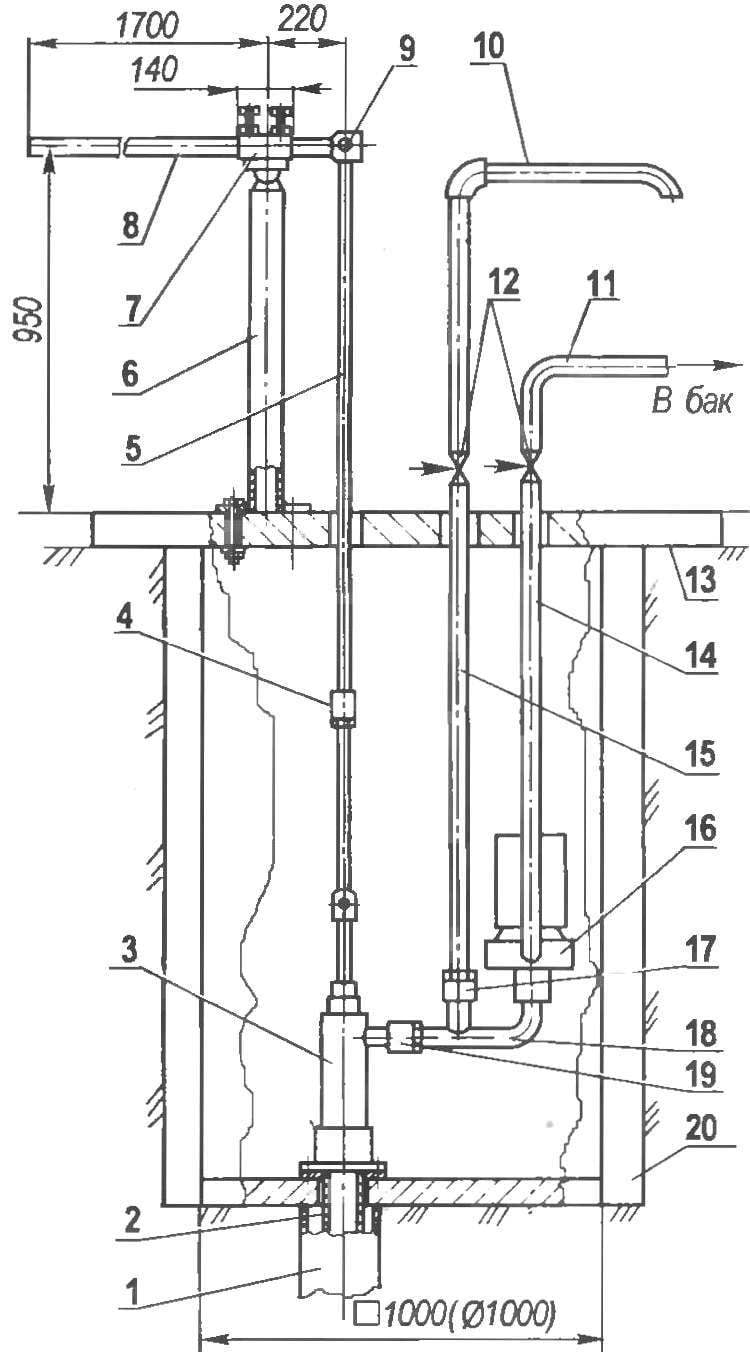
The design feature of the installation lies in the fact that the most difficult (and hence valuable) mechanisms — pumps, both manual and electric, are mounted in fairly deep, closed, concrete slab, concrete pit, inaccessible to unauthorized access to it. That’s important in a country-garden agriculture, which often remains for a long time without supervision Insulation of a pit at such a depth provides nezamerzaika water and year-round operation of the facility.

Water intake installation (diagram):
1 — casing wells; 2 — downcomer pipe (2″); 3 — piston manual pump; 4 the adjusting-coupling (1/2″); 5 — rod (pipe 1/2″); 6 — stand (pipe 3″); 7 — bearing hinge; 8 — the lever-arm (pipe 1/2″); 9 — coupling hinge; 10 — Husak hand pump (tube 1″), 11 — a bypass pipe of the electric pump (1″); 12 — valves (1″); 13 — floor slab of a pit (concrete); 14 — riser electric pump (tube 1″) 15 — the riser of the hand pump (tube 1″); 16 — electric centrifugal pump 17 — coupler 1″; 18 — sliding pipe (pipe 1 1/4”); 19 — clutch 1 1/4″; 20 — fencing of the pit (concrete)
Device centrifugal electric pump is not necessary to describe — it is factory made and no alterations were not exposed. In its place can be set to any other, if only he provided for lifting water from the depth at which it is located, and its performance was commensurate with the needs, which, in turn, are limited to the production of the well.
The manual pump is clear from the drawing, which shows its cut. Images of all Assembly units made to scale relative to each other and attached to the inner diameter of the housing. Pump design, in General, trivial. Compared to such mechanisms, the piston is slightly complicated knot, but it pays a substantial vacuum within the system and high efficiency. This pump can be lift water from depths up to 10 m.

Cutting with manual piston pump (piston is in the lowermost position):
1 — finger with washer and cotter pin; 2 — tip 3 — sleeve; 4 — upper flange; 5 — sealing ring; 6 — gasket; 7 — Welt M14 nut with cotter pin; 8 — rod piston valve; 9 — rubber o-ring piston valve; 10 cuff; 11 — a cover of the piston; 12 — fastening of the piston (M5 screw,4 PCs.); 13 — fastening lower flange (bolt M12 spring washer and nut), 14 — sealing ring flange valve; 15 — the guide sleeve 16 , the lower valve stem; 17 — bottom (flange) valve; 18 — mounting flange with the holiday pipe; 19— a sealing ring; 20 — the bottom flange; 21 —a sealing ring; 22 — piston; 23 — a lock nut; 24 piston valve; 25 — a glass; 26 — piston rod; 27 — the pump housing; 28 — adjustable nozzle; 29 — thread pin M6
As mentioned earlier, the unit can be operated in two modes: manual water injection and an electric pump. At first the valve of the riser of the pump must be closed and opened manually. In this second mode, Vice versa.
Before the swing of the water pump system is filled with water using a hand pump when the closed valve of the riser. Then the handle is installed in the horizontal position (and hence into the piston chamber — intermediate) and turn on the pump.
V. HORT, Kiev


