Dacha plots… Just [~600 m²].
How can you fit a house, a separate kitchen-dining room, a utility block, a bathroom, and a garage on this tiny patch? And you still want to plant something…
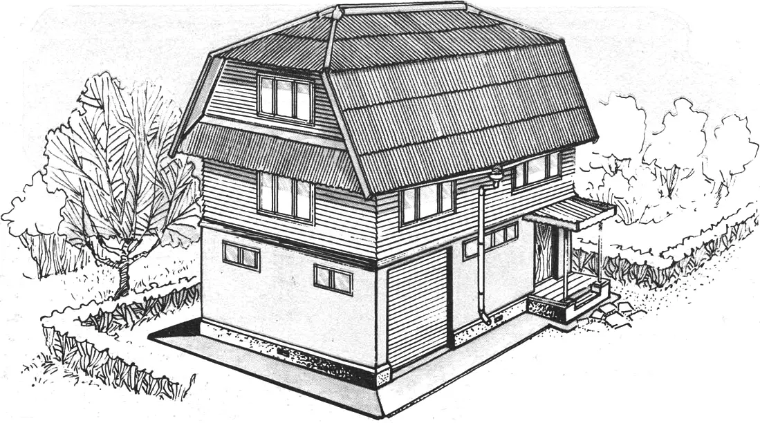
We present a compact three-story cottage house where, under a single roof, all of the above can be arranged quite comfortably. It occupies only 35 m², while the total area of the interior rooms is more than twice that (!). Thanks to a number of structural features, this “skyscraper” does not look like an awkward giant at all.
So, we invite you to take a walk through the house to help you form an idea of it.
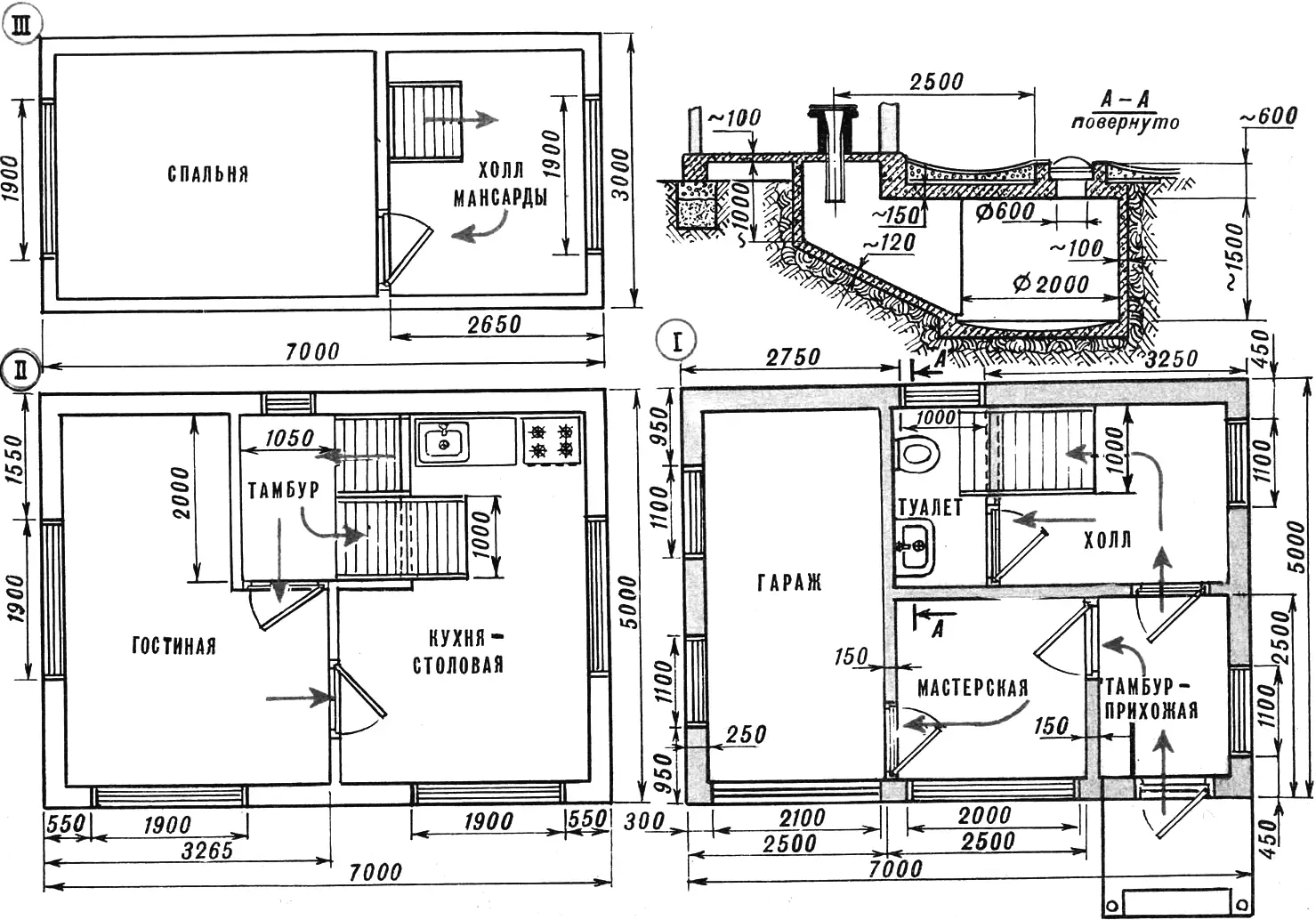
Opening the front door, we enter a small entrance hall of 3.6 m². There is a built-in wall cabinet 1.5 m wide and 0.5 m deep. From here you can go to the workshop (which also serves as a boiler room) of 5.3 m², and from there — to the garage (its dimensions are 2.2×4.5 m, area — about 10 m²).
There is another door in the entrance hall leading to a small hall of 6.0 m²; further on — to the second floor or to a toilet room (3.0 m²) with a luff-type water closet and a washbasin.
Climbing the stairs to the second floor, we find ourselves in a small vestibule of 2.1 m², from which, through a door, you can enter the living room (11.7 m²) and the kitchen-dining room (14.0 m²), and, using a nearby staircase, go up to the last level of the “skyscraper” — the attic. It consists of a 10.0 m² room and a small 6.0 m² hall. The attic space can be used as a children’s room, a bedroom, or a study.
If you add up all these square meters, you get about 72 m². Reminder: the floor area of the house itself is only 35 m².
How to build such a house? Of course, it is not easy and far from cheap, but it will still cost less than erecting the structures listed at the beginning as separate buildings.
Erecting any house begins with laying a foundation. There are many options; choosing the best one is linked to a multitude of various, sometimes mutually exclusive, factors. The main ones are the weight of the house, soil composition, and the depth of groundwater. In this case, the first factor is not the most important, because the house is not very heavy. As for the soil, it is largely what will determine the future of your home. In particular, so-called frost-heaving soils do not allow the use of a relatively inexpensive column foundation, because cyclic temperature changes over the year cause the soil to heave together with the foundation (in that case, the foundation footing is placed below the frost line).
In this sense, a simplified foundation on a sand cushion is almost completely free of drawbacks. Its upper part is a layer made of any inorganic materials: gravel, crushed stone, brick, brick and concrete rubble, and their mixes. The lower part consists of sand — preferably coarse-grained. Such a foundation is reliable, durable, and can be built at any frost depth. The only condition that must be met is that it must be reliably protected from rainwater and flood water.
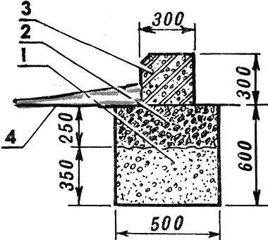
1 — coarse sand, 2 — gravel (brick or concrete rubble), 3 — basement wall (reinforced concrete), 4 — blind area (apron).
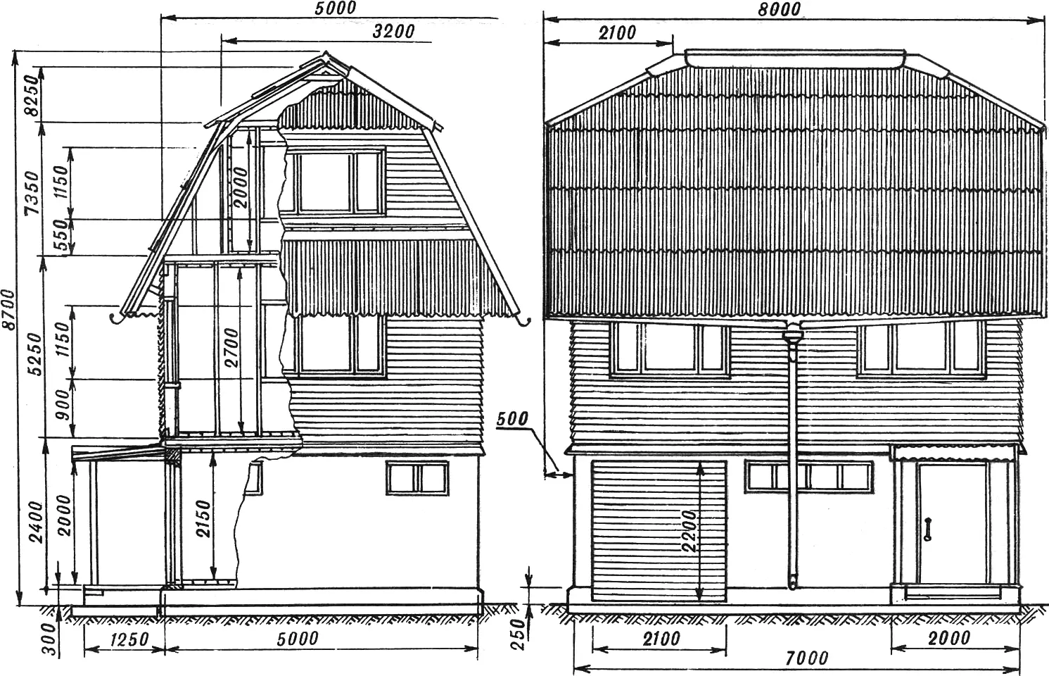
The dimensions of the foundation and basement are shown in one of the drawings. Its footprint must correspond to the basement floor plan.
Foundation construction begins with digging a trench about 0.5 m wide and 0.6 m deep. Several layers of sand are poured into it, watering each layer to promote compaction. Then gravel or another material is laid on top and thoroughly compacted. Make sure the gravel-sand cushion is strictly horizontal — this will simplify further work.
The basement wall can be cast monolithic reinforced concrete (using reusable movable formwork) or built from suitably sized reinforced-concrete blocks. Although the second method is simpler, the first is still preferable and more accessible. Moreover, it allows you not only to obtain a strong basement wall but also to decorate its surface with an original finish. For this, corrugated rubber mats, corrugated fiberglass, or slate are embedded into the outer formwork panel. Before installing the formwork on the gravel cushion, lay polyethylene film — otherwise the liquid fraction of the concrete will sink into the gravel.
When casting the basement wall, it is recommended to use steel reinforcement — scraps of thick wire, pipes, parts of old iron beds, and other suitable scrap metal. In addition, you must provide vents — ventilation openings for subfloor ventilation — as well as holes for threaded studs that will attach supports for floor joists to the basement wall.
After pouring, the concrete mix is thoroughly compacted and worked with a pointed shovel. If the weather is dry and hot for several days, the concrete should be shaded from the sun and watered.
When casting the basement wall at the garage gates, we recommend sinking it together with the foundation so that a car can drive into the garage freely without rocking the basement wall and foundation.
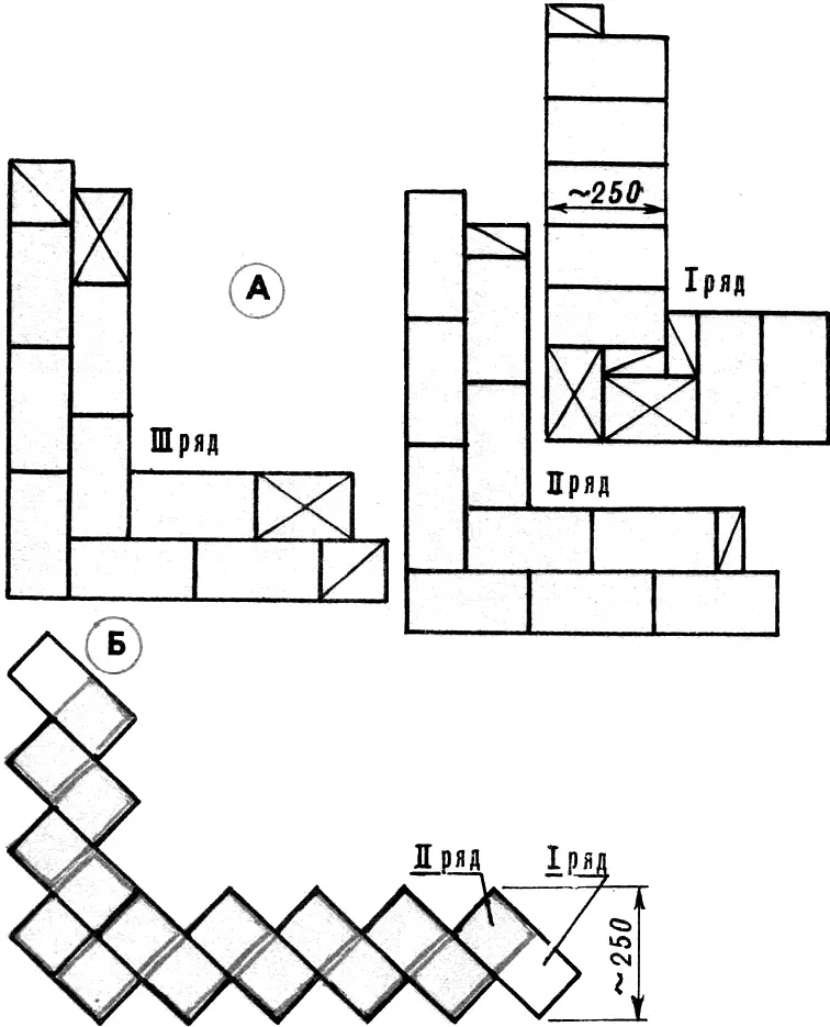
A — “single brick” masonry, B — “zigzag” masonry.
Basement walls can be laid “in one brick” — the thickness will be about 25 cm (the laying pattern is shown in the drawings). Bricks are laid in sequence: first according to row scheme I, then II, III, after which the cycle repeats. You can, indeed, lay only rows I and II — the wall strength will not decrease.
Recently, “zigzag” masonry, shown in one of the drawings, has been gaining popularity. Such a wall has many advantages: attractive appearance, improved stability, good breathability, and, perhaps most importantly, less brick consumption compared with traditional “single brick” masonry.
As for partitions, they can well be built “in half a brick” — the thickness of such a wall will be about 120 mm. When laying walls and partitions, remember the wooden plugs embedded in the vertical parts of door and window openings for fastening door and window frames.
It should be noted that brick is far from the only material for basement walls. Walls can be made of monolithic concrete, or of concrete, slag-concrete, and sawdust-concrete blocks cast in a homemade form — everything depends on your possibilities.
Wall and partition masonry is best done with a cement-sand-clay mortar. If you have M300 cement, the components for the mortar are taken in the following ratio: 1 part cement to 1.5 parts clay and 10 parts sand; with M400 cement — 1 part cement to 2 parts clay and 12 parts sand. Such mortar has satisfactory strength and good plasticity, and can be used within 1—1.5 hours. (By the way, clay in these ratios can be successfully replaced with lime.)
Lintels above windows, doors, and gates are easiest to make from reinforced-concrete beams. True, they do not always come in the required cross-section and length, so they can well be made of monolithic concrete by building formwork above window and door openings or casting a beam separately and then installing it above the corresponding opening. Monolithic reinforced-concrete lintels are less labor-intensive. Only in spans exceeding 2 m should you use quality steel reinforcement, placing it mainly in the lower part of the formwork. The reason is that this part of the beam works in tension, and tensile forces will be carried by the reinforcing bars. Loads in the upper part of the beam (compression) are taken well by the concrete itself.
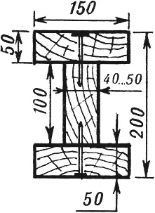
The span length of the basement ceiling joists and the second-floor ceiling joists is 5 m. In this case, wooden beams 150×200 mm in cross-section will be required, provided the spacing between them is 1 m and the total load on 1 m² of the floor is 250 kgf. Wood consumption then becomes unjustifiably high, so we recommend making composite I-section beams. They are assembled from boards 40…50 mm thick using nails and glue. Keep in mind that a poorly glued beam is equivalent in strength and stiffness to three boards stacked on top of each other — clearly insufficient. Therefore we advise using epoxy resin, adding wood flour or cement to reduce flow. Casein glue also works; for better water resistance and reduced flow, it should also be mixed with cement powder until the mixture resembles medium-thickness putty.
If conditions do not allow quality beam assembly, it is safer to stick with solid timber beams.
Before laying ceiling joists along the perimeter of the basement walls, glue two layers of roofing felt using bitumen.
Joists are laid so that the spacing between them is about 1 m. You must account for staircase placement and begin laying from those joists that will form the opening for the stairwell between floors.
If the basement ceiling is brick, it can well rest on partitions. The only place without such partitions is the garage; but above it you can still span one or two reinforced-concrete beams on which the ceiling joists will rest.
It should be noted that wooden I-beams allow you to insulate the floor. You only need to lay a so-called vapor barrier layer of parchment, roofing felt, or synthetic film over the insulation. Mineral wool, foam plastic, or expanded clay can be used as insulation.
Once the ceiling joists are laid, you can proceed with erecting the house proper. It is a frame structure with two-sided wall cladding using lumber (boards) and sheet materials (plywood or hardboard). Frame houses are the most economical in labor and materials, and with effective insulation they are 1.5—2 times lighter and cheaper than log houses. But most importantly — frame walls can be built by hand even by those without professional carpenter skills.
The frame of exterior and interior walls is best assembled from boards 50 mm thick and 100…150 mm wide. The same boards are used for rafters and floor joists. Frame erection begins with installing the bottom sill on top of the basement ceiling joists. Frame studs are placed on the bottom sill; the optimal spacing between studs is 500 mm. With a 1 m spacing between basement and floor joists, the frame yields an optimal load path with clear transfer of loads through the bearing elements of walls and ceilings.
For exterior cladding of the frame, tongue-and-groove boards or non-profiled planed boards are best. Both should preferably be nailed horizontally: tongue-and-groove boards — groove up, non-profiled boards — lapped, overlapping each other. Such cladding reliably protects the wall from rain — including wind-driven rain. For wall insulation, mineral wool boards are best — lightweight, fire-resistant, not destroyed by rodents, and they do not rot.
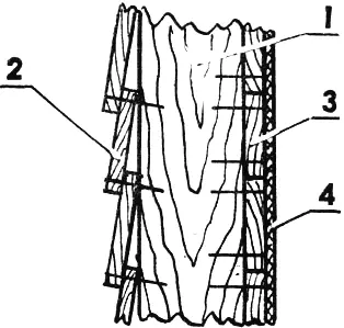
1 — stud, 2 — non-profiled boards of exterior cladding, 3 — boards of interior cladding, 4 — plywood or hardboard.
For interior cladding of the frame, practically any boards, fiberboard and particleboard panels, or plywood can be used.
To ensure durability of the future house, it is advisable to protect its main (especially load-bearing) elements from insects and fungus. Industry currently produces a range of preparations; among the most effective is the liquid “Senezh,” intended for wood impregnation.
The roof of our “skyscraper” is a mansard hip roof. Such roofs are usually built when attic space is used as living space — a mansard. The absence of two small gables above the mansard allows more economical use of lumber and provides protection from rain. Significant roof overhangs (about 1 m) relative to the floor level between the second floor and the mansard also help. Moreover, such overhangs visually reduce the height of the house and give it more harmonious proportions.
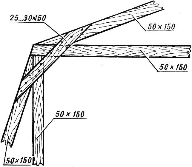
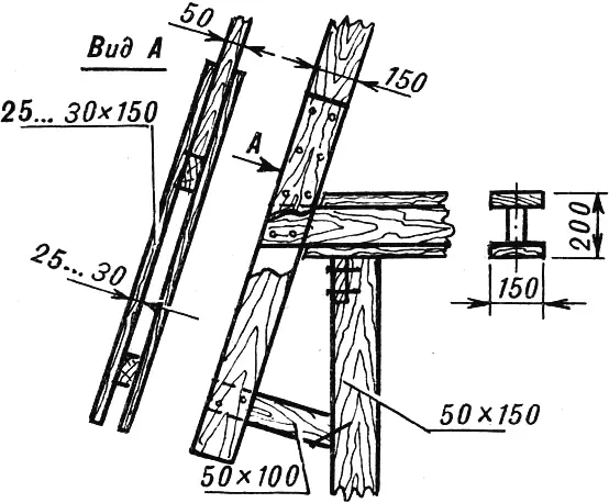
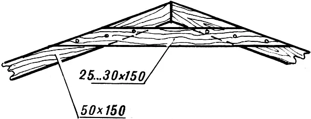
Rafters and other roof frame elements, as already mentioned, are most conveniently made from boards 5×150 mm in cross-section. The main joint designs are shown in the drawings.
For roofing, corrugated asbestos-cement sheets, commonly called slate, are most suitable. For calculation, recall that small-format VO-type sheets (ordinary corrugated) measure 680×1200 mm and weigh about 9 kg; each such sheet covers approximately 0.6 m². In addition, asbestos-cement accessories are produced for ridge coverage, valleys, and finishing around chimney and ventilation pipes. However, obtaining these parts is quite difficult, so it is better to rely on homemade ones made from sheet metal, for example galvanized roofing iron.
The base for asbestos-cement roofing is sheathing of wooden battens (at least 50×50 mm in cross-section), nailed across the rafters. The spacing between battens is (for VO-type sheets) 500…550 mm. Solid sheathing of unedged boards 20…30 mm thick is also acceptable. To achieve tight contact of an asbestos-cement sheet with the sheathing, place a plywood strip 3…5 mm thick under the middle batten (one of the three supporting the sheet).
For tighter jointing of asbestos-cement sheets to each other, they are laid either offset by one corrugation in each subsequent row, or with the mating corners trimmed, aligning the longitudinal edges of all sheets laid higher. This avoids a common mistake where corner joints create a four-layer overlap and wide gaps through which the first driving rain will flood your mansard with water.
Laying VO sheets is best started from the right side of the roof and moved left, overlapping each sheet by one corrugation. The top row must be laid so that the overlap relative to the lower row is 120…150 mm.
Asbestos-cement sheets can be fastened to the sheathing with special nails or screws passed through holes in the crests of the waves. Rubber washers and pads should be used.
We do not address water supply issues, because they depend entirely on whether centralized or local water supply is available on the plot. Running pipes inside the house is not particularly difficult, since they only supply a washbasin in the toilet room and a sink in the kitchen-dining room.
A few words about the sewage system. For our house, a luff-type toilet with a cesspit is more suitable. Structurally, it is an underground reservoir with sealed walls and a bottom. It is best made of reinforced concrete. In frost-heaving soils, the pit depth must be below the frost line. If the groundwater level is higher than the bottom of the cesspit, additional rolled waterproofing is laid along the perimeter of the exterior walls and bottom. The most convenient cesspit shape is cylindrical. With a pit diameter of 2…2.5 m, the reinforced-concrete wall thickness is about 100 mm.
The cesspit must be ventilated. It is best to route ventilation through an internal chimney-and-ventilation duct. This will not be too difficult, since you will most likely place the hot-water heating boiler in the workshop room, close to the toilet room.
“Modelist-Konstruktor” No. 1’96, design by I. EVSTRATOV
Recommend to read
 TURBINE IN THE FIELD
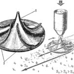
Existing disk device for mechanized spreading of fertilizers do not always provide the uniformity and range of distribution of fertilizers on the field. Young innovators of the... “CIRCUS” FROM LEICHERT
Enlisting in the First world war, the warring countries have moved from a flat ground-water surface warfare in three-dimensional space: clumsy aircraft, recently entertained the public...
