Several years ago, our family purchased a summer cottage that had not been cultivated for a long time. An attempt to dig it up by hand was unsuccessful and we were forced to hire people who plowed our site with a walk-behind tractor. They paid a decent amount for this. And then I thought that in the future it would be nice to have my own walk-behind tractor – after all, it can help throughout the season.
After shopping around power equipment stores, I realized that purchasing a motorcycle assistant and attachments for it would be beyond my means. And since I was interested in technology since childhood, I decided to try to make a walk-behind tractor myself.
At that time, I did not yet have experience in creating my own agricultural machinery, nor, indeed, did I have any idea of how walk-behind tractors work. Then I turned to the publications of the respected “Model Designer”. Having chosen the most interesting, in my opinion, models from the magazine, I carefully re-read their descriptions and studied the drawings. As a result, I decided to settle on the design described in No. 10’99 “M-K” in an article by V. Petrov entitled “ First of all, a walk-behind tractor .” It seemed to me quite successful, and the drawings were very detailed, for which many thanks to both the author and the magazine. It took about six months to create the walk-behind tractor, and in the spring it was ready for testing.
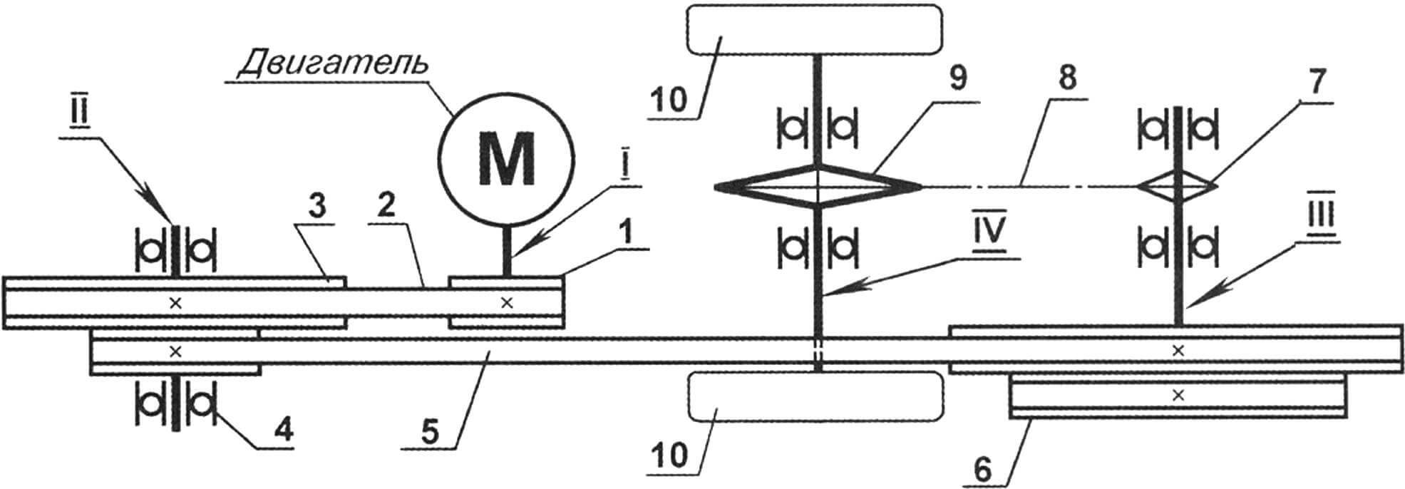
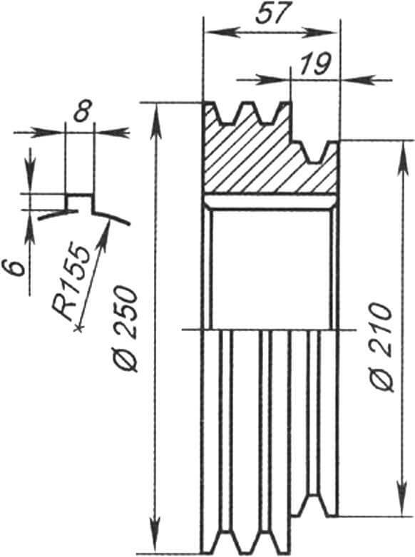
I—motor output shaft; 1 – 1st stage drive pulley; 2 — V-belt profile A, L=800; II – intermediate shaft; 3 — intermediate shaft pulley block; 4 — rolling bearing (6 pcs.); 5 — V-belt profile A, L=1500; 6 — double-groove pulley of the drive shaft of the chain drive; III – drive shaft of the valuable transmission; 7 — drive sprocket of valuable running gear z=11; 8 – chain, t=19.05; 9 — driven sprocket of the running chain drive, z=44; IV – drive shaft of wheels (or cutters); 10 – wheels or cutters
Separately, I note that changes had to be made to the design, since it was not possible to find a motor with its own forced air cooling and at first I installed an engine from a Minsk motorcycle on the walk-behind tractor. To blow over the cylinder, I mounted an electric fan from the “stove” of a Moskvich car and knocked out a casing from an aluminum sheet.
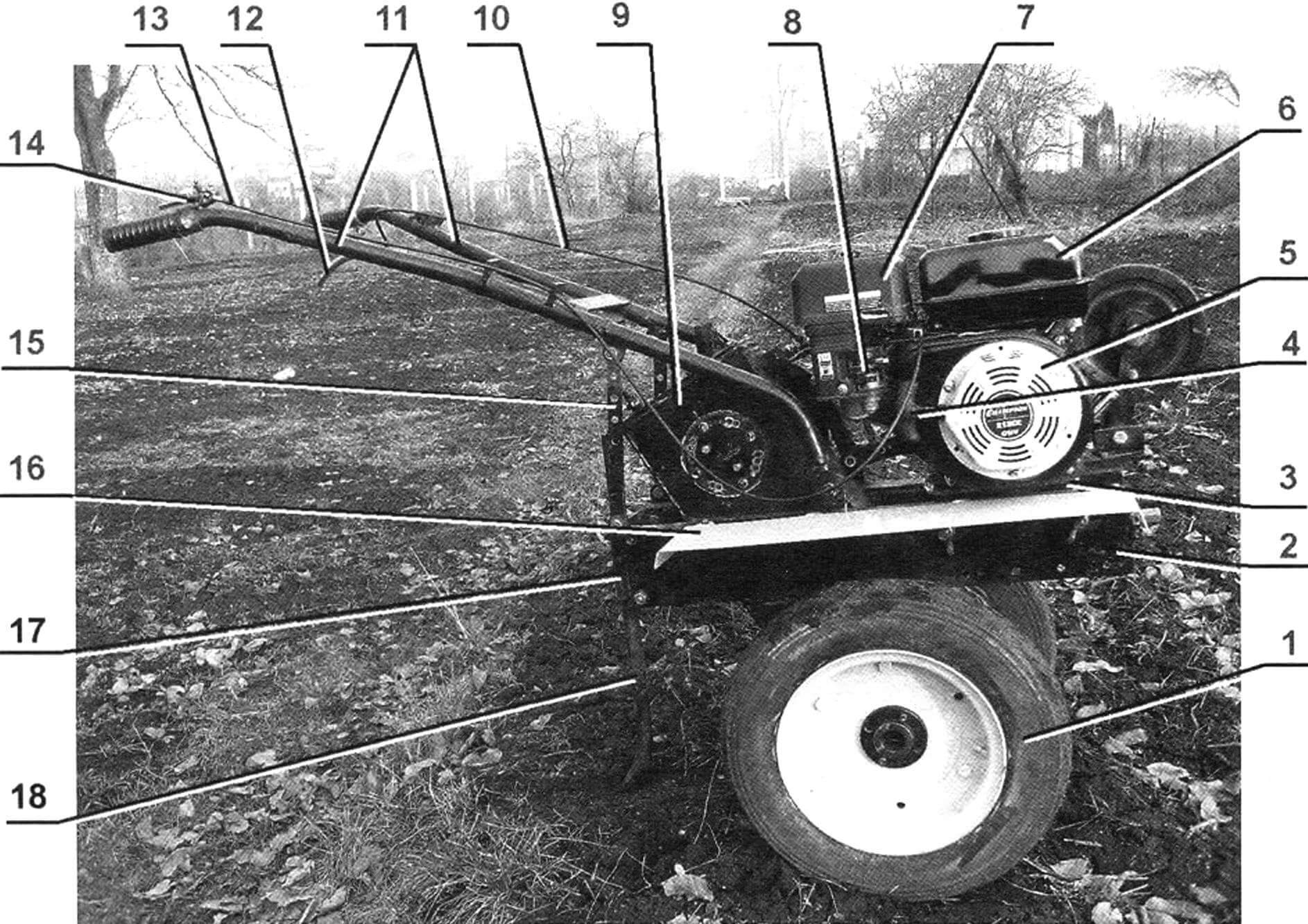
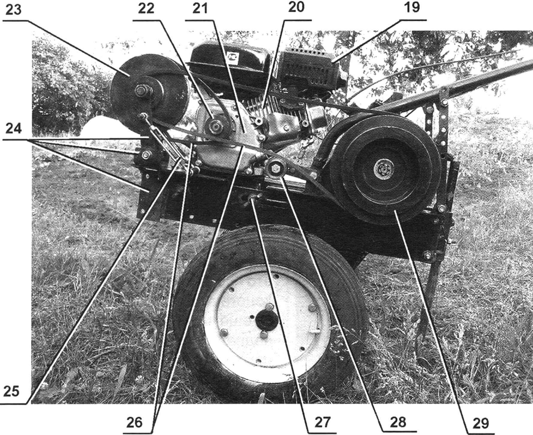
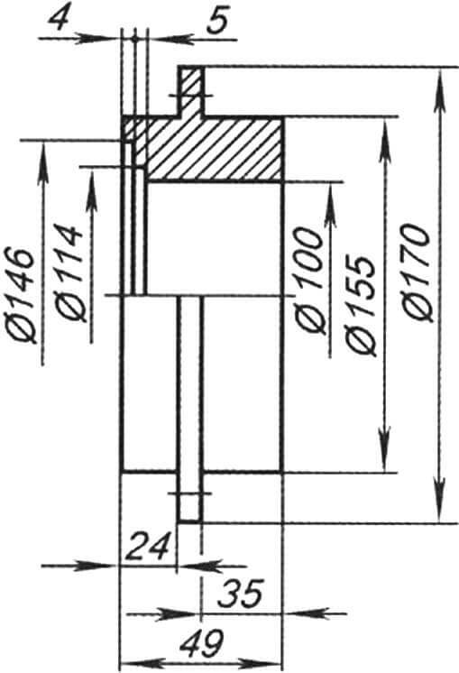
1 — wheel (from the S3D stroller, 2 pcs.); 2 — frame spar (channel No. 6.5, 2 pcs.); 3 — under-engine plate (steel, sheet s5); 4 — starting handle; 5 — forced air cooling system of the engine; 6 — fuel tank; 7 — air filter; 8 — engine power system; 9 — chain drive casing; 10 — clutch cable (motorcycle); 11 — steering rod (pipe Ø32, 2 pcs.); 12 — clutch lever; 13 — throttle cable (motorcycle); 14 — “gas sector”; 15 — bar for adjusting the position of the steering rod (steel, sheet s5, 2 pcs.); 16 — wing (steel sheet, s1.5, 2 pcs.); 17 — parking support-brake bushing (pipe Ø21×2); 18 — parking support-brake; 19 — engine muffler; 20 — engine cylinder; 21 — engine crankcase; 22 — drive pulley of the 1st V-belt drive (engine output shaft pulley); 23 — block of pulleys for the intermediate shaft of V-belt drives; 24 — intermediate shaft suspension unit; 25 — lanyard for tensioning belts (12 pcs.); 26 — transmission belts; 27 — wing nut for fastening the engine subframe (4 pcs.); 28 — tension roller of the 2nd clip-belt drive; 29 — two-strand (driven) block of pulleys of the 2nd V-belt drive
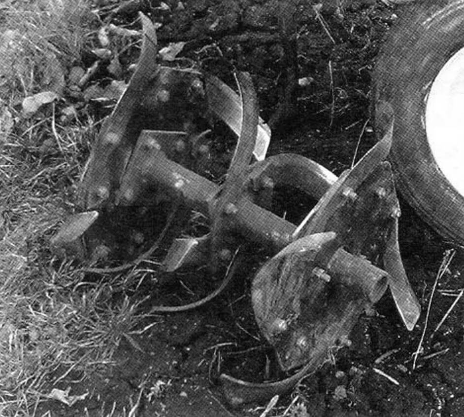
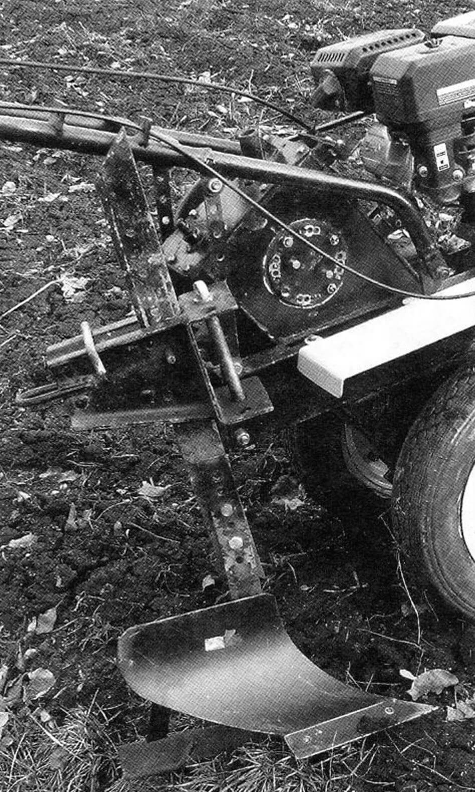
He also made cutters of his own design, the working width of which was about 1 m. But tests showed that the diameter of the cutters was too small and the walk-behind tractor skidded in place because it sat on the gearbox, and the motor was not new and therefore often failed.
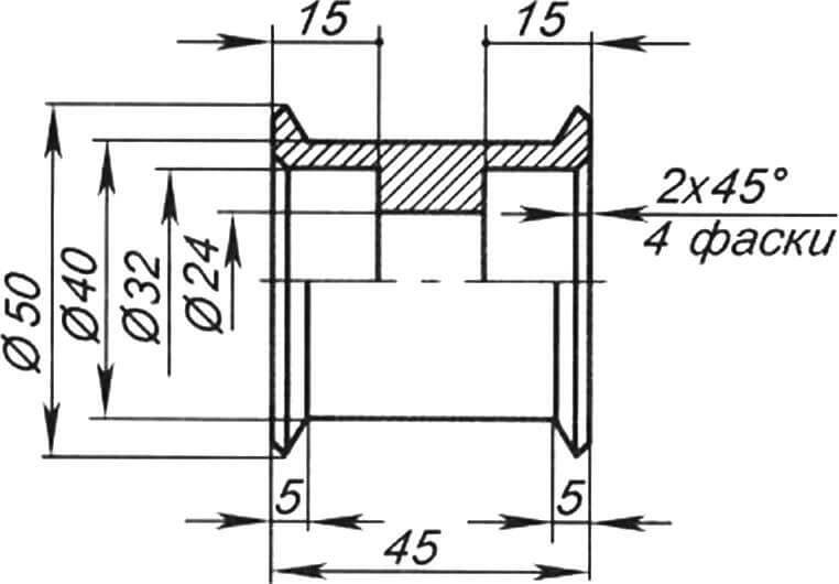
1 – plate (steel sheet, s5); 2 — spacer (channel No. 6.5); bushing (pipe Ø26, 2 pcs.)
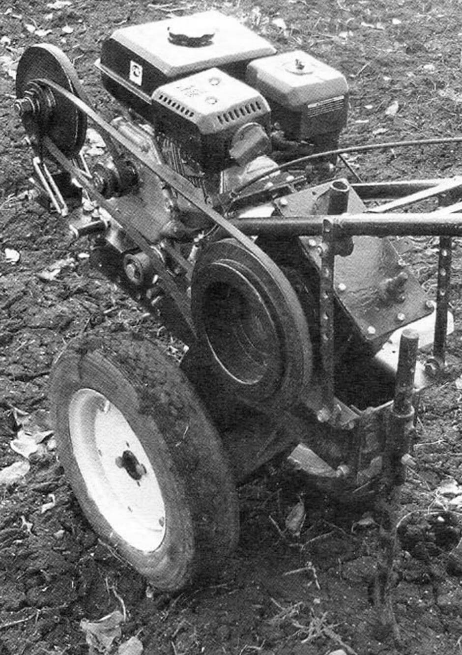
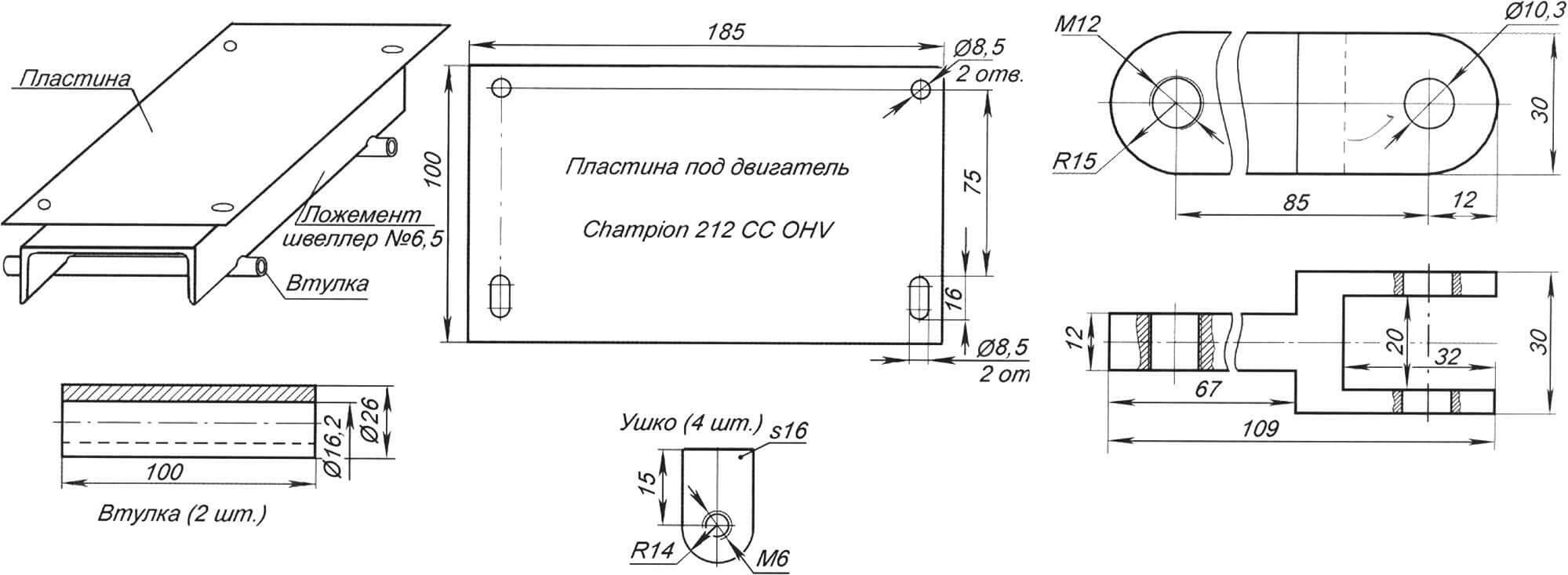
I decided to remake the walk-behind tractor for the next season. I modified the cutters: using special spacers (additional flanges), I increased their diameter. I purchased a new single-cylinder four-stroke engine “Champion” 212 CC OHV with a power of 7 hp. made in China. Instead of sprockets, double-groove pulleys were machined, a V-belt was purchased, and a tensioning device was mounted from a pair of turnbuckles. I also made a new sub-frame with a platform for mounting the engine.
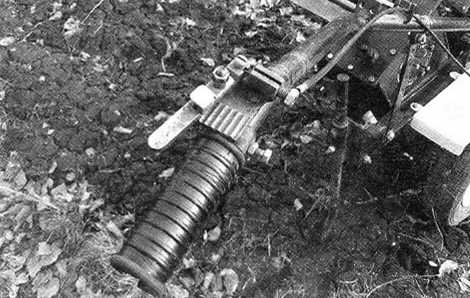
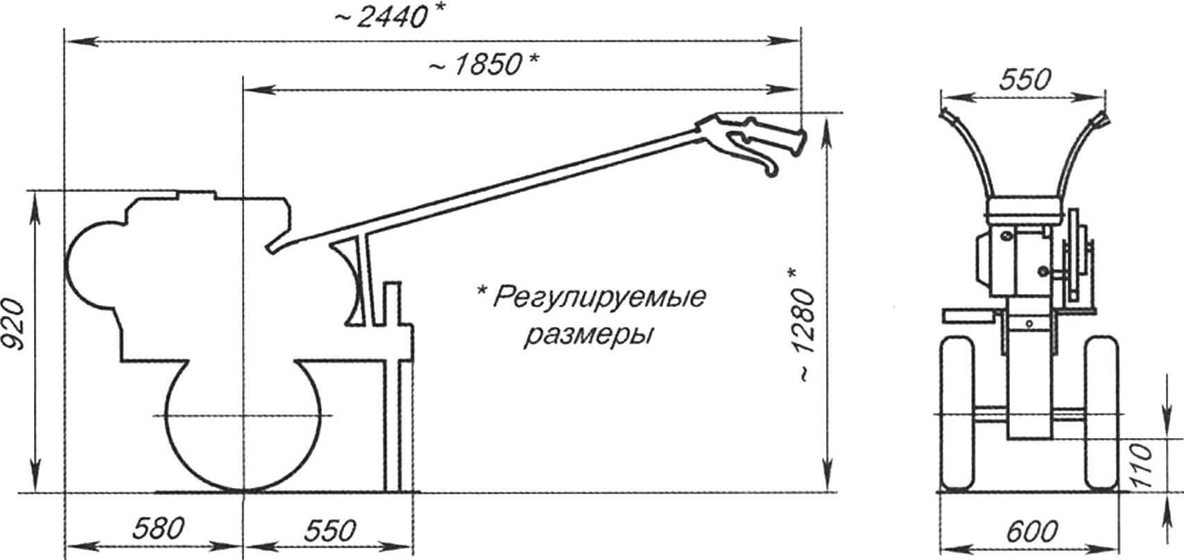
When everything was assembled and it was necessary to move the walk-behind tractor from the workshop to the garden, the unexpected happened… not only was its engine unable to rotate the cutters, it was also unable to drag itself even on wheels on the asphalt – the engine simply stalled when trying to start. I contacted the store where I purchased the engine. There they told me that the motor was in good working order, but most likely there was not enough power and they advised me to purchase a gearbox for the engine, but its price was comparable to the cost of the motor itself. I didn’t buy a gearbox, but a friend helped me solve the problem and advised me to make an additional pulley. The pulley was installed through a bracket on the frame, and the belt was tensioned using two lanyards, which I purchased at a construction base. This pulley is connected to the motor mount output shaft pulley by a profile “A” V-belt with a length of 800 mm, and to the main gearbox by a profile “A” belt with a length of 1700 mm. Only this was not enough. But since the frame prevented the pulley from being enlarged, it was necessary to replace the running chain drive with a different gear ratio: with a number of teeth z = 14 and z = 44 and a pitch t = 19 mm. And everything worked. I also shortened the handles a little and made a new bracket for the “brake” (it’s made from a rod with a diameter of 30 mm), which made the design a little lighter and improved control.
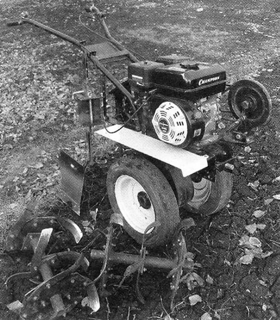
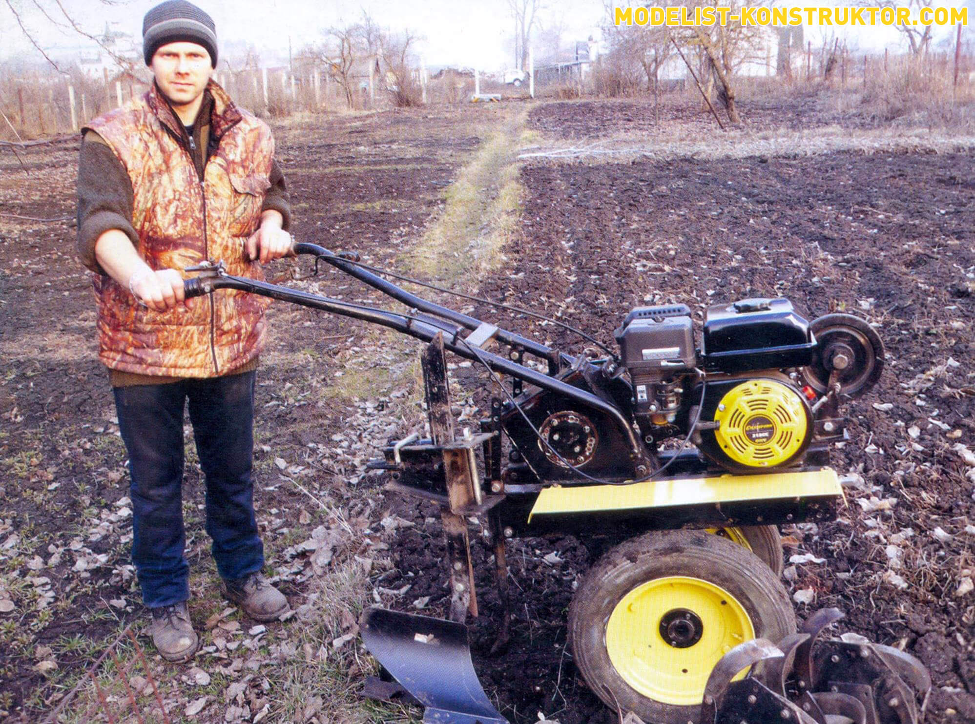
In general, the walk-behind tractor turned out to be quite good, and after painting it generally looks like it was purchased. For several years now he has been helping not only me, but also many of my friends and relatives to cultivate their plots. The walk-behind tractor is quite economical and has two forward gears, which are “switched” by moving the belt along the pulley grooves on the drive shaft of the V-belt drive.
In fairness, it is necessary to note the shortcomings of the design I made. The entire frame can be made of metal 3 mm thick – this will reduce the weight of the entire structure and make it easier to control. And the walk-behind tractor really lacks reverse gear, since it can be problematic to pull out buried cutters.
A. REPIN, Mtsensk, Oryol region.
Recommend to read
 SELF-MOVING STROLLER
Sincerely hope that this vehicle will never need you. But this does not mean that it does not need anyone. There are many people with disorders of the musculoskeletal system, or simply... CURTAINS ON “AGRIMONY”
It is believed that creates a cozy apartment curtains — case female. But hanging them seemingly male? However, I want to share my female experience, how to solve the problem about...
