Automotive design is a long-time passion of Krasnoyarsk resident Vladimir Aleksandrovich Gassan. Readers interested in homemade cars will probably remember both “ Mini-Valga ” and “ Buggy-350 ”… And here is another, just completed work. But unlike the previous ones, where V. A. Gassan was both a developer and a builder of cars, here he acts as a performer – Vladimir Aleksandrovich’s son, automotive engineer Vladimir Gassan, took on all the design and engineering work.
And so, a family debut.
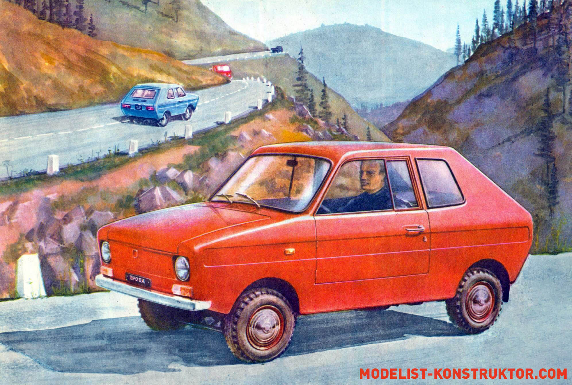
Many years of experience in operating the Mini-Valga have shown that its speed, reliability, and comfort fully satisfy the requirements for a city car. The only thing that didn’t suit me was the body. I wanted to have a car with modern shapes and proportions. After some calculations, I settled on a “combi” body type.
When developing the new model, we used those design solutions that stood the test of time on the Mini-Valga – spark plug suspension, front and rear axles, steering and braking system. Even the engine was left the same – Izh-P-3 from a motorized stroller. This is easy to justify: a simpler and more suitable two-stroke engine does not yet exist, and others (Izh-10 or Izh-P-Sport) cannot be installed on a car without serious modifications.
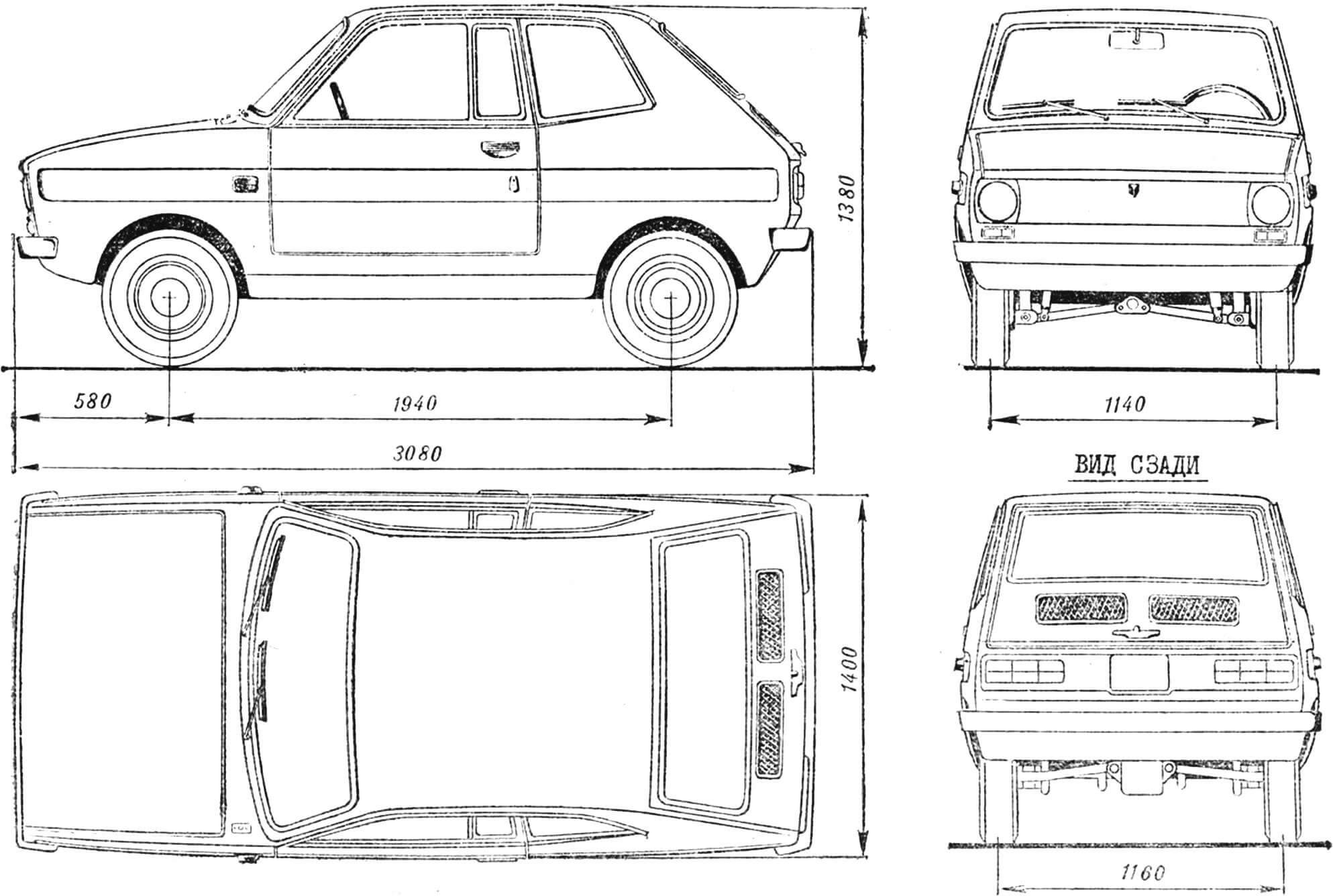
“Valga-combi” is a two-seater mid-engine car with rear-wheel drive. Compared to the Mini-Valga, it is 50 mm higher, 70 mm wider and 150 mm longer. The gas tank capacity has been increased to 18 liters. Instead of a V-shaped windshield, it became possible to install glass from a Zaporozhets (ZAZ-968).
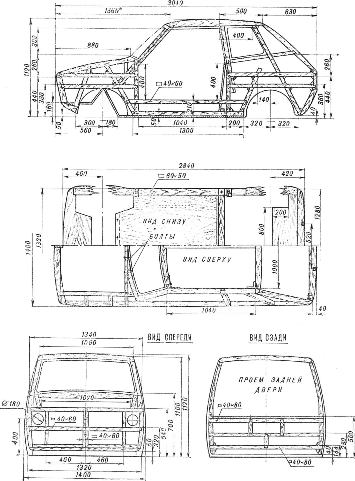
The BODY of the car is three-door, all-wood. The frame is assembled from pine and birch bars, tenoned and half-timbered using epoxy glue, secured with screws. The cracks where the bars join are sealed with mastic made from epoxy glue and sawdust. The body skin is made of three-millimeter plywood. The bottom, as well as the front and rear walls of the cabin are covered with 10 mm thick plywood. All irregularities and joints of the sheets are leveled with epoxy putty, then the entire body is covered with two layers of fiberglass. The final operations for finishing it are coating with GF-20 primer, leveling with nitro putty, cleaning and painting with nitro enamel. The underbody, front wall and outer surfaces of the mudguards are coated with rubber-bitumen mastic.
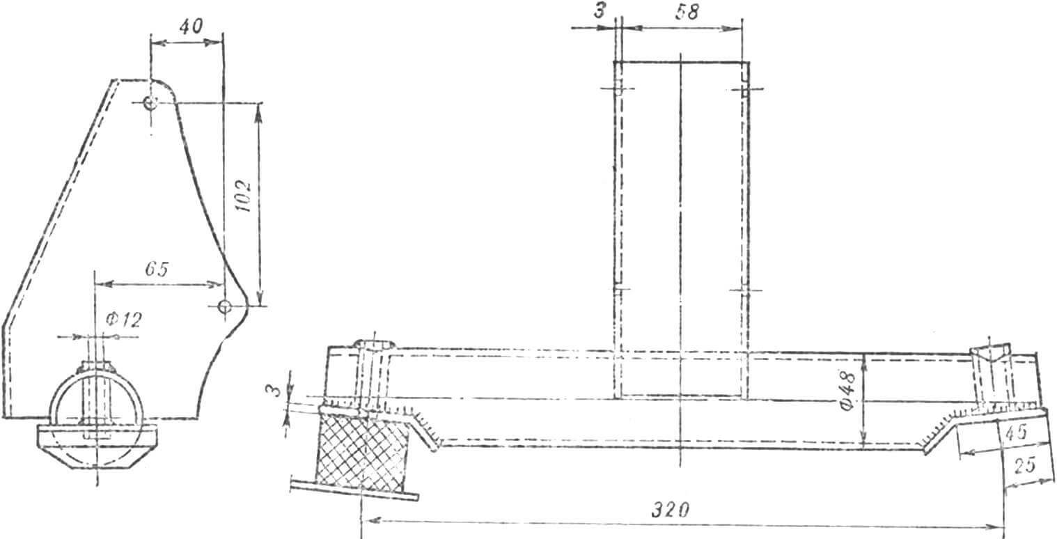
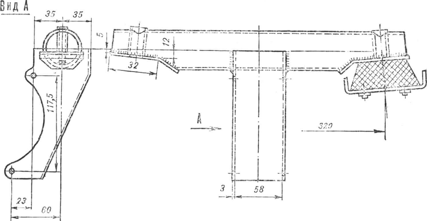
The car frame is welded from steel pipes. Its basis is the frame from the TG-200 “Ant” cargo scooter, the front part of which was cut off, and in its place a Ø72 mm pipe with parts for fastening the front axle was welded. In the rear part of the frame, the central longitudinal pipe was removed, and instead of it, two Ø48 mm pipes were welded at a distance of 250 mm from the longitudinal axis of the frame. The cross pipe in the middle part of the frame is extended on both sides with inserts to a size of 1320 mm; Platforms for joining the frame to the car body are welded to its ends. The platform for the front engine mount is located on the lower inclined pipes of the frame, while the rear engine mounts are fixed on platforms welded to the rear cross member of the frame.
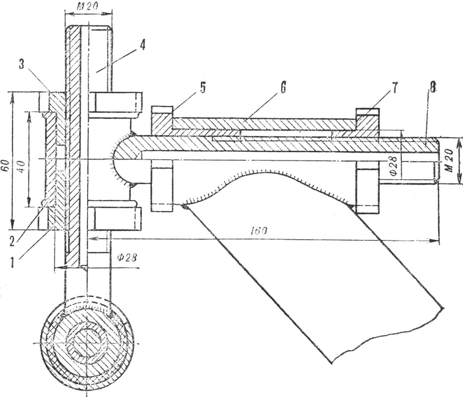
The FRONT AXLE of the car is made according to the “swinging spark plug” pattern. The pipes of the front fork of the M-106 motorcycle (together with oil seals and bushings) and the rear suspension balancers from the SZA motorized stroller were used for it. The modification was as follows. The lower tips of the movable pipes of the fork are cut off, and instead of them, support knuckles are welded, with the help of which the struts are pivotally connected to the balancers. The upper ends of the fixed pipes, after trimming, are used as clips in the camber adjustment units of the front wheels. The upper rings of the elastic suspension hinges are welded to their ends (L = 370 mm). Rubber bushings from the Volga GAZ-24 suspension and springs of the rear suspension of the ZLZ-966 car, shortened to 280 mm, are used as elastic elements, which are fixed to the suspension struts using steel cups. In this case, the upper cups are welded to the rims of the upper elastic hinges, and the lower ones to the stockings of the movable pipes. The lower ends of the latter, together with the stockings, are welded to the support fists. A steel clip with the upper pin of the steering knuckle strut is first put on each stocking and welded. After this, the stocking with the cup is placed on the movable pipe.
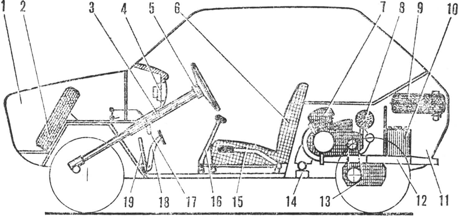
1 — front trunk, 2 — spare wheel, 3 — switch panel, 4 — instrument set, 5 — steering wheel, 6 — seats, 7 — Izh-P-3 engine, 8 — G-108M generator, 9 — fuel tank, 10 — battery, 11 — rear trunk, 12 — muffler, 13 — final drive from the TG-200 scooter, 14 — front engine mount, 15 — reverse gear lever, 16 — gear shift lever, 17 — parking brake lever, 18 — clutch and brake pedals, 19 – gas pedal.
The front suspension strut from the SZD motorized sidecar assembled with the steering knuckle and upper bushing is put on the fingers of the stocking and the steering knuckle, and only after that the stocking is welded to the support knuckle. This assembly technology makes it possible to strictly maintain the distance between the fingers of the fist posts.
The SZA suspension balancers can be modified as follows. First of all, the suspension is completely disassembled. Next, parts of the hubs with the brake drum cover and the rubber bushings are cut off from the balancers. Then the mounting cheeks of the front suspension struts and the lower pins of the hydraulic shock absorbers, made of sheet steel, are welded to the balancer hub.
In place of the standard clips, new ones should be welded, turned on a lathe, into which two rubber bushings from GAZ-24 springs are inserted.
To ensure the ability to adjust the ground clearance and camber of the front wheels during vehicle operation, additional adjustment units have been introduced into the front axle design. Thus, the camber angle can be changed using clips welded to the ends of the front cross member of the frame, inside of which there is a screw with a nut: by rotating them, the output of the adjusting screw from the guide sleeve increases or decreases. The selected camber is secured with a locknut.
The clearance is changed using an adjusting unit – a support coupling with a screw welded to it and a nut with a lock nut in the cage. The latter is welded to the camber correction screw of the front wheels.
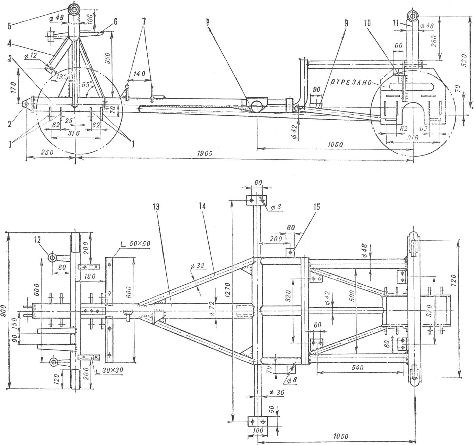
1 — mounting eyes for front balancers, 2 — towing bracket, 3 — front frame tube, 4 — steering gear housing mounting bracket, 5 — front transverse frame beam, 6 — front body support, 7 — brake master cylinder brackets, 8 — main platforms body mounts, 9 — front engine mount, 10 — rear engine mount, 11 — rear suspension strut brackets, 12 — upper front shock absorber mounts, 13 — frame spinal tube, 14 — struts, 15 — rear body mounts.
The front axle is assembled as follows. The assembled swivel assembly of the front axle SZD (steering knuckle, its strut with the upper bushing and the king pin) is put on the pins of the suspension strut stocking and the support knuckle and is secured on the lower pin with an M12 bolt, and on the upper pin with a cotter pin. Rubber bushings from the Volga are placed in the support knuckle cage; a steel spacer sleeve is pressed into their channels. 120-150 ml of MG-8 oil is poured into the internal cavity of the movable pipe. A spring is inserted into the lower cup, through which a stationary pipe with a piston, bushing and oil seal is passed. After the stationary pipe is inserted into the movable pipe until the spring stops in the upper cup, the seal ring is screwed onto the movable pipe. Rubber bushings are placed in the upper ring of the stationary pipe, and spacer bushings are pressed halfway into them. Then a support coupling with a clearance adjusting screw and an adjusting nut screwed onto it is inserted into the upper cutout of the holder, and an M12 mounting bolt is inserted into the spacer bushings and the support coupling, with the help of which the bushings are finally pressed into the upper holder, and their ends fit into the support channels until they stop. couplings. Having completed this operation, the mounting bolt should be replaced with a coupling bolt (Ø12 mm, l = 130 mm).
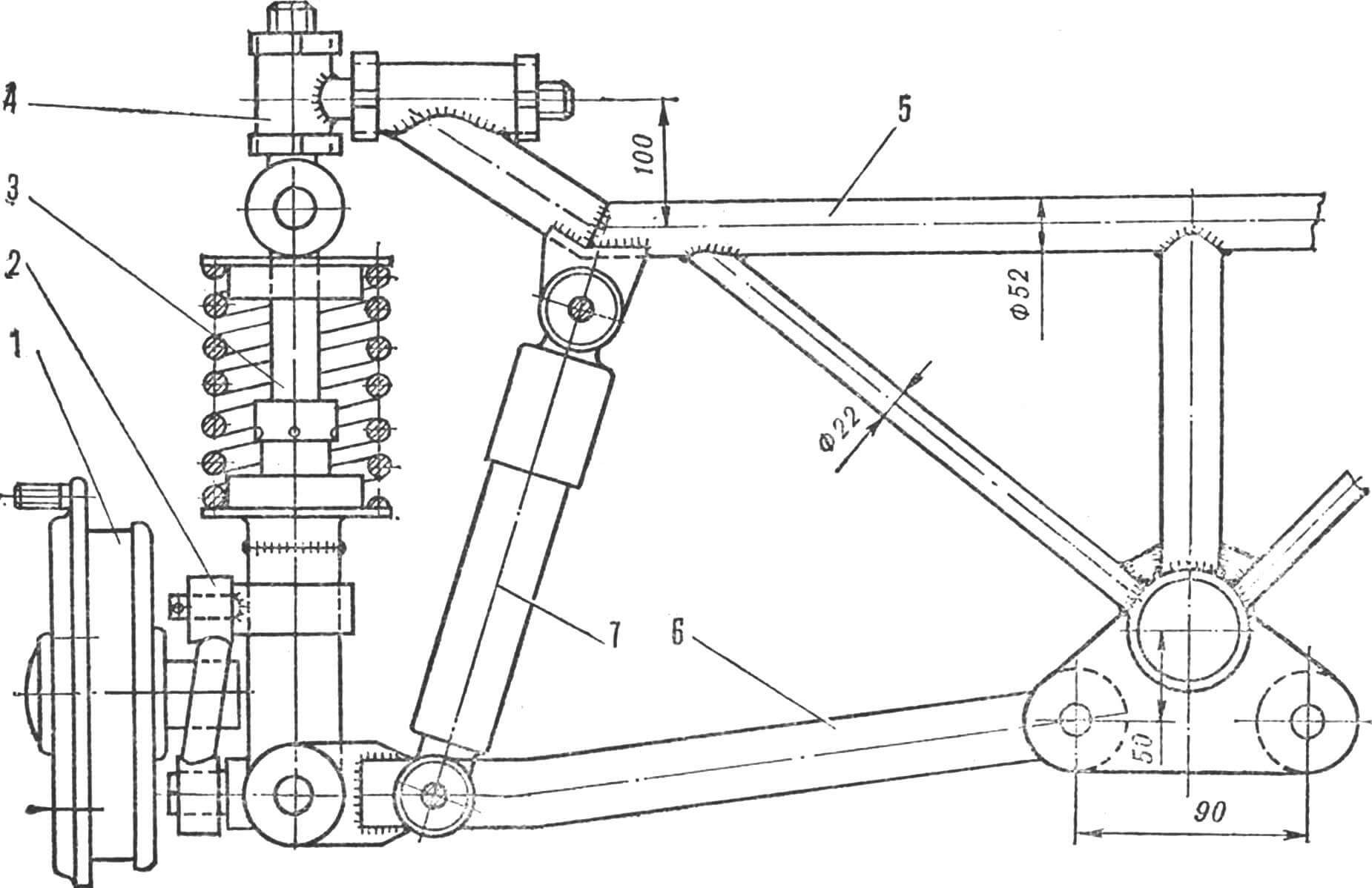
1 — brake drum with hub and disc, 2 — steering knuckle strut, 3 — front suspension strut, 4 — clearance and camber adjustment mechanism, 5 — front frame cross member, 6 — balancer, 7 — hydraulic shock absorber.
The spacer bushings are also pressed into the bushings of both balancers; the latter are inserted into the frame eyes with clips and secured in them with M12 bolts and cotter pins.
The front suspension struts are inserted with their lower ends between the cheeks of the balancers and secured with a coupling bolt.
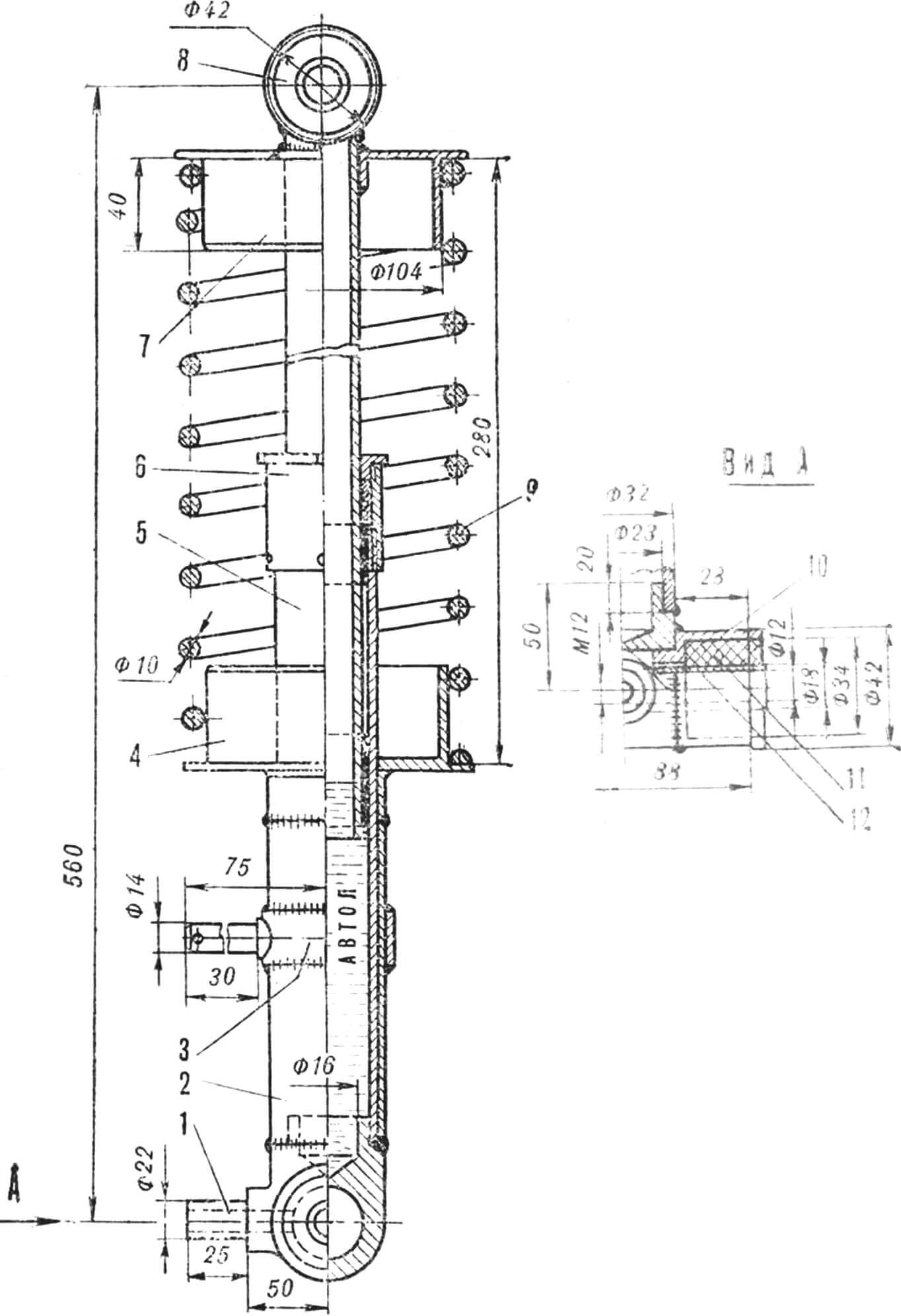
1 — support fist, 2 — stocking of the movable pipe, 3 — clip, 4, 7 — spring mounting cups, 5 — movable pipe, 6 — oil seal, 8 — upper race of the rack, 9 — spring, 10 — support fist clip, 11 — rubber bushing, 12 – spacer bushing.
The clearance adjustment screw is deepened until the adjustment nut stops in the cage of the front wheel camber adjustment mechanism previously assembled on the front cross member of the frame and is secured with a lock nut.
REAR AXLE . Its design is similar to the front one, with the only difference being that the length of the fixed pipes of the racks is 300 mm. The shock absorber springs are from ZAZ-966, they just had to be cut in half. The units for adjusting the ground clearance and wheel camber are the same as those on the front axle. The rear wheel balancers have been modified. Just like the front ones, they have the rubber bushings cut off, and in their place larger diameter clips for rubber bushings from the Volga are welded. At the front ends of the balancers, two cheeks made of sheet steel 5 mm thick are welded on top with Ø12 mm holes for a bolt securing the lower end of the suspension strut to the balancer, which, unlike the front one, instead of a support cam at the lower end, has a clip with two rubber bushings from the Volga. with spacer bushings pressed into them.
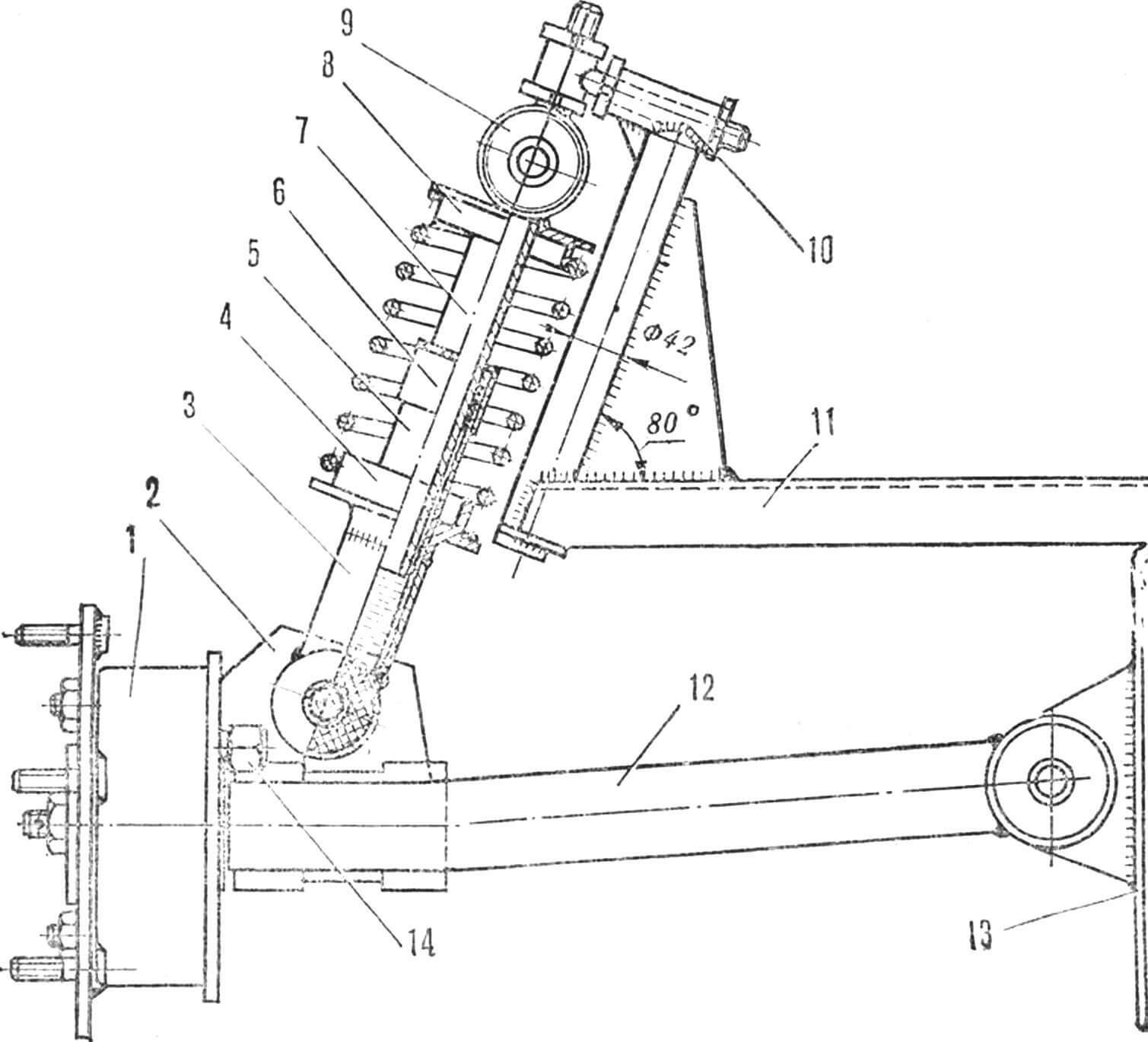
1 – brake drum with disc, 2 – cheeks for attaching the rear suspension strut to the balancer, 3 – strut stocking, 4, 8 – support cups, 5 – movable pipe, 6 – oil seal, 7 – fixed pipe, 9 – upper support of the suspension strut with clearance adjustment mechanism, 10 — strut mounting clip, 11 — rear frame cross member, 12 — balancer, 13 — mounting cheek for the balancer and final drive, 14 — brake hose fitting.
The rear brakes have undergone a radical alteration – instead of mechanical ones, hydraulic brakes from the SZD motorized stroller are installed. To do this, the covers of the mechanical brake drums were removed from the balancers, and in their place adapter flanges for the hydraulic brake covers were welded. The conversion process is described in sufficient detail in the article “Buggy-350 – a sports car for sixteen-year-olds” (“M-K” No. 7, 1979).
The procedure for assembling the rear axle is practically no different from installing the front one.
CONTROLS . The steering shaft was borrowed from the SZD motorized stroller; it had to be lengthened by 50 mm and enclosed in a duralumin casing, at the upper end of which the direction indicator switch was attached. The accelerator pedal is from a GAZ-51 car, the drive cable is from the SZD. The clutch is cable driven, from the SZD. It consists of a homemade pedal, a stop at the front end of the cable, a stop at the rear end of the cable with an adjusting screw and a standard clutch release lever on the engine.
The brake drive is separate for the front and rear wheels, hydraulic. The main brake cylinder is from ZLZ-968, the wheels are SZD st with hoses from GAZ-51, the fittings of which have a new thread M12X1. The main brake cylinder is mounted on a bracket welded to the frame, a rocker arm is installed on the second bracket on the axle, one end of it is connected by a rod to the brake pedal lever, and the other to the cylinder rod.
1 – adjusting nut, 2 – adjustment ring, 3 – lock nut, 4 – adjusting screw, 5 – camber adjustment nut, 6 – frame cross member ring, 7 – lock nut, 8 – camber adjustment screw.
The parking brake (from the SZD motorized stroller) activates the rear wheel pads. Its drive lever (from SZD-M) is located to the right of the steering column and is connected to the pads with a cable.
Shifting gears and engaging reverse is carried out by separate levers on the floor of the body. Traction from the SZD motorized stroller.
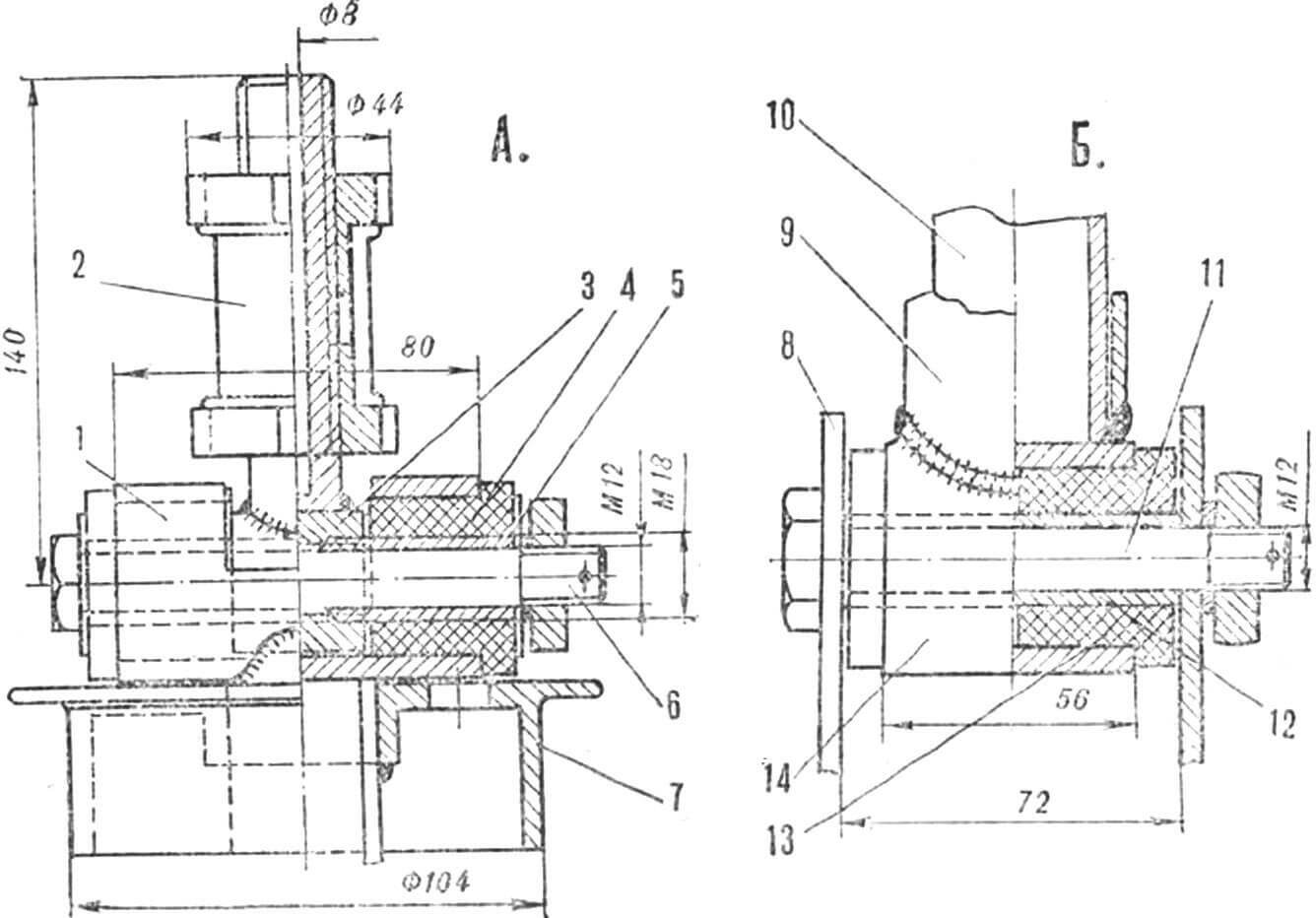
1 – clip, 2 – clearance adjustment mechanism, 3 – support clutch, 4 – rubber bushing, 5 – spacer sleeve, 6 – coupling bolt, 7 – spring cup, 8 – balancer post, 9 – support stocking, 10 – movable pipe, 11 — pinch bolt, 12 — spacer sleeve, 13 — rubber bushing, 14 — lower race of the rear strut.
The speedometer drive is from the main gear drive shaft, the gearbox is from the T-200L1 scooter. It is mounted on a bracket that fixes the main gear on the car frame, and is connected by a flexible shaft to the same gearbox, fixed in the socket of the front cross member of the frame. Next, using a flexible shaft (from the M-105 motorcycle), the rotation is transmitted to the speedometer.
On the instrument panel there is a speedometer in a block with a fuel level indicator and warning lamps (from ZAZ-968), a cylinder head temperature indicator, and an AP-110 ammeter. The remaining devices – the ignition switch, the windshield wiper and lamp switch, the central switch P-300, the starter switch VK-322 – are mounted on an additional panel located below the main one, to the right of the steering column. The tear from it is the switch for high and low beam headlights P-19A2. On the steering column bracket there is a P-20A2 turn signal switch. On the floor of the body there are clutch, gas and brake pedals, as well as gear and reverse levers.
Separate SEATS . The frames are from a motorized stroller, but the leaf springs in them have been replaced with rubber bands cut from an old car inner tube. The tapes are attached to the frame with hooks made of three-millimeter steel wire. Upholstery – mats made of porous rubber and artificial leather. The seats are fixed to the floor with metal brackets.
The ENGINE is located in front of the main gear in the space between the middle and rear cross members of the frame with the cylinder forward along the stroke. It is attached to the frame with four rubber pads from ZAZ-968 using homemade intermediate supports. The engine is started using an ST-366 electric starter or a kickstarter with a redesigned lever. To reduce exhaust noise, the car is equipped with mufflers from the Izh-P-3 motorcycle, for which the exhaust pipes had to be modified.
The main gear is from the TG-200 cargo scooter. It is secured to the frame with four M8 bolts. To protect against damage from below, a steel sheet 3 mm thick is fastened with the same bolts.
ELECTRICAL EQUIPMENT twelve volt. The G-108M generator is mounted on the engine in a standard way, as on the SZD motorized wheelchair. The relay-regulator RR-24G2 is installed on the right rear mudguard. The ignition coil is located in the engine compartment on the rear wall of the cabin. The ST-45 battery is located in the rear trunk to the right of the engine.
Recommend to read
 “SCHOOL” ON THE LUNGE
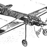
Said to be good the model airplane itself teaches us to govern ourselves. Especially valuable is her property for beginners korovikov. However, apart from flight, training models...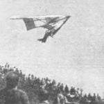 GLIDER WITHOUT SECRETS
"Fly higher, farther, faster!" This aircraft is the slogan became the motto of hang gliders. In our picture the glider master of sports M. B. Gokhberg. The front part of the dome is...
