The idea of creating a mechanical assistant for garden cultivation came to me a long time ago. I looked through relevant issues of the “Modelist-Constructor” magazine with descriptions of soil-cultivating tools and concluded that, based on the available power unit and the control levers from the Electron motor scooter, it would be better to make a motor winch.
For the 5.5 kW (7.5 hp) engine, I modified the ignition: instead of the generator, I installed a magneto, attaching it to the cooling fan housing. The drive comes from the impeller. I knew that such an ignition system is more reliable in operation and easier to maintain.
The torque from the power unit is transmitted to a drum with a wound cable, at the end of which a plow is attached. The transmission is chain-driven, and I took the parts for it from decommissioned agricultural machines. The drive sprocket (z1, on the output shaft of the power unit) has 14 teeth, and the driven sprocket (z2, on the drum) has 45 teeth. The roller chain is PR-15.875. The drum diameter for the cable is 180 mm.
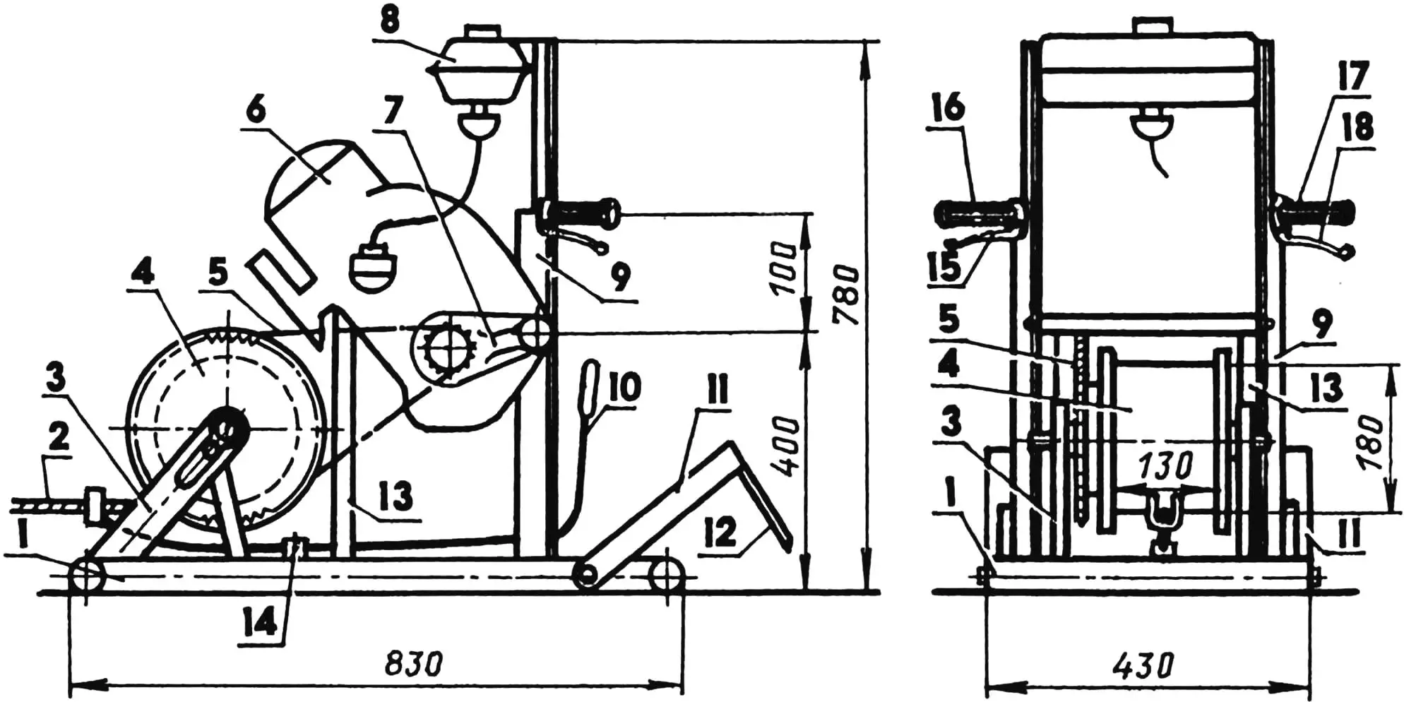
1 — base (steel water and gas pipe 33.5×3.25); 2 — cable; 3 — posts with adjustable struts; 4 — drum (assembled on an axle with two radial bearings 80204); 5 — chain transmission (z1 = 14, z2 = 45, chain PR-15.875); 6 — power unit of the Electron scooter (not shown in the front view); 7 — suspension; 8 — fuel tank; 9 — engine frame (steel angle 35×35); 10 — cable guide lever; 11 — anchor (steel angle 50×32); 12 — anchor spikes (shovels, 2 pcs.); 13 — stops (steel angle 45×45, 2 pcs.); 14 — cable guide hinge; 15 — gear shift lever; 16 — throttle control twist grip; 17 — control handle; 18 — clutch lever
The design turned out to be compact, with a total weight of just 60 kg. I transport it from the city to the garden plot in a Moskvich car. I put the winch on the back seat, while the plow-cultivator and the detached control handle go into the trunk.
I am satisfied with my motor assistant: it allows not only plowing but also planting, hilling potatoes, and cultivating beds. The winch is secured in place by a rotating anchor with two welded spikes.
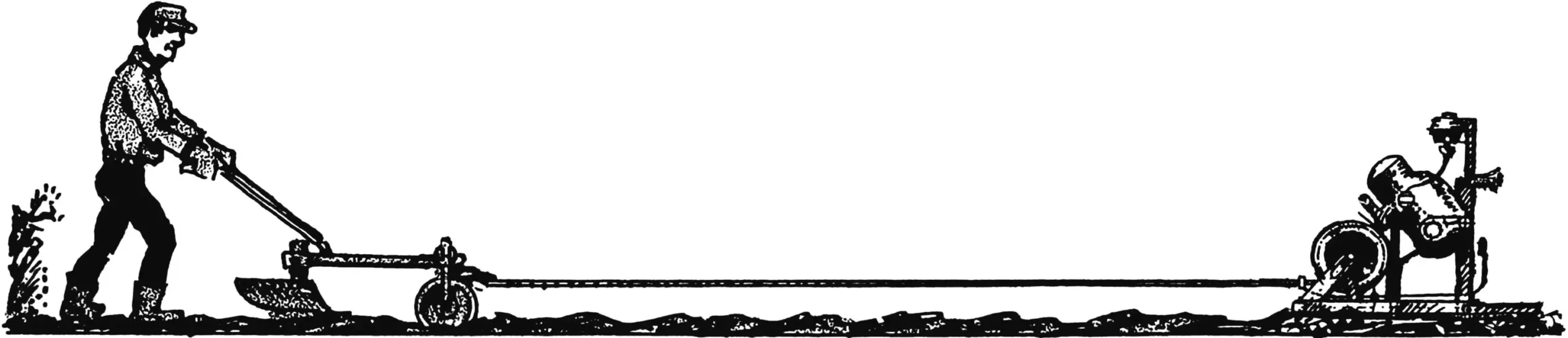
During operation, the winch easily pulls the plow-cultivator attached to the cable. The working speed of the soil tool is about the same as a person walking calmly. However, for each new pass, the plow must be rolled back to the start of the furrow manually, and the winch must be moved across the field. Still, the work goes quickly, since there are two of us: while one operates the winch, the assistant has time to drag the plow to the start of the next furrow.
Now for the design features. The base of the winch is welded from a steel pipe with an outer diameter of 33.5 mm. Attached to the base is an engine frame made of a 35×35 mm steel angle with the scooter power unit. To eliminate unwanted bending torque (from the tension of the chain drive), additional supports were added to the load-bearing structure of the winch.
The drum posts are also attached to the base, each with a bearing assembly and an adjustable strut, which also serves as part of the chain tensioning mechanism (together with a special device in the rear suspension of the power unit).
The rotating anchor, which is embedded into the ground, is a U-shaped frame made of 45×45 mm steel angle with two welded spikes. The anchor is connected to the winch base with bolts in a hinged joint. The spikes are made from ordinary steel shovels. When installing the winch in the desired location, the assistant steps on the crossbar of the U-shaped frame, driving the spikes into the ground, which provides reliable soil grip.
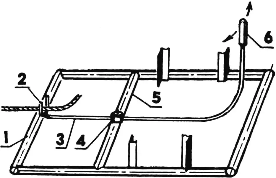
1 — winch base; 2 — fork; 3 — lever (steel water and gas pipe 21.25×2.75; lever arm length adjusted on site); 4 — hinge; 5 — crossbar (steel water and gas pipe 33.5×3.25); 6 — handle
The cable guide ensures even winding of the cable onto the drum. It also acts as a limiter, preventing the winding from slipping off. A crossbar is attached to the winch base, with the cable guide lever hinged to it. The lever has a fork for the cable and a handle. The length of the cable guide lever arms is such that the handle moves between the engine frame posts, while the fork with the cable moves between the drum cheeks.
The winch control levers are extended to handles on both sides of the engine frame. On the left — the clutch lever and the dynostarter button, on the right — the throttle grip, fuel mixture enricher lever, and the gear shift lever.
The design of the towed soil-cultivating implement is universal: the plow can be supplemented with a plow body, cultivator tools, and a hiller.
The most critical stage of the work is the first pass. After that, as they say, it’s a matter of technique: the plow will follow the line of the first furrow, guided by the furrow wheel.
The basis of this design is the beam from a decommissioned cultivator for continuous tillage. It has been shortened, and two guides have been welded to the front: one from a square-section pipe with an extendable furrow wheel axle fixed with two M18 screws, the other from a round-section pipe with an extendable field wheel axle. The 270 mm diameter wheels come from a decommissioned inter-row cultivator and are rubber-coated and self-cleaning.
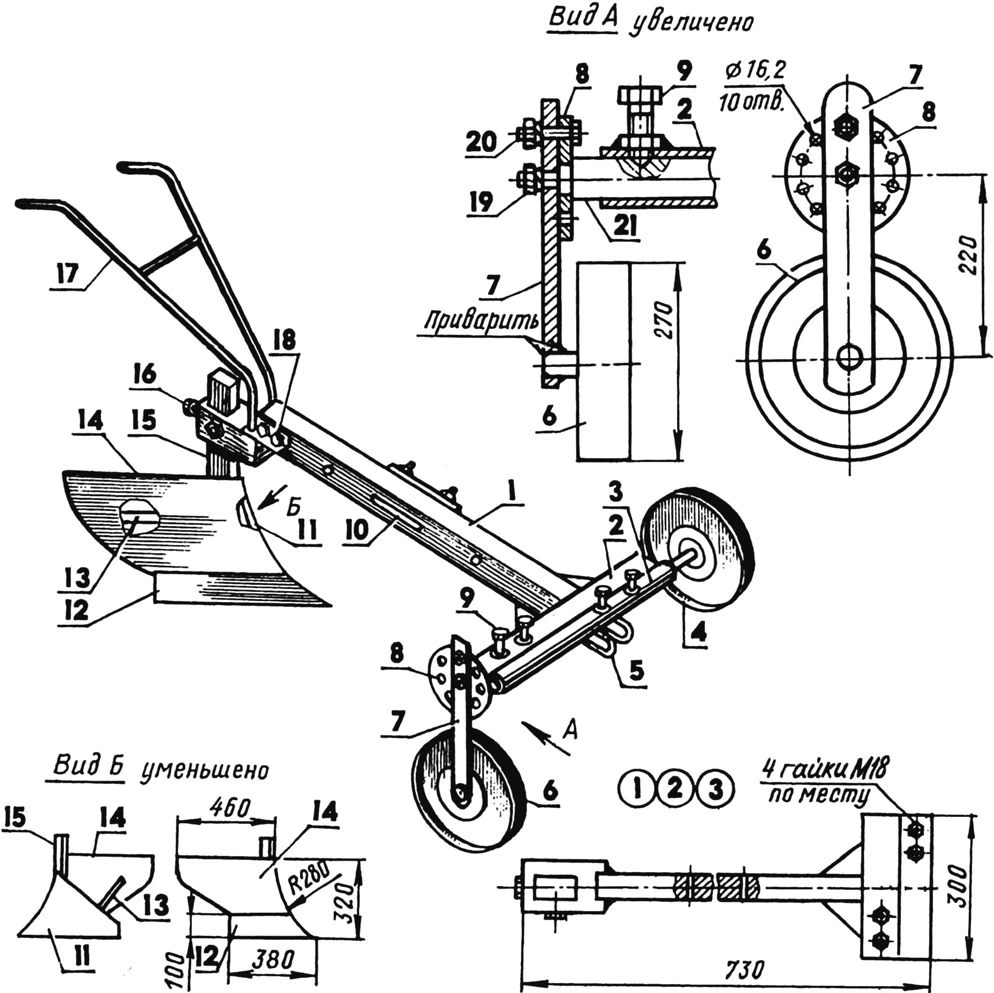
1 — beam (from a decommissioned cultivator, shortened); 2 — guide of the extendable support wheel axle (steel square-section pipe); 3 — guide of the field wheel axle (steel water and gas pipe); 4 — field wheel; 5 — central lug (2 pcs.); 6 — furrow wheel; 7 — wheel stand; 8 — depth regulator; 9 — M18 fixing screw (4 pcs.); 10 — clamp; 11 — field board; 12 — plowshare; 13 — spacer bar; 14 — moldboard; 15 — stand; 16 — M16 fixing screw (3 pcs.); 17 — handlebar (steel water and gas pipe 26.75×3.5); 18 — M12 bolt (2 pcs.); 19 — M16 nut; 20 — M14 bolt; 21 — extendable furrow wheel axle (hot-rolled square tool steel)
When converting the towed plow into a cultivator version, the plow body is replaced with a sweep, and razor shares are attached on both sides under the clamp. To achieve high clearance under the frame, a stand must be used. However, by extending the wheel axles from the frame, any spacing between the wheels can be set. During cultivation, the cable is attached to the central lug, and during plowing — to the side one. The plowing depth can also be adjusted by securing the body.
The body is copied from a well-proven horse plow. The moldboard is made of 3 mm steel sheet; the plowshare is cut from a blade, and the stand is made from a razor cultivator tine. The field board and spacer bar are made of 5 mm steel sheet.
Ready-made handles from the same single-furrow horse plow were used as the handlebar. However, a homemade welded structure from a steel water and gas pipe would also suffice. The fastening is at the rear of the beam with M14 bolts.
Like previously published analogs (see, for example, “Modelist-Constructor” No. 9’81, 3’89, 6’90, 4’94, 2’95, 8’95, and 1’97), my winch has advantages over conventional walk-behind tractors. It is simpler, more reliable, and more versatile. Most importantly, it makes it possible to cultivate the garden directly from the fence, without leaving turning strips. And it doesn’t compact the soil. In an hour, such a motor winch can plow five hundred square meters, consuming less than one liter of gasoline.
A. Negreev
Recommend to read
 GARDENER’S SAUNA
In a small utility block on my garden plot, I had a storage room measuring only 2.2x2.7 m. One hot day, the idea came to convert it into a mini sauna and also add a shower section. I... AKVAPLAN CO2
When it's rainy or cold weather and hold races racing gliders with the engine or rubber motor there is no opportunity, there comes a time of some discouragement. However, if there is...
