Fig. 5. Steering Assembly :
1 toothed washer, 2 — strip, 3 — mounting bolt 4 — pipe
The ratio of petrol and oil in it 20 : 1. Slightly increased the oil content in the mixture is quite acceptable for two-stroke engines. Coupled with good cooling, this allows the Clock to run in the August heat without overheating the engine.
And now about the design of individual components and parts of metafrasi about how and what they are made. Let’s start with the frame. Both Shaki her cut from steel sheet of thickness 4 mm. Rectangular viewing window done only on the left of them. Then both cheeks baited — connected multiple point welding with encircling band, and then processed together. Openings with specified dimensions, machined with a boring tool.
Fig. 6. Remote bushing :
1 — pin. 2 — remote handset. 3 — strap.
The upper and lower rings of the bearing assemblies are welded to the corresponding holes using the guide washers and the mounting studs M18. One set is designed for mounting lower rings, one for the top. Once cooled the welds, studs, And washers were removed, the edges of the holes machined sharpened triangular Faber to the bearing housings freely have their place. Gap between them of the order of 0.10—0.12 mm. this Operation is time-consuming and required special care.
All rings are cut with a gas burner of sheet steel 8 mm thick and machined on a lathe. Bolt holes drilled in them before welding, and then is threaded. Moreover, the housing upper bearings with their rings reamed simultaneously to ensure alignment of all 24 holes. Bolts М8х20 entered into them freely and easily are screwed. All they Needed 24 pieces.
Fig. 7. Drill holes for the pins :
1 — push, 2 — remote handset, 3 — conductor. 4 — stud.
Welding frame. The rings of the upper bearing assemblies are mounted in the same way as the bottom, with the only difference that the mounting sleeve is kept not one internal, two external pins and two U-shaped profiles, since the housing of the left bearing had no Central hole.
All stud two upper and one lower) are tightened to failure, cheek belted stripe steel, of a width 34 and a thickness of 5 mm and connected by spot welding with a step of 50 mm for its entire length. Then began the final Assembly of the frame, and after applying the seam with a length of 60-80 mm, the welding is interrupted and a similar seam superimposed on the opposite side of cheeks. This is done to ensure that all the frame has not warped and the labor is not in vain.
After the metal Ostap, sepici and bolts were unscrewed, and the bearing housings are removed. But not before because when welding the holes in the rings under them were deformed, and then again it would take subranie.
Mounting sleeve (about the bearing) is used when assembling the frame in order to obtain full alignment of bearing shells as the lower Valo-gears, and upper. Without them, the cheeks of the frame when welding warp — twist.
The end surface and outer diameters of the bushings are machined in a single setup in the spindle of a lathe wall right and left incisors. Therefore, for the lower bushing in advance in a thick-walled pipe welded two straps with
sretraline holes d of 16.1 mm. From precision machining about buildings to a large extent depended on the quality of the frame.
Next to the box was welded a cross bracket and support the engine mount. The notches in the bracket done finger cutter d 10 mm. Bearing is welded from strips of steel 30X4 mm.
Cover the viewing window is cut from steel sheet of thickness 2 mm and Attached to the frame with four bolts М4Х6, seal with sealant — it can be removed once a year to check the status of the main chain.
In the last turn welded to two steel cube with a side of 10 mm | mm from the upper edge of the main square. They are drilled and tapped for screws М6х6 cover through which skipped the main goal and
About the main Valo-toothed wheel. It is of steel 40X with subsequent heat treatment. The teeth are in number of 15 pieces — with the same step n in main chain (19,05 mm). You can use ready gear if I can find the right.
The holes in the ends of the Valo-toothed wheel d 7.5 mm drilled with the use of a conductor. It does need to used when making a remote mounting from all parts of metafrasi are subjected to the greatest loads. All openings d 7.5 mm drill with one sharpening of the drill. When drilling remained a center marking points below the pins, one bushing freely entered into holes of the other. The ends of the sleeves are perpendicular to their longitudinal axes.
When planting pins used fixture the gasket. The depth of the center hole in it to exactly 12 mm — this is especially important during installation. The device is not quenched.
It is also important that the tolerance on the left side pins designed within the specified limits.
Strap distance sleeves (six PCs) of steel 3 thickness: 5 mm Hole, the distance between which is 73 mm, drilled to the tolerances specified in the drawing. Otherwise it would be impossible to achieve interchangeability of blade cutters.
The Assembly sequence of each spacer sleeves as follows: first was pressed on the pins of the left ends. Then welded a strip of 10 mm from the edge of the sleeve and only then drilled holes in the right side.
Bracket engine mount is made of steel strip 30X10 mm. All dimensions are designed for sure: the axis of the holes had to cope with the axes of the welded nuts.
The muffler made from a cut length of about 200 mm from the body of the muffler of the motorcycle “Balkan-50”. Doña his cut from steel sheet of thickness 1 mm. Remote partition |of the same thickness and diameter by 9 mm smaller than the inner diameter of the housing of the muffler) riveted to the bottom outlet three special rods arranged at an angle 120° to each other. And only then welded a bottom in the housing of the gas go-turnip. With this silencer the noise motores no more than a chainsaw “Friendship 4”.
Material hub gears — steel 45. Axle top Valo-toothed wheel is firmly in the hole of the hub. The radial runout of the hole d 28 mm and 60 mm and lateral runout of the front surface-side d 60 mm is minimal as the author worked them on a lathe for a single installation; hole ø 8 mm drilled simultaneously with hole-
STEMI in a large toothed wheel with 45 teeth.
Fig. 8. Fixture-gasket .
The upper bearing soaked cast iron. In them is hidden one of the tricks of construction: the bearing seats machined with a 10-millimetrovykh offset relative to the Central axis that allows you to adjust the chain tension.
Here it is necessary to pay attention to the following points: for the most accurate alignment of the axes of the holes in the housings and the same precise drilling 24 holes in the top rings of the box frame. It was necessary that the bearing housings could be installed in increments of 15° in the circumferential direction (to change the tension of the primary chain).
The material of the Valo-toothed wheels steel 40X. The wheel is heat treated by the method of quenching in oil when heated to 633° and tempering to HRC = 45 to 47.
Top prosipa frame consists of a sleeve (steel 45), the strips 20 x 6 mm and the ribs of steel sheet of thickness 4 mm. When connecting the eyelets to the frame is necessary to remember that the axis of the hole d 18 mm must be perpendicular to the horizontal traverse.
All the details of the back support is made of steel 45 with the exception of the axis, which is made of steel grade X12 or 35HGS followed by heat treatment.
The original part of the steering wheel — two lock washers, three pipes thick power lines-inches and the strap 30 X 30 mm Mounting bolt M12, shown, used for welding one of the washers with a strap. The second washer is welded to the corner bracket, vyfrezerovkami from a piece of steel 45. Welding is carried out using the same mounting bolt.
United М12Х65 bolt, washer and included engagement with each other and allow you to adjust the handlebar height depending on the height of the operator.
Recommend to read “DISAPPEARING” STAIRS A lot of trouble delivers the design of internal stairs, for example, the attic. For convenient large marches, as a rule, not enough space and they are very steep, which is dangerous,... Underground water tower Having a year-round water supply system — and especially an automatic one — in a rural-type home is the dream of any homeowner who does not yet have one. Of course, few of them are willing... 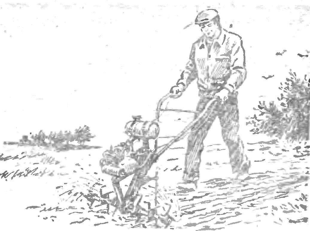
 His first motomizu A. Migranov built in 1981. As a prototype use if they had allowed themselves the development of his friend Peter Koynova. Although much was done differently: the engine mount, rudder, installation of bearings, three-stage gear transmission and cetera.