A ride on the slug even with the comfort of no one wanted. Besides, on busy streets velomobiles represented a serious obstacle to regular city transport. For this reason, enthusiasts interest in recumbent faded.
However, the engineers of the American company “General dynamics” in those same years designed and built a recumbent with an aerodynamic fairing with a total weight of just 23 kg. In the record-in the 200m he reached the speed of 95 km/h And 80 km/h could develop it even velosports average.
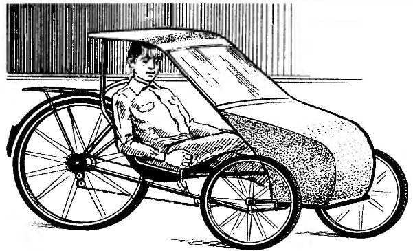
Recumbent with a plastic fairing
Like the recumbent, however, a bit heavier, designed and built in the Minsk Palace of children and youth. The photos show the first specimen, weighing 32 kg with cabin (fairing) and 22 kg without cabin. The second sample, shown in the figures, is made subject to the shortcomings of its predecessor identified in the test races. Thus, in particular, the rear wheel with steel rim (road bike) was replaced by easier — with aluminium rim and multi-speed sleeve (sports bike). In addition, the large front wheels complicates the management, so they were replaced by the smaller wheel size 20′. Undergone innovations and the cabin is polystyrene it has given way to more lightweight materials: fiberglass and plexiglass. All this together significantly reduced the weight of the car will increase its speed with the same energy consumption of the driver.
The velomobile has a transmission with the intermediate reduction gear and two modes of steering: conventional steering column and steering wheel… seat. The last option and is presented to the readers.
Here is how our recumbent.
Frame of the velomobile:
1 – the case of the carriage (road bike); 2-bearing podkorytova (pipe 25×1,5); 3—holder (pipe 18×1,5); 4 — pivot bushings (pipe 18×1,5); 5 — seat frame (tube 20×1,5); 6 yoke of the steering column; 7 — bearing seat post (tube 20×1,5); 8 – lugs (off road bike); 9 – jumper (pipe 20×1,5); 10 — spars (pipe 20×1,5); 11 — mounting bracket of the intermediate gear (area 35x35x3 and strip 26×3); 12 — rack (tube 20x 1.5 m); 13 – cross member (tube 25×1,5)
Its frame is welded from thin-wall steel pipes. Ahead it has a housing in which is mounted a standard carriage road bike. Its sprocket chain connects with a homemade intermediate gear, located under the driver seat. The reducer is mounted in special brackets, welded to the frame rails. Another chain connects to multi-speed gear sleeve rear wheel fixed in the ferrules, also taken from a road bike.
A more sophisticated aspect of the frame — the steering column. It is taken from a road bike and shortened to the required length. As the intermediate gear, the column is placed under the driver’s seat — on the plate that is welded to the frame rails.
The very same seat is made of leatherette, a tent or, better mesh — the driver is comfortable. Cloth worn on the frame and rear cinches with a drawstring.
To install cockpit (fairing) and front wheel frame includes a cross tube, the ends of which have pivot bushings.
The frame is welded in the simplest slipway, and it is then cooled, to avoid thermal leashes (deformation) of the whole structure. Then thoroughly cleaned from scale and rust, degreased, coated with primer and painted with three coats of bright automotive enamels.
Transmission. As the carriage is over the standard velomobile, a description of its device can be omitted. We will stop better on design improvised staging (and lowering) of the gearbox. It consists of horizontal axis, around which rotates in bearings steel-
tion hub with two sprockets from the rear wheels of different bicycles. The number of teeth they have 15 and 19.
Intermediate gearbox:
1 —axis (bolt M12x1,5, L100); 2,13 — brackets of the frame of the recumbent; 3,9,12 — sleeve remote (pipe 15×1,5, L1,5, L12, L31); 4,11 — bearings 101; 5 — hub (steel 40X); 6 — asterisk input (z = 15, from the bike); 7 — spacer (pipe 39×1,5); 8 — asterisk output (z = 19, from the bike); 10 — retainer ring (20 MN 470-61); 14 — nut M 12×1,5.
Steering:
1 — unit rotary; 2 — thrust of the cross (pipe 10×1,5); 3 — rocking chair (steel, sheet s2,5); 4 — bracket rockers (steel, sheet s2); 5 — pull longitudinal (pipe 10×1,5); 6 — the wheel (off the bike); 7 — bolts M5 (6 pieces).
The left rotary module (right — mirrored):
1 — pins (steel 40KHN2MA); 2 — wheel axle (steel 40XII2MA); 3 — plow power steering (steel, sheet s2,5); 4 — bushing pivot; 5 — sleeve bearings (bronze, PTFE allowed); 6 — nut M10; 7 — pin; 8 — nut M 12×1,25; 9 — M4 screws (2 PCs.)
The sprocket engages with the hub by its three projections arranged at an angle of 120°. There are many ways to perform in the hub of the response slots for these projections. We have used the following. Protocel seats for bearings and locking rings, drilled in the right side of the workpiece hub at an angle of 120° three holes of 6 mm in diameter. Then clamped the workpiece in the Chuck of the lathe and Stoch its cylindrical surface to a diameter of 36 mm corresponding to the landing places of stars. The remaining three blind holes of the hollows is the return grooves. After machining, the finished hub was hardened to HRC 48…50.
 In the late 70-ies in the press, especially in the journal “modelist-Konstruktor”, wrote a lot about velomobiles. Was presented designs of various authors. Some argued that a new form of transport, which in the future will press not only a bike but a car. However, nothing happened. Why? A simple answer to this question is difficult. Will only Express some thoughts.