
Having a year-round water supply system — and especially an automatic one — in a rural-type home is the dream of any homeowner who does not yet have one. Of course, few of them are willing to build a water tower for this purpose and drill a deep artesian well. And there is no need for that nowadays — other systems have been created, and they are quite compact and available in various capacities.
Such water supply systems, manufactured, say, in Italy or Spain, are sold in all cities and even in large settlements. However, their price is above average (by which I mean the purchasing power of middle-class people, which the vast majority of Russians still cannot even approach).
But a shortage of money cannot make a skilled craftsman give up the equipment needed in the household; it only prompts him to create it with his own hands, while also forcing him to devise the machine’s design — after all, no one will let you take one apart in a store for that purpose.
That is how life forced me to build an automatic water supply system for my house and homestead plot with all its outbuildings with my own hands.
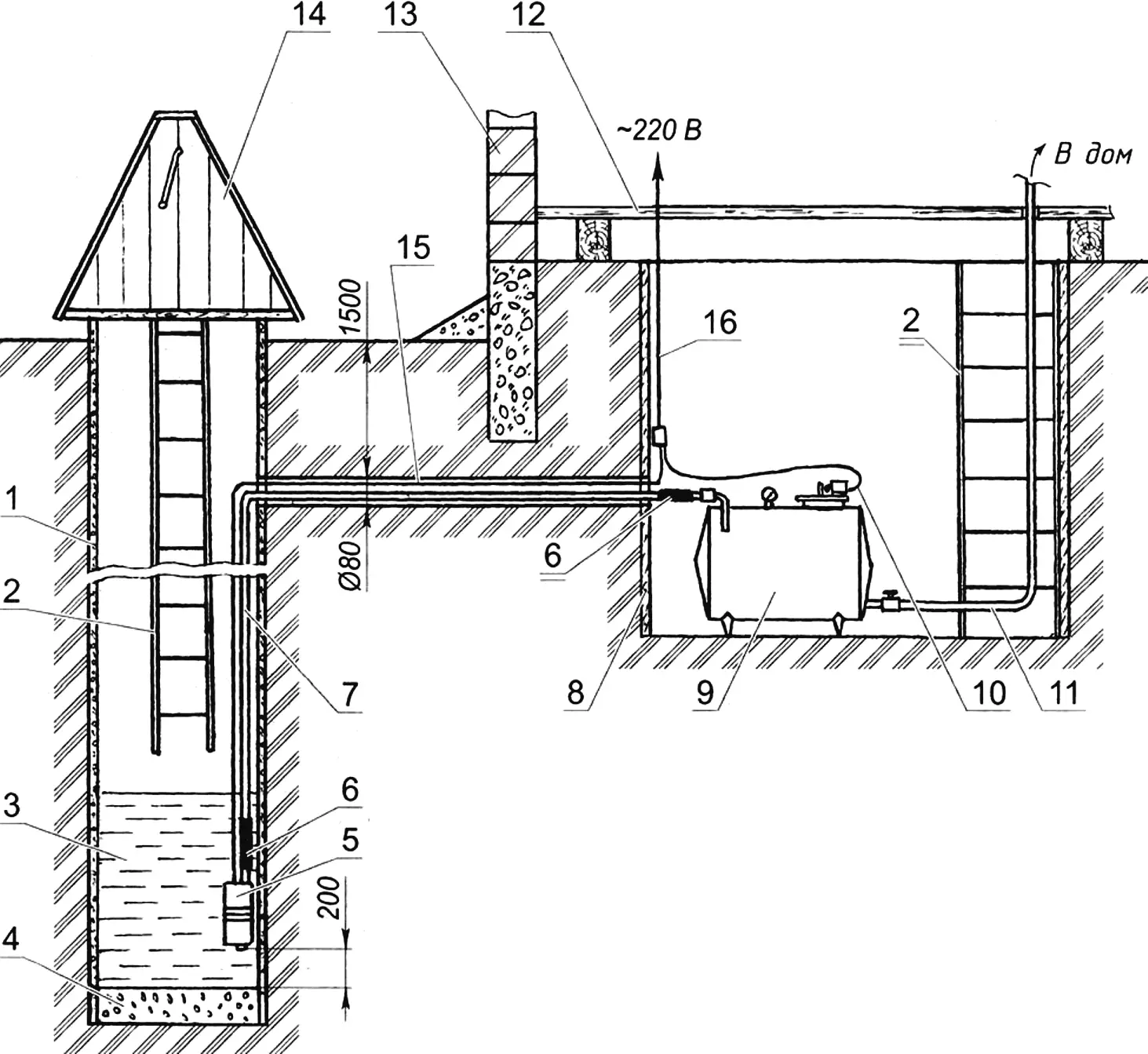
1 — well shaft (concrete rings Sh1000); 2 — ladder (steel angle 25×25, 2 pcs.); 3 — water; 4 — stone fill; 5 — submersible pump (vibratory type); 6 — coupling (rubber hose, 2 pcs.); 7 — supply pipe (1/2″); 8 — basement wall (concrete); 9 — water pressure unit; 10 — limit switch wiring; 11 — water supply to the house (1/2″ pipe); 12 — floor; 13 — house wall; 14 — insulated well house, board with insulation; 15 — pump cable (2-core, waterproof); 16 — household mains cable
It consists of two main parts: the water source and the pressure unit.
The basis of the water supply system is, of course, the source — a well with a shaft made of reinforced concrete rings 1 m in diameter. I built it long ago, but I drew water with a bucket, using the pump only in summer to water plants.
The depth of the well is not especially important — all modern household submersible pumps can lift water from depths of up to 50 m — but it must reach the water-bearing layer (and not just groundwater). However, the volume (reserve) of water in the well must be greater than the capacity of the pressure tank — because the yield (inflow of water) into the well may be less than the pump’s output. Submersible pumps cannot run “dry” — they will inevitably burn out, since the pumped water also serves as their cooling fluid.
If the system fails, the well can still be used in the traditional manual mode, lifting water with a gate, drum, and rope and bucket. But that has not happened to me in three years of operating the system. Power outages did occur from time to time, though.
A small house is built over the well, the neck is always closed with a lid, and in “cold winter weather” I insulate the above-ground part of the shaft with old quilted jackets.
Water is drawn from the well by a household submersible vibratory pump “Malysh” (similar pumps can also be used: “Rodnichok”, “Agidel”, and others). The pump is lowered into the shaft (and into the water) almost to its full depth, but stops 200 — 300 mm above the bottom so that settled suspended particles are not drawn in.
The pump’s outlet pipe is connected to the supply (pump) pipe with a 1/2″ bore through a rubber hose coupling (to damp vibration). The coupling is secured to the pipe and the hose with clamps. The supply pipe exits through the well shaft wall and runs underground below the maximum soil freezing depth to the flow-and-storage pressure tank located in the house basement and forming the basis of the water pressure unit. A waterproof power cable for the pump is laid alongside the pipe.
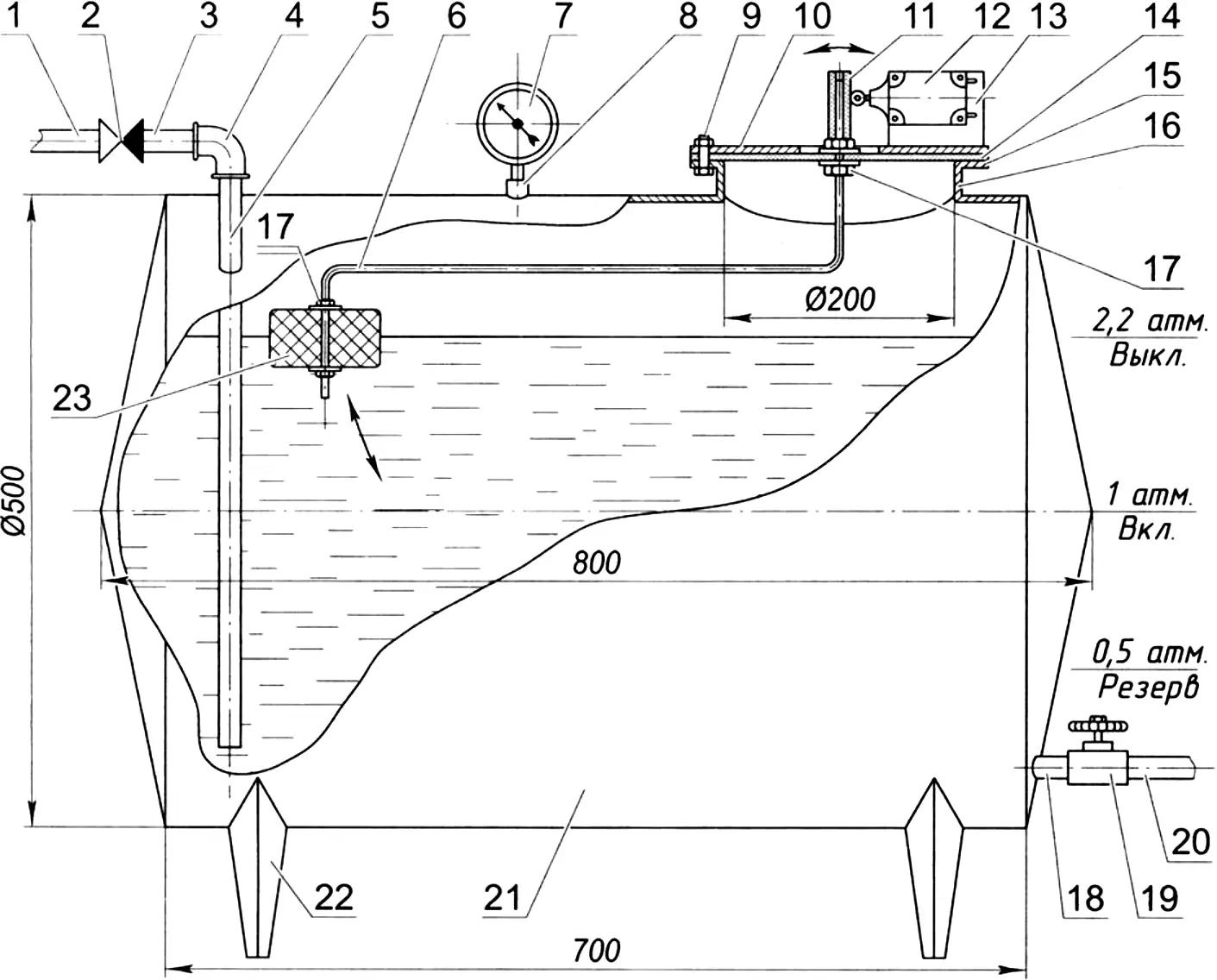
1 — supply pipe; 2 — check valve; 3 — union; 4 — elbow; 5 — inlet; 6 — lever; 7 — pressure gauge; 8 — threaded nipple (coupling); 9 — lid fastening to flange (M8 bolt, 8 pcs.); 10 — lid (steel sheet s3); 11 — lever tip (rubber tube); 12 — limit switch (VPK 1211); 13 — limit switch mounting bracket plate (steel sheet s3); 14 — diaphragm (reinforced rubber, s7); 15 — flange; 16 — neck; 17 — M10 nut and washer for fastening lever to diaphragm and float to lever (4 sets); 18 — outlet pipe; 19 — valve; 20 — water outlet to the house; 21 — flow-and-storage tank (stainless steel, sheet s2); 22 — tank leg (stainless steel, sheet s2, 4 pcs.); 23 — float (PVC)
The supply pipe is connected to the tank inlet (also a 1/2″ pipe) through a shut-off check valve and another hose coupling. The inlet pipe itself is lowered into the tank almost to the bottom.
The tank is placed, as mentioned, in the house basement. In my case, the basement is also sunk more than two meters deep, since it also serves as a root cellar. But that is not necessary at all — there is always a positive temperature under a heated residential house.
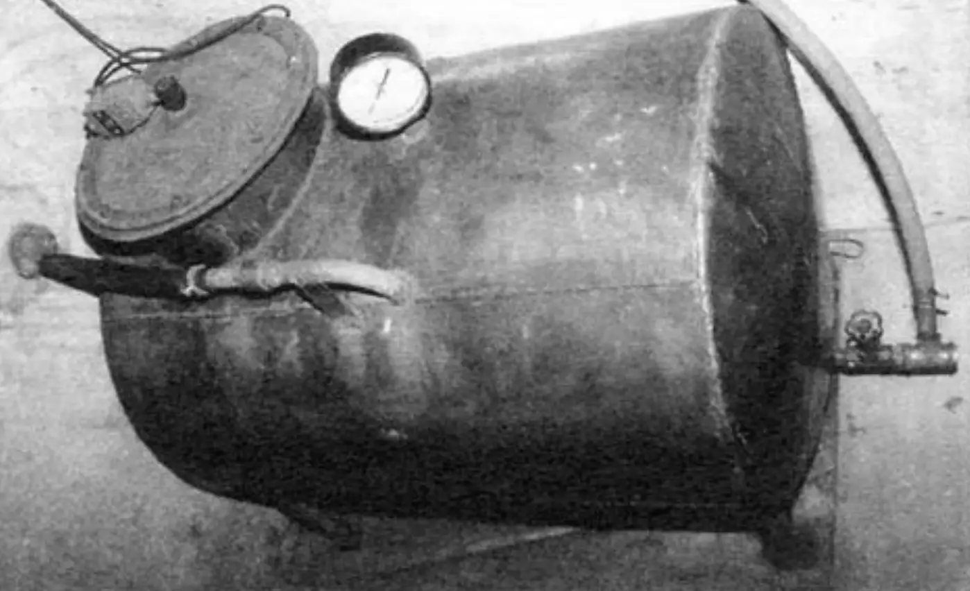
The tank is cylindrical and welded from 2 mm blackened stainless steel sheet. It stands on welded legs on a steel sheet underneath, because although the basement floor is concrete, it is thin. The tank capacity is about 150 L. The larger its volume, the less often the limit switch will operate, and therefore the less often the pump will start. Practice shows that the service life of electrical appliances and devices (including deep-well pumps) is inversely related to the number of their on-off cycles.
A VPK1211 limit switch is installed on the tank neck lid. It is actuated by a lever with a PVC float (similar to the one in a toilet tank). The lever is also mounted in the tank neck, but only on a 7 mm reinforced rubber diaphragm. The end of the lever exits outside through a central hole in the lid, and a rubber tube is fitted over it.
An outlet pipe fitting is cut into and welded to the tank side wall near its bottom; a discharge pipe connected through a valve supplies water to the house and other utility rooms. The nominal bore of the pipe, fitting, and valve is 1/2″.
The system works as follows. The interaction of the lever and float is adjusted so that when water is drawn from the tank down to half full, the lever tip no longer acts on the limit switch. The electrical circuit powering the pump closes — and the pump begins pumping water until most of the tank volume is filled. At the same time, the pressure of the air in the tank increases to 2 — 2.2 atmospheres, the float rises, and the end of the lever actuates the limit switch, which opens the electrical circuit and stops the pump.
Water draw-off also proceeds automatically. When a tap is opened in the house or a utility room, water under the pressure of the air inside the tank rises and flows to the consumer. When water use reduces the tank to half full, the pump starts again and replenishes the reserve in the tank.
In case of power failure to the pump, water can be drawn from the tank almost until it is completely empty — when the air pressure in the tank equals 0.5 atm. A check valve installed before the inlet pipe prevents water from flowing back from the tank into the well.
When the system is built with your own hands, its cost compared with a factory-made one drops by an order of magnitude while retaining the same consumer qualities.
The story about the water pressure unit could end here. But I should note that at first my pressure unit was different — as the flow-and-storage vessel I used a 40-liter milk flask left over from “collective farm” times. The drawback of a system with such a vessel was observed only when water consumption was high: the pump switched on and off frequently, which is undesirable. However, with low consumption this is even good: the water will not stagnate.
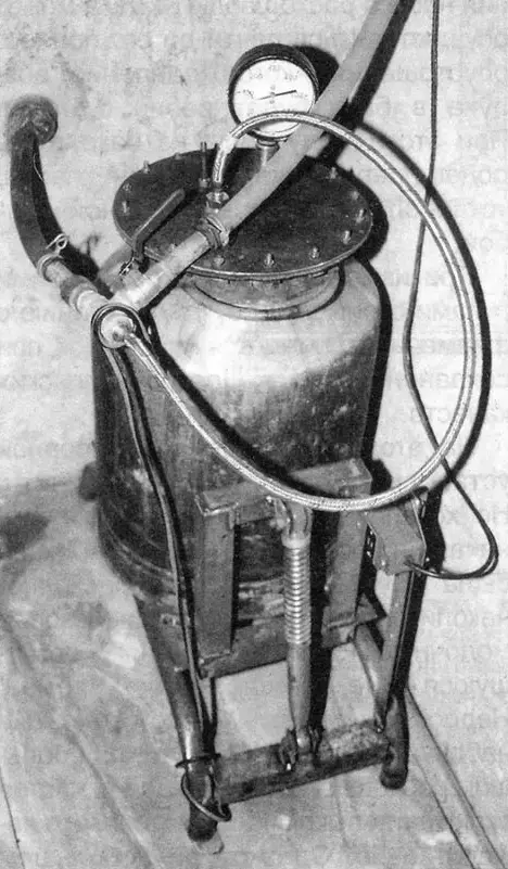
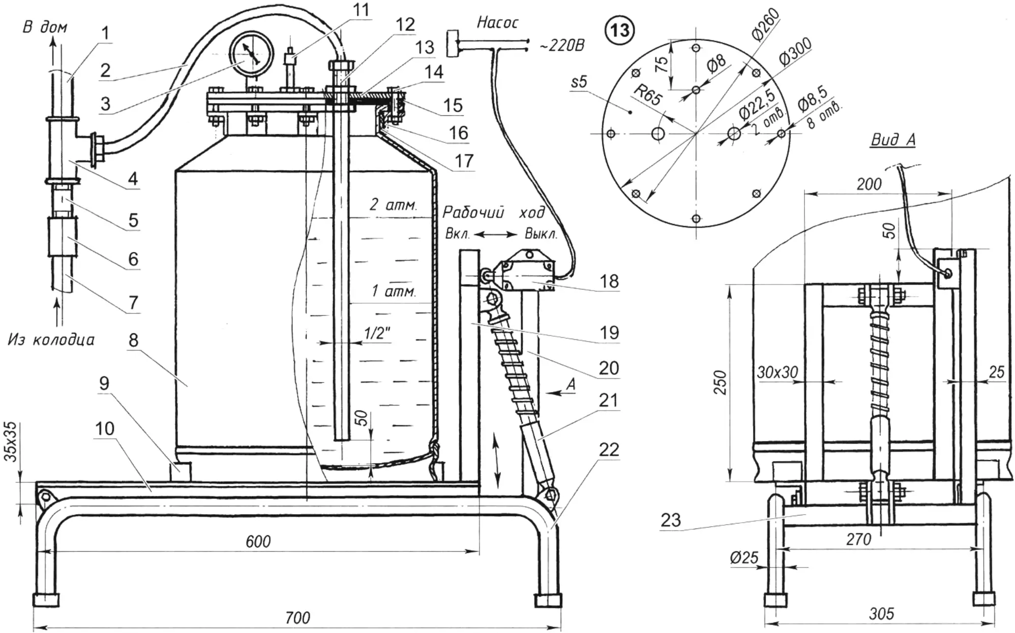
1 — water outlet to the house; 2 — supply hose; 3 — pressure gauge; 4 — tee; 5 — union; 6 — check valve; 7 — supply pipe; 8 — flow-and-storage vessel (40-liter flask); 9 — holder (2 pcs.); 10 — swinging frame (angle 35×35); 11 — nipple; 12 — inlet; 13 — lid (stainless steel, sheet s5); 14 — lid fastening (M8 bolt, 8 pcs.); 15 — gasket (rubber with fabric base, sheet s6); 16 — band clamp bracket (angle 30×30, 8 pcs.); 17 — band clamp (steel strip 30×3); 18 — limit switch; 19 — portal (angle 30×30); 20 — limit switch post (angle 25×25); 21 — shock absorber (from a moped); 22 — frame side member (pipe Sh25, 2 pcs.); 23 — frame cross member (angle 35×35, 2 pcs.)
I modified the flask. From the neck I removed the standard lid with its fastening elements and latch. I tightly wrapped the neck with a band clamp made of steel strip, welding its ends with an overlap. At equal intervals I welded eight brackets made of angle sections to the band clamp.
Next, from 5 mm stainless steel sheet I cut a new lid, placed it on the neck, and simultaneously drilled 8.5 mm holes in it and in the horizontal flanges of the brackets. I also drilled three holes in the lid — two 22.5 mm in diameter (one for the intake tube, the other for the pressure gauge) and one 8 mm in diameter (for a nipple to pressurize the system). For the lid I also made a ring gasket from 6 mm rubber-fabric sheet.
I mounted the flask on a swinging frame attached to a fixed frame on one side directly to it, and on the other through a shock absorber. To attach the upper end of the shock absorber I had to weld a portal to the swinging frame, which I used as the lever for the limit switch mounted on a separate post, also welded to the frame.
After installing the pressure gauge, nipple, and inlet tube, I tightly bolted the lid to the band-clamp brackets through the gasket with M8 bolts.
To determine the limit switch position on the post more accurately, I filled the flask two-thirds full with water — in this position the portal presses on the switch roller and opens the electrical circuit powering the pump.
The operating principle of the “flask” pressure system is no different from the “tank” one. It served me reliably until replacement for a year and a half.
Modelist-Konstruktor No. 9’2009, A. MATVEYCHUK
Recommend to read
 CULTIVATOR OF “EUREKA”
No doubt, the motor-plow or microtracker in the farm economy — assistant-all-trades. But where the plot-all small, and the garden trees and shrubs planted densely enough, the walk-behind... Double glazing and climbers
The glazing is firmly established in our life. Perhaps no modern buildings, no matter where they were installed. These Windows are made of high-strength glass, but this does not...
