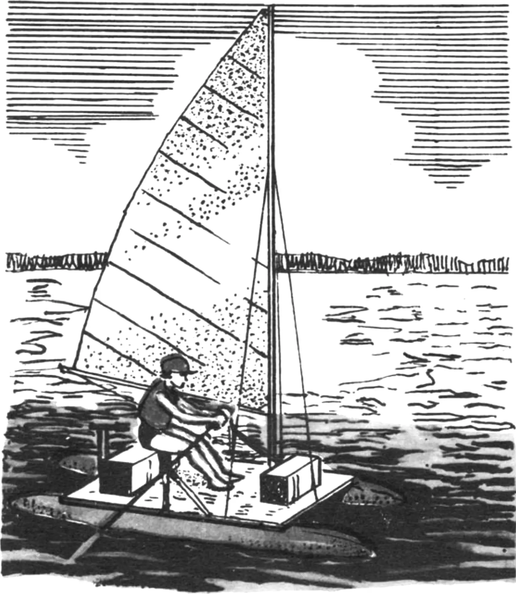
No sooner do rivers and lakes clear of ice than thousands upon thousands of water-tourism enthusiasts begin preparing for the new season. They take their “folders” and “inflatables” out of storerooms and garages, and bring yachts and boats out of winter storage.
Those who live near the water or have a car at their disposal know nothing of the problems that weigh on the “horseless” lover of water travel. How much can you carry on your back? Only a “folder” or an “inflatable.” And even then not alone, since even a tightly packed boat requires a separate porter. And then there is the tent, provisions…
What is a person who wants to be alone with nature to do? And not in a kayak or inflatable, but say, on a sailing catamaran? Look for a helper to get to the water? But then how do you get back — look for a helper again?
Many of these questions are resolved if you take advantage of the experience of D.A. VAKHLAMOV. He proposed an original design for the sailing catamaran «Tsarevna Lyagushka» (Princess Frog), which has two very important merits. First, it is made mainly of pine — a very common material. Which means that «Tsarevna Lyagushka» can be reproduced practically anywhere in our vast country. All it takes is the desire. Second, the catamaran is designed so that one person can quite well disassemble it, transport it, and assemble it. The deck of «Tsarevna Lyagushka» is fairly spacious: the crew of four “sailors” — the designer’s entire family — fits on it comfortably.
At the editors’ request, Dmitry Ananyevich described the construction of his catamaran.
The best memories of my childhood and youth are tied to quiet streams near Nizhny Novgorod, to the majestic lakes of the Southern Urals, and, of course, to the boat.
Looking at the hordes of “roaring” machines, I decided that even in urban conditions there must be a way out, since there are plenty of rivers and reservoirs around the city. But what to choose — a kayak? Sitting in one is uncomfortable, there is little room for touring gear, and you can only paddle on calm water; you won’t venture onto a reservoir in steep waves. An “inflatable”? You can cross an ocean in one. You can, but very slowly. A mast with a sail, centerboards, and a speed rudder will add capability, but capacity will drop significantly. A boat of duralumin sheets joined by rubberized fabric? Not serious: because of its size they won’t even let you into the subway. A “horseshoe” like the “Grif”? No argument — to each his own. Haul it on a car, drag a heavy motor and fuel cans on your back, enjoy the speed. Speed and the roar of a motor interfere with my communion with nature…
And then a friend advised me: a catamaran! I took his advice — and after a while a wooden frame, floats, mast, and sail appeared at my home.
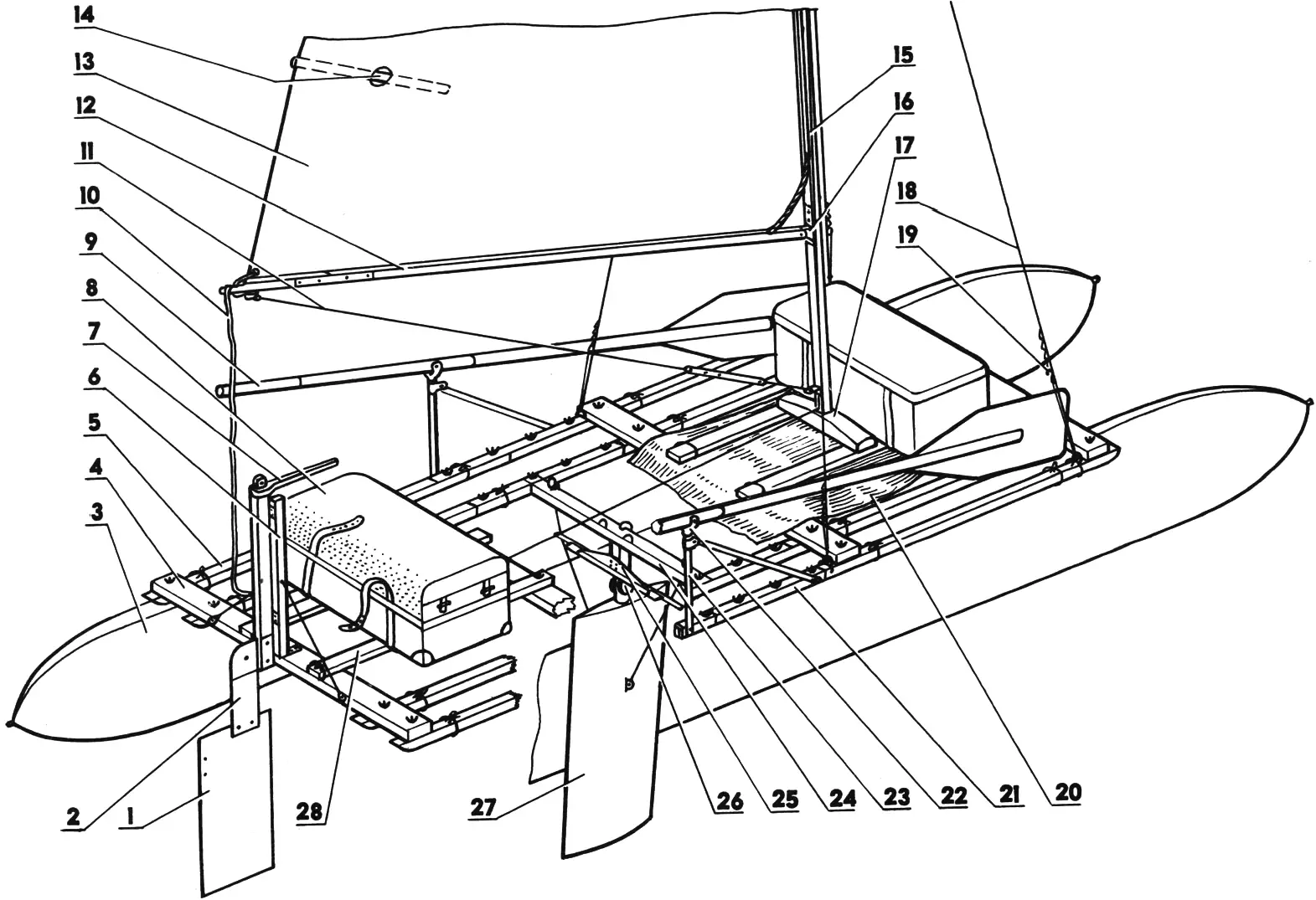
1 — rudder blade; 2 — gudgeon; 3 — float (2 pcs.); 4 — beam (4 pcs.); 5 — stringer (4 pcs.); 6 — rudder post; 7 — tiller; 8 — trunk (2 pcs.); 9 — oar (2 pcs.); 10 — boom sheet; 11 — boom vang; 12 — boom; 13 — sail; 14 — batten (4 pcs.); 15 — mast; 16 — boom swivel; 17 — mast step; 18 — shroud (4 pcs.); 19 — adjustable shroud tensioner (4 pcs.); 20 — deck; 21 — stringer connector (4 pcs.); 22 — oarlock (2 pcs.); 23 — outrigger oarlock (2 pcs.); 24 — centerboard beam; 25 — centerboard wire stretcher; 26 — centerboard pivot; 27 — centerboard; 28 — deck beam support (4 pcs.).
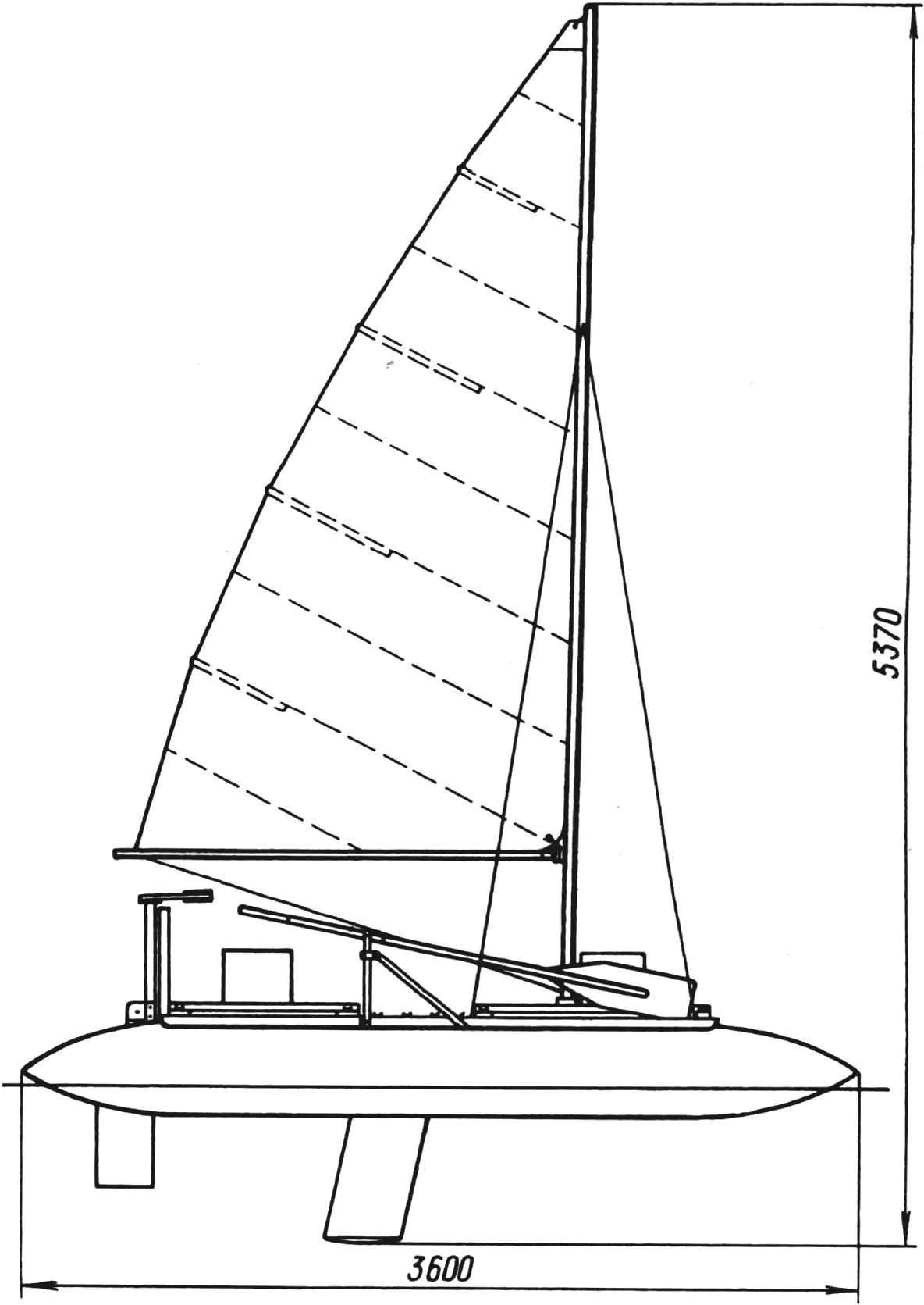
Assembled, the catamaran named «Tsarevna Lyagushka» is shown in Fig. 2. It is quite simple and extraordinarily interesting to handle. A sail of 4 m2 provides good speed in moderate wind and adequate safety in squalls. So you need not worry about your passengers. The “sailors” on the catamaran, for example, were my five-year-old child, my wife who suffers from aquaphobia, and my ninety-year-old father-in-law.
If you decide to build yourself a similar craft, you will not need any special carpentry or metalworking skills. But time, care, and diligence will be necessary.
Choose quality material. Pine is preferable: for its even grain without knots and its low specific weight. With sufficient strength and resilience. Wood aged several years in a dry place is desirable. Do not use green wood — it will surely warp and everything will be hopelessly ruined.
FRAME. It is advisable to start with it. The frame consists of four longitudinal timbers — stringers — and four transverse ones — beams. Stringers in one piece are too long and awkward to transport, so it is better to make them in two parts. The parts are of different lengths, since outrigger oarlocks are mounted on the connecting brackets at a distance convenient for the rower.
Carefully plane eight bars of 40×40 mm cross section, watching that there is no twist: four of them (1340 mm long) will be the bow sections of the stringers, four (1110 mm long) — the stern sections.
Prepare four duralumin angle brackets 40x40x4 mm, 500 mm long.
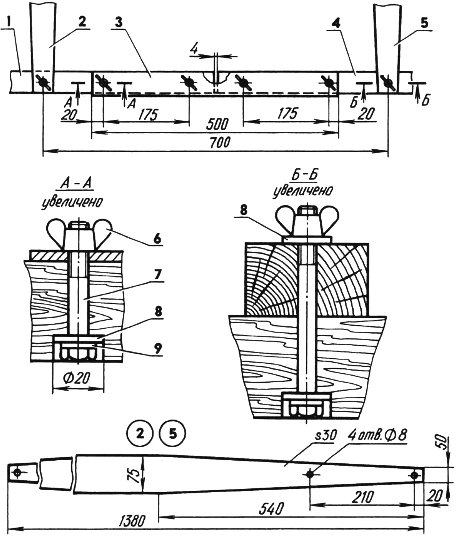
1 — stringer part, stern (pine bar 40×40, L1110); 2,5 — beams (pine bar 75×30, L1380); 3 — connector (duralumin angle 40x40x4, L500); 4 — stringer part, bow (pine bar 40×40, L1340); 6 — wing nut M8; 7 — bolt M8; 8 — steel washers; 9 — rubber washer.
To join stringer parts with the brackets you will need 16 bolts M8, 50 mm long, with wing nuts, metal washers 20 mm in diameter and 2.5 mm thick, and rubber shock washers 2.5 mm thick whose diameter equals the bolt head diameter.
Place the brackets on the stringers: the midpoint of each bracket should coincide with the joint of their parts. The vertical flanges of the brackets should be arranged as follows: on the first and third stringers — to the left, on the second and fourth — to the right.
Incidentally, the joint of each stringer’s parts is not tight — there is a gap. Without it, in the lower part of the joint on waves strong compression will occur and the connecting bracket may shear the bolts. Therefore, while drilling holes, insert 4 mm plywood spacers to form the gap.
But no matter how hard you try, you will not manage to drill the holes with absolute precision. Therefore, so as not to mix up stringer parts during subsequent repeated assembly and disassembly, mark them. If you stand at the stern, the first stringer will be on the left. Clearly label its bow part «F1» and stern part «A1». The second stringer — «F2» and «A2». And so on. Also mark the connecting brackets with dimples made by a drill: «o», «oo», «ooo», and «oooo».
Bolts must not fit tightly in the holes. On one hand, unsealed wood will surely swell in the water and the holes will inevitably be ruined during frame disassembly. On the other, the bolts do not need excessive play either, which would loosen the structure.
So that bolt heads do not break through the floats, they must be “recessed” into the stringer body. The depth of the pocket for the head should equal the combined thickness of the metal and rubber washers and the head; the diameter — exactly that of the metal washer — 20 mm. The latter must be glued to the wood with epoxy under the tightened bolt. If the pocket is even slightly larger in diameter, the wood under the washer will be crushed and chipped; if smaller, the stringer will be noticeably weakened. Without a glued washer the joint will work loose in one or two seasons; with it the frame practically does not wear out.
Plane the beams — four bars of 75×30 mm cross section and 1380 mm length. Optimize their weight by beveling the ends “on the bias” (Fig. 3). Place the beams on the stringers and mark them too: the first beam from the bow on the left — «L1», on the right — «R1». The second — «L2» and «R2». And so on. Drill holes — the same as in the stringers.
Make deck beam supports: bow ones — 58×24 mm cross section and 1010 mm long, stern ones — 45×23 mm cross section and 770 mm long. Mark them with some inscription.
Attachment of deck beam supports to beams is simple but effective (Fig. 4). Moreover, ordinary nails are used in it. Treat the nail with respect — it has been perfected over centuries. Where a hardened steel or duralumin pin will snap, a ductile nail will hold, or at worst bend.
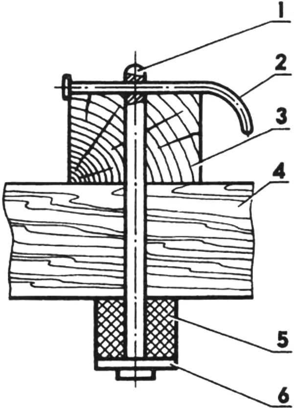
1 — pin (nail Ø5); 2 — stop (nail Ø2); 3 — deck beam support; 4 — beam; 5 — rubber washer Ø20×15; 6 — steel washer.
Of course, much is simplified in the drawings shown. Give the parts you make some rounding, sand them, and coat them several times with linseed oil.
That is, in essence, all that is needed for the frame. If you make it conscientiously, strength and durability are guaranteed. Over many years of operating «Tsarevna Lyagushka», for example, not a single wooden part of its frame broke or even cracked.
Cut the DECK from tarpaulin (the kind used to cover truck bodies is best). The deck length should equal the frame length plus allowance for pockets for the bow and stern frames; the width — the distance between the second and third stringers plus allowance for the hem. Finish the raw edges with a wide double hand-stitched seam. Sew two wide tarpaulin patches on the underside to form pockets for the middle beams. Cut and overcast holes for the bolts. When you attach the beams to the stringers, the deck should be well taut. Place the deck beam supports on the deck.
The TRUNKS differ little from ordinary boxes. Only great accuracy in manufacture is required, since during transport the bow trunk fits inside the stern trunk.
The trunk construction is the same; the materials used are not scarce: plywood 3-4 mm thick, pine strips 20×15 mm cross section, as well as small screws, epoxy glue, and piano hinges (for seat lids).
The stern (larger) trunk dimensions are 800x285x225 mm. Sew a cover for it from heavy fabric, to which attach fasteners in the form of loops and toggle buttons and a wide encircling tarpaulin strap with transverse leather tabs. Attach backpack straps to the latter. Do not remove the cover on the water. For soft sitting and convenient carrying, place a sheet of foam rubber between the seat lid and the cover.
The bow trunk should come out of the stern trunk easily. For this, drill two holes in each side and insert rope handle loops. Sew a cover only for the seat lid. Insert a sheet of foam rubber inside it and sew leather straps along the edges for attachment to the trunk. Screw the trunks themselves to the deck beam supports with bolts M6, 45 mm long (from household plumbing) with wing nuts.
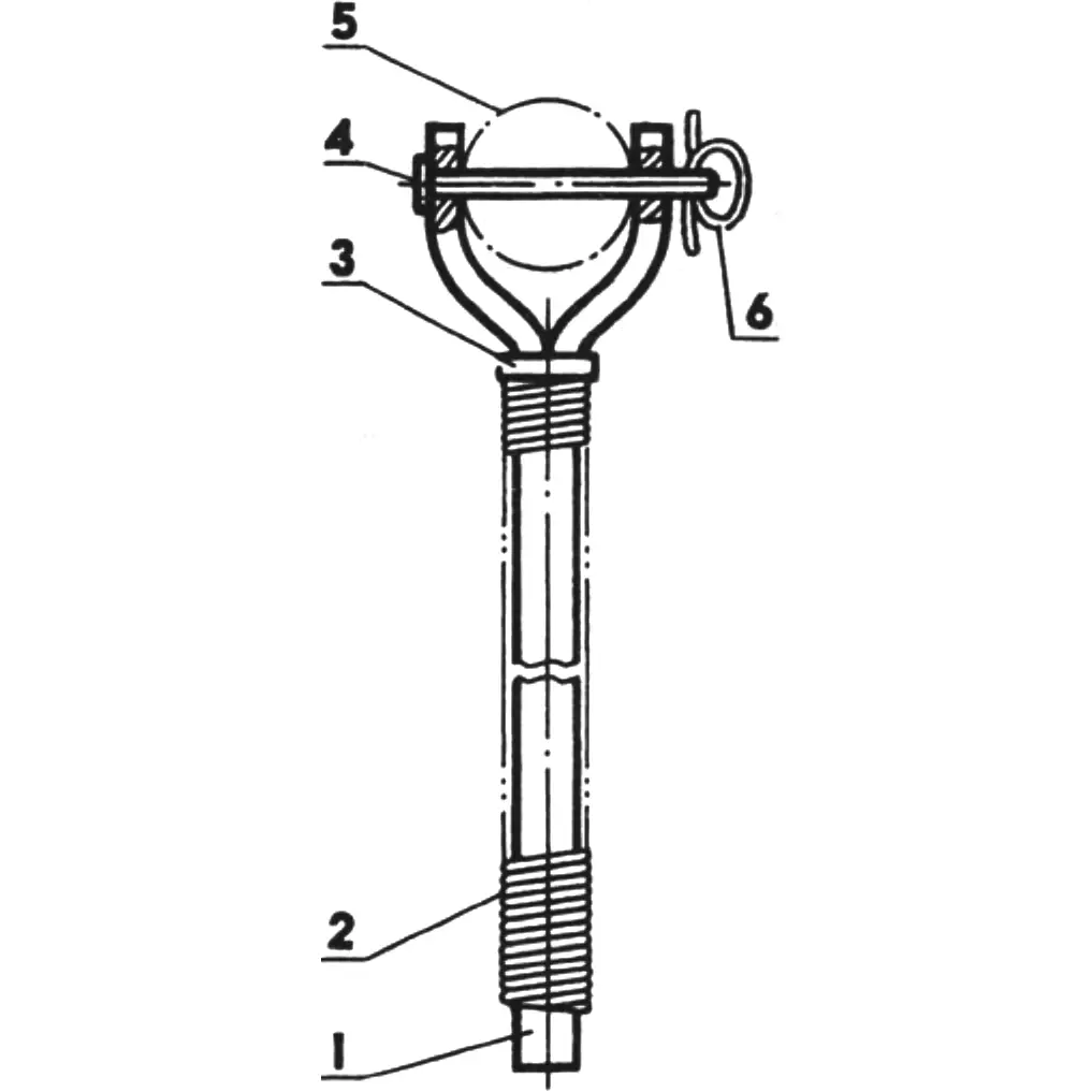
1 — horn (steel rod Ø14, L210); 2 — packing wrap (cord on epoxy resin); 3 — reinforcing washer; 4 — pivot pin (nail Ø4); 5 — oar; 6 — retainer (line Ø1).
OARLOCKS. If you cannot find factory metal oarlocks (plastic ones will not do), make them yourself from steel rods 14 mm in diameter and 210 mm long. Saw each rod along the axis to a depth of 70 mm, put on a reinforcing washer, and spread the sawn ends apart like a horn (Fig. 5). Use nails 4 mm in diameter and 65 mm long as oar pivot pins. Instead of cotter pins — pieces of 1 mm fishing line. Wrap the packing with cord on epoxy resin.
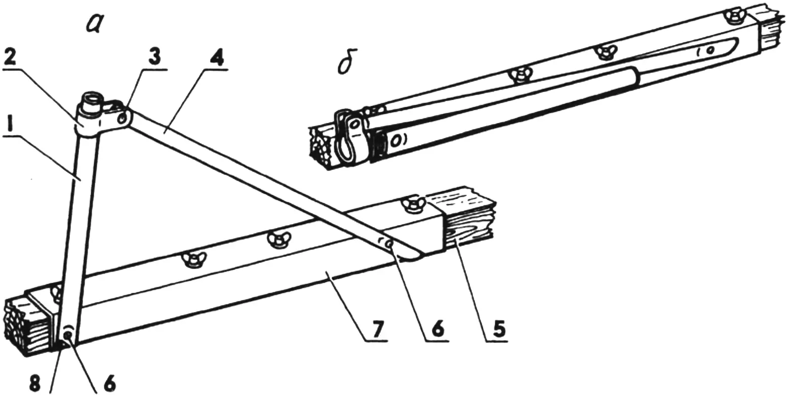
1 — socket (aluminum tube 22×3); 2 — clamp (aluminum strip 22×2); 3 — bolt M6; 4 — brace (aluminum tube 20×2); 5 — fourth stringer; 6 — folding pivots (aluminum rivets Ø6); 7 — stringer connector; 8 — insert (aluminum plate s7).
Make OUTRIGGER OARLOCKS (Fig. 6) from aluminum tubes 22 mm in diameter. Flatten their lower ends, inserting inserts — aluminum plates 7 mm thick. Hinge them (but not freely, with tension) with thick rivets to the vertical flanges of the connecting brackets of the first and fourth stringers (closer to the stern). To the same flanges (closer to the bow) attach braces in a similar manner from aluminum tubes of round (Ø20 mm) or oval section. Make the clamps from soft aluminum plate (for example, from a child’s sled back). In the stowed position the outrigger oarlocks and braces fold along the connecting brackets.
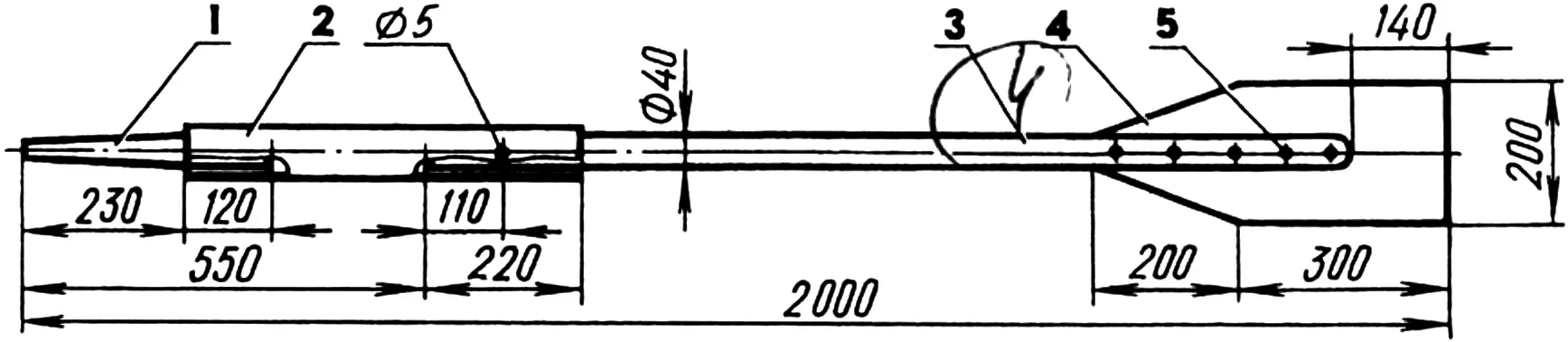
1 — handle (pine, Ø40); 2 — adapter (duralumin tube 42×1); 3 — shaft (pine, Ø40); 4 — blade (duralumin sheet s1.5); 5 — rivet (Ø4, 5 pcs.).
OARS. Their construction is clear from Fig. 7. It is desirable to use tubes 40 mm in diameter with smooth surfaces inside and out. Pole-vault poles possess such qualities.
FLOATS. What to make them from? There is no single recipe; it all depends on what one has on hand. You can use a light two-layer material called “silver cloth,” rubberized fabric on cotton or synthetic base, tent fabric, and even very strong air-transfer sleeves!
My floats, 400 mm in diameter and 3600 mm long, are made from strong shells (their fabric is somewhat denser than tent fabric), into which rubber or plastic balls are inserted through slits and then inflated. Such floats look quite decent when inflated.
What are the positive qualities of the design I chose? Low weight and reliability, since there are many “sections.” Drawbacks? The rough material slides poorly on water, “drags” it along, which reduces the catamaran’s speed. And it is also hard to get the hang of inflating the balls evenly. Incidentally, a mattress inflater will not do; you need a more powerful pump with a built-in pressure gauge.
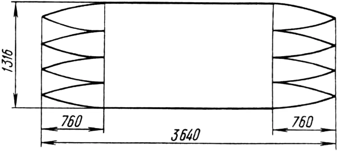
If you decide to make similar floats, bear in mind that the actual length of the shell fabric must be 40 mm greater than the nominal (hem allowance), the width — 60 mm greater (seam allowance). When cutting, do not forget that the sewn shells should taper smoothly toward the ends. Therefore cut four bow and four stern gore wedges 760 mm long in each fabric panel (Fig. 8) and sew with strong thread in several passes, leaving small openings in the bow and stern for rubber tubes from the end balls. But first be sure to attach, with basting stitches, encircling dense safety tapes to the inner surfaces of the shells (opposite the middle of each ball), ending in ties that are then fastened on the stringers. If you do not do this, in case the shell ruptures the balls will fly out like soap bubbles. This way they will stay in place.
The MAST consists of three sections: upper, lower, and middle (Fig. 9). Such division is convenient both in manufacture and in transport.
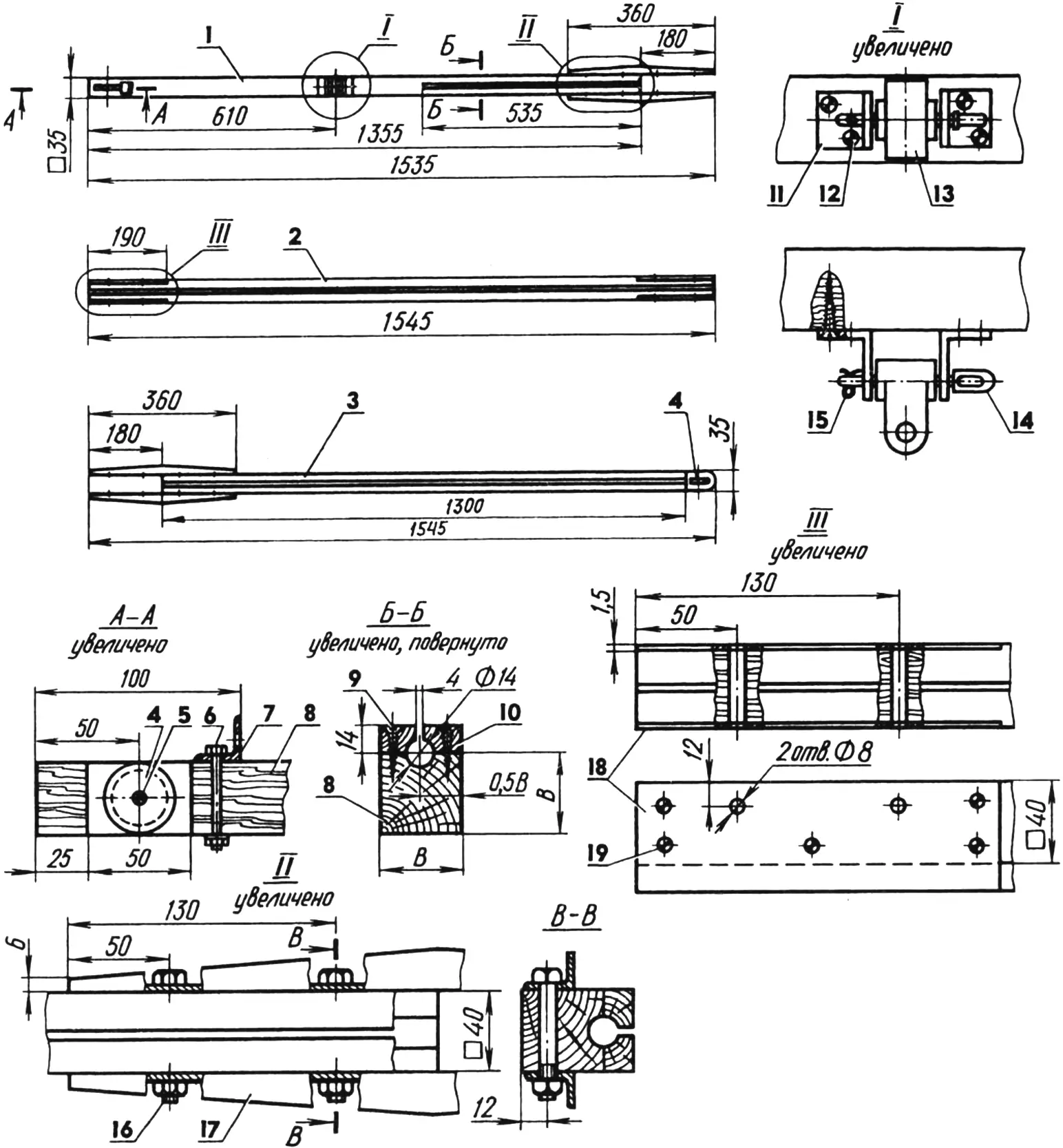
1 — lower section; 2 — middle section; 3 — upper section; 4 — halyard blocks; 5 — block axle (bolt M6); 6 — bolt M6; 7 — boom vang hook loop (angle 25x25x3); 8 — mast body; 9 — groove cover fastening screw; 10 — groove cover; 11 — boom swivel bracket (angle 40x40x4); 12 — bracket fastening screw; 13 — boom swivel; 14 — swivel shaft with tack angle retention loop; 15 — cotter pin; 16 — bolt M8; 17 — bracket (angle 25x25x3); 18 — reinforcing plates (duralumin sheet s1.5); 19 — plate fastening screw.
The main mast material is pine bars of initial 40×40 mm cross section. On the middle section keep this cross section along the entire length; on the lower and upper — gradually reduce toward the mast ends to 35×35 mm.
With a round chisel cut the groove (in the lower section — approximately to the middle). Prepare strips 14 mm thick — groove covers along its entire length. Plane them with the same chisel to finish profiling the groove and attach them to the mast sections with epoxy resin and screws. Thoroughly sand the resulting groove, achieving a smooth surface, so the sail will not jam or tear in it. And it would not hurt to sand the whole mast, giving it a so-called finished appearance.
Equip the mast ends with blocks for the halyard (wheels with a groove and axles taken from a child’s construction set), and the lower section — also with a boom swivel and a loop for the boom vang hook.
The mast sections are joined into a single whole with brackets of duralumin angle 25x25x3 mm and bolts M8. Equip with them the top of the lower section and the bottom of the upper. The ends of the middle section supply with matching reinforcing plates of duralumin sheet 1.5 mm thick, attaching them with small screws. Incidentally, do not forget to drill four holes 8 mm in diameter in the brackets (in the middle of their projecting flanges) for shroud carabiners.
On the catamaran the mast rests its step (bottom) in a step block screwed to the deck beam supports behind the bow trunk. Plane the step block from a pine bar 65×45 mm cross section (reduce the 45 mm height at the ends to 25 mm) and 430 mm long. In the middle chisel out a square recess for the step. The depth of the recess is determined by trial: if it is shallow, in sharp gusts the mast pops out easily; if too deep, the mast is twisted out by the roots.
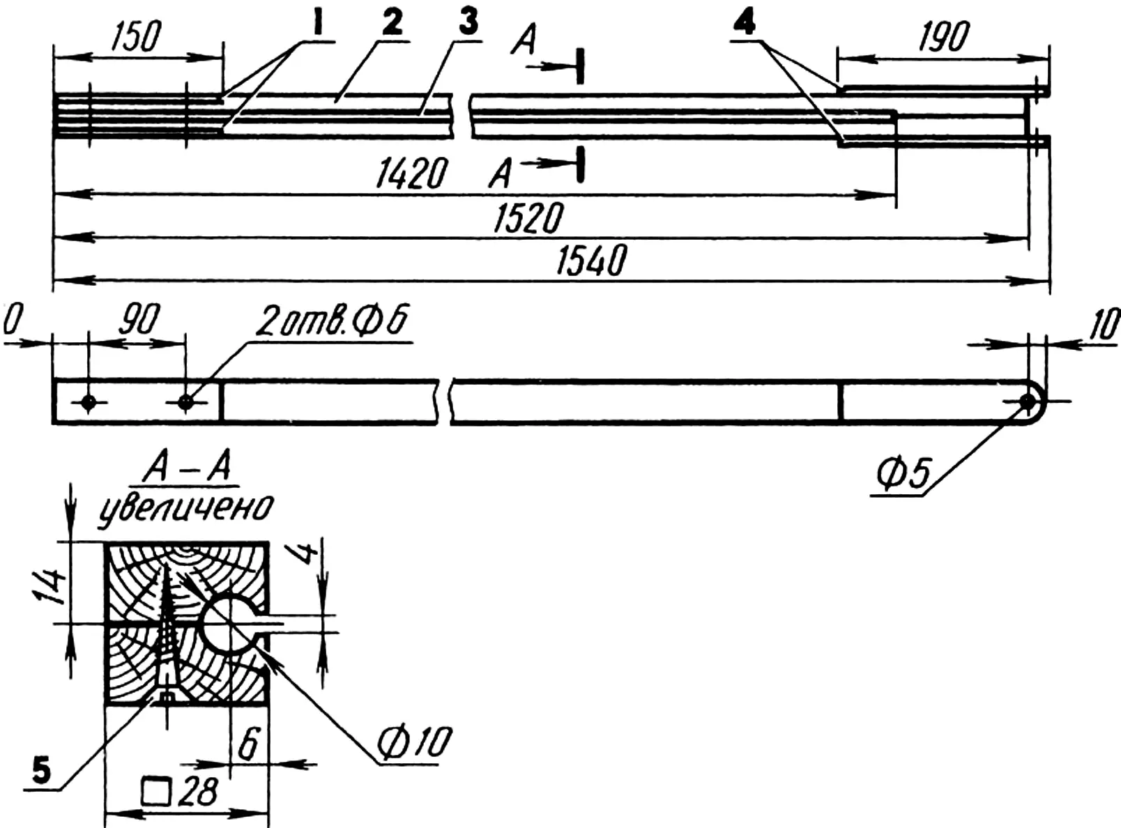
1 — plates (steel, strip s1.5); 2 — boom body (pine); 3 — groove; 4 — loops (steel, strip s4); 5 — screw.
Make the BOOM (Fig. 10) by the same technology as the mast: saw a pine bar 30×30 mm cross section lengthwise into two identical strips. Plane the groove and groove slot. Join the strips with glue and sand the boom so as to bring its cross section to 28×28 mm. Reinforce the glued seam with screws.
Fit the front end of the boom with loops — steel strips with holes for connection to the boom swivel on the mast, and the rear end — with steel plates for joining with the boom end fitting (attachment of loops and plates — with small screws, not shown in the figures).
It should be noted that the aluminum pin 5 mm in diameter connecting the boom to the swivel should fit fairly tightly in the loop holes and freely — in the swivel hole.
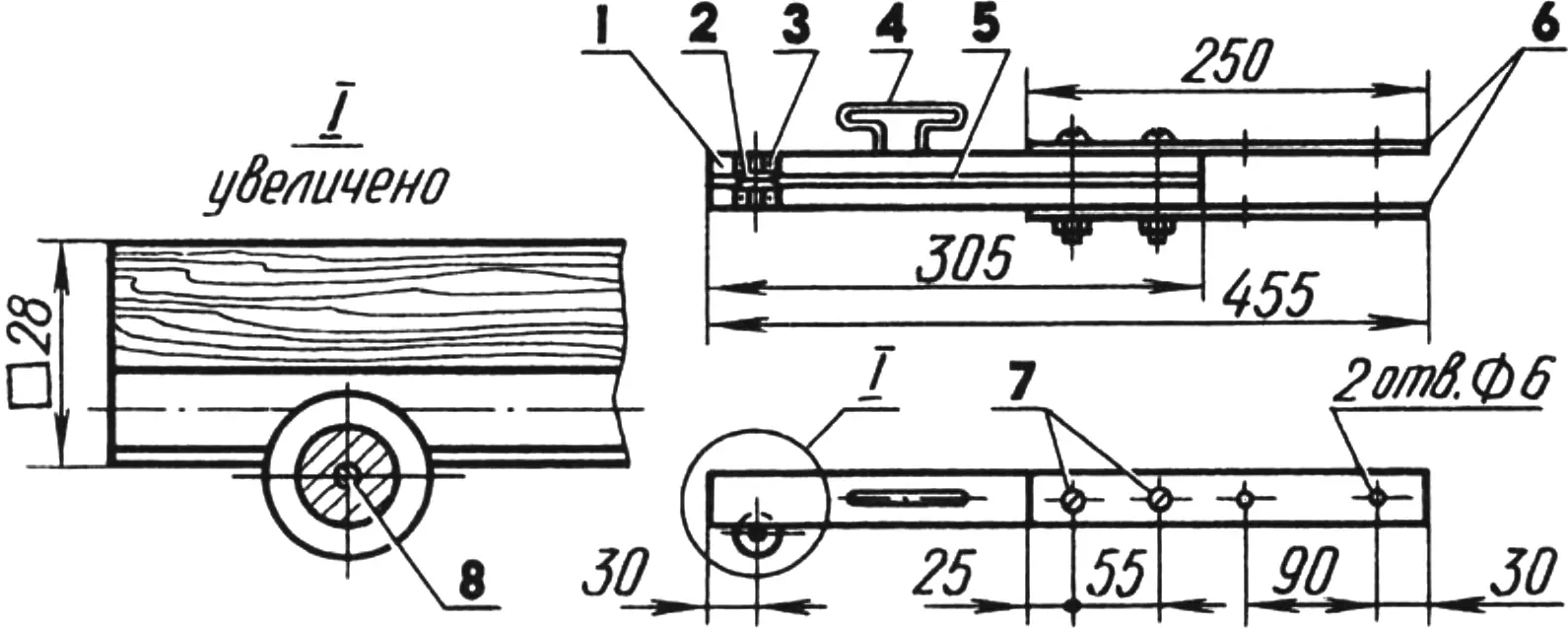
1 — fitting body (pine); 2 — block; 3 — holder (steel, strip s1.5, 2 pcs.); 4 — sheet end hook (wire Ø5); 5 — groove; 6 — plates (steel, strip s4); 7 — bolts M6; 8 — block axle (steel, rod Ø3).
The END FITTING (Fig. 11) is a removable extension of the boom. This forced division exists because the boom as a whole is too long and awkward to transport. Structurally the end fitting resembles the boom, so your actions in making it are the same. The difference is that the end fitting is fitted with a small metal block and a wire hook for the sail sheet end.
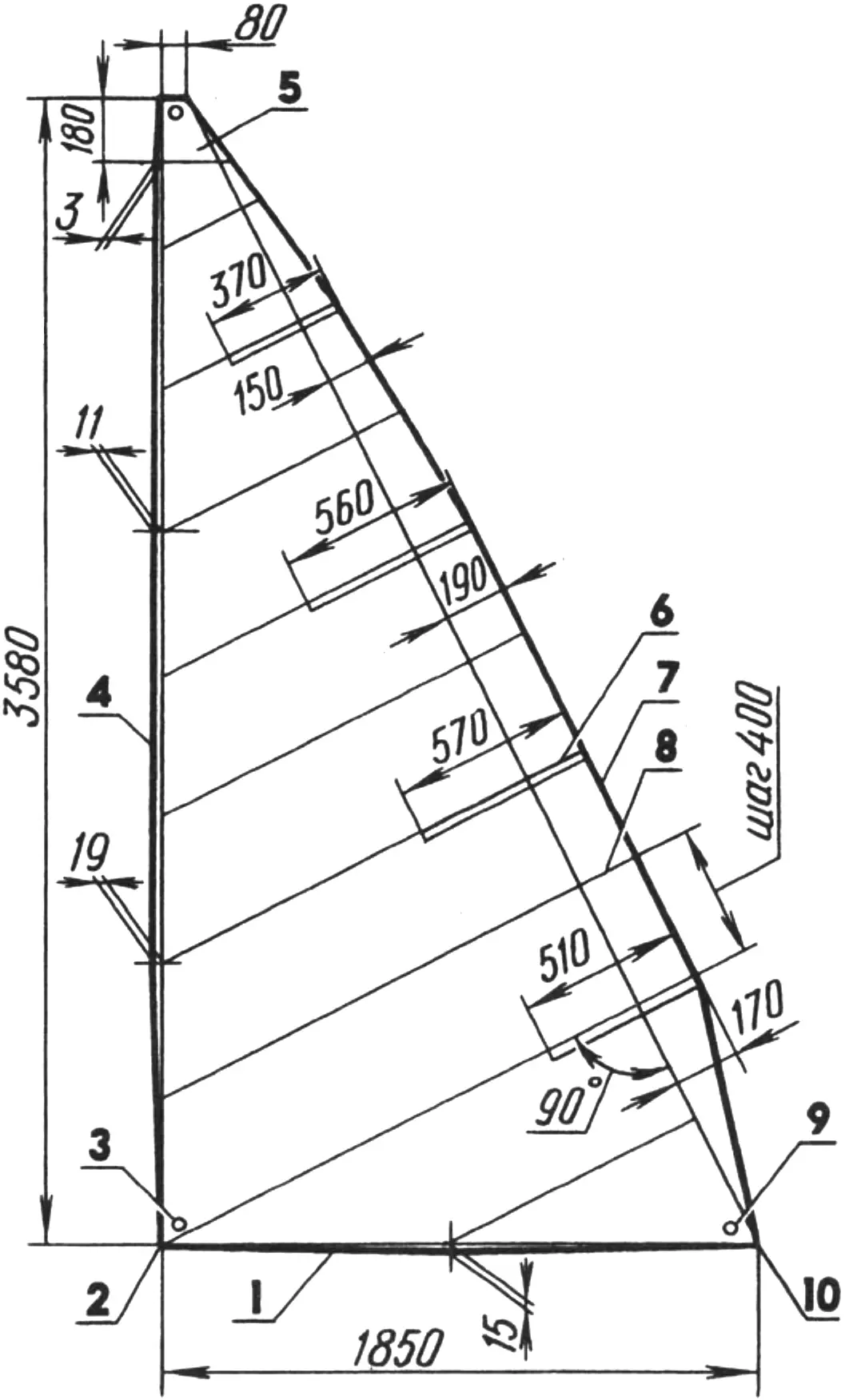
1 — foot; 2 — tack angle; 3,9 — grommets; 4 — luff; 5 — headboard (2 pcs.); 6 — batten; 7 — leech; 8 — seam; 10 — clew angle.
The SAIL (Fig. 12) is best sewn, of course, from special sailcloth. But since it is very hard to obtain and the price “bites,” dense tick-lastic or other strong fabric will do.
If the fabric roll width is 700—900 mm, the panels cut from it must be sewn in the middle with false seams with 20-mm fabric hems so the future sail will hold its shape. Lay the panels perpendicular to the leech. One of the seams must pass through the tack angle of the sail. Trim the dense edges, otherwise they will “gather.”
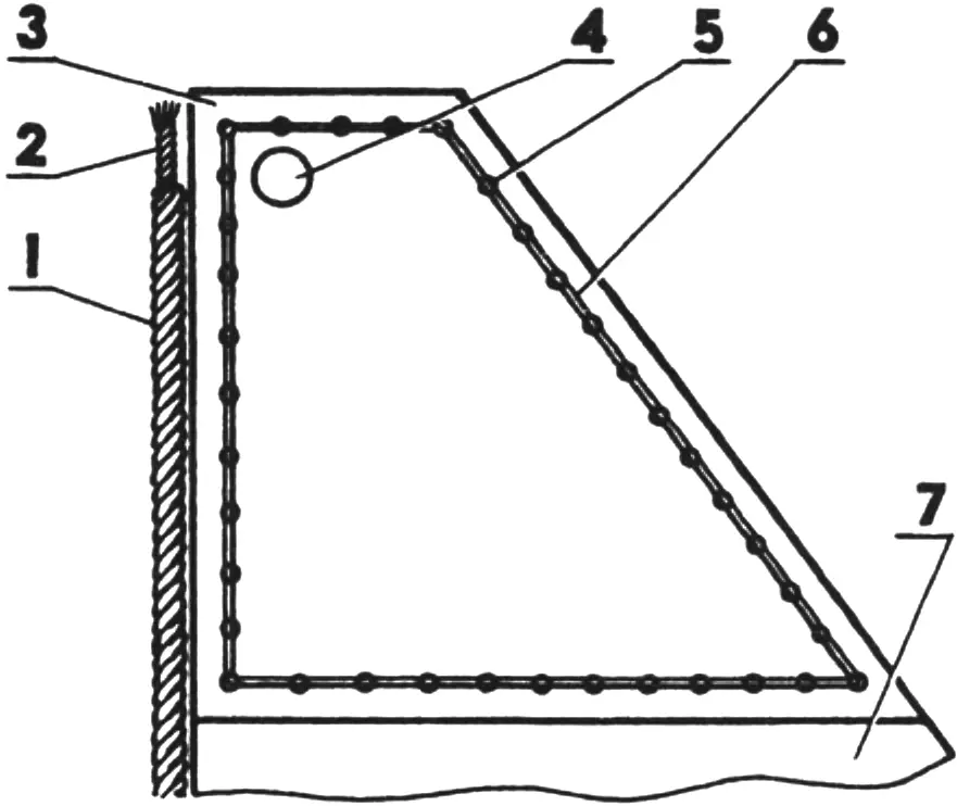
1 — bolt rope; 2 — bolt rope end; 3 — headboard; 4 — hole for halyard attachment; 5 — hole for seam thread; 6 — seam thread; 7 — sail.
Sew the sail with the widest stitches available on the machine, with minimal thread tension. At the top of the sail symmetrically attach a headboard of two duralumin plates 1.5 mm thick (Fig. 13): first drill a row of small holes along the contour of both plates together with the sail, then sew by hand through these holes with thick thread.
Widen the leech, making a “hump” that increases the sail area. And so that it has some stiffness, sew pockets for battens — long strips that can be made from plywood or school drafting rulers. The battens will not slip out of the pockets if the latter are fitted with laces and tied with reef knots. Reinforce the leech edge with an added fabric strip.
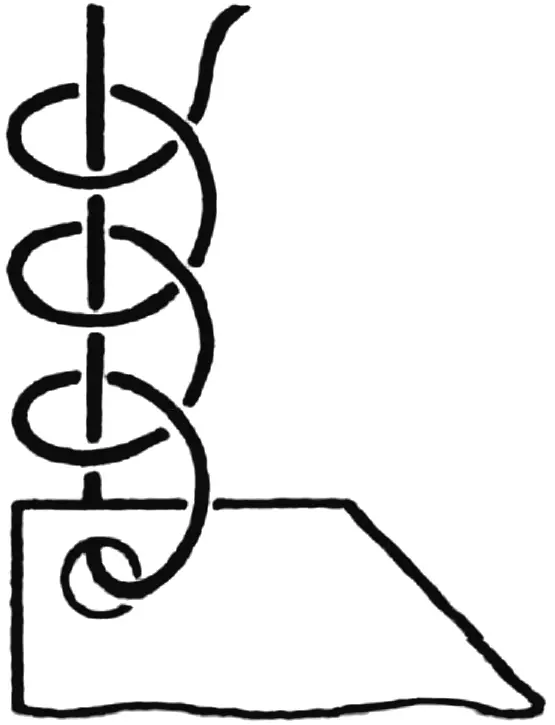
Cut the luff and foot in an arc so the sail gets a “belly” and forms a profile without which the catamaran will not go to windward. Finish the leech edges with 15 mm wide seams, sew bolt rope along the sail edge — thick twisted cotton rope that will enter the mast and boom grooves when the sail is raised. The bolt rope runs from the upper end of the luff along its entire length, then along the foot and ends at the clew angle. When sewing the bolt rope, try to keep its tension and that of the fabric equal, and the needle should pierce each strand of the rope.
The RUDDER GEAR (Fig. 15) consists of a tiller, gudgeon, and pivoting rudder blade held on a post located amidships of the fourth (stern) frame. The post is drawn to the frame with a bolt M6 with a wing nut through an angle bracket whose horizontal flange is attached to the frame with screws. In addition, the post has wire stretchers with loops slipped over holder screws fitted with thick leather washers that prevent the stretchers from slipping off. The upper attachment of the wires is clearly shown in the figure.
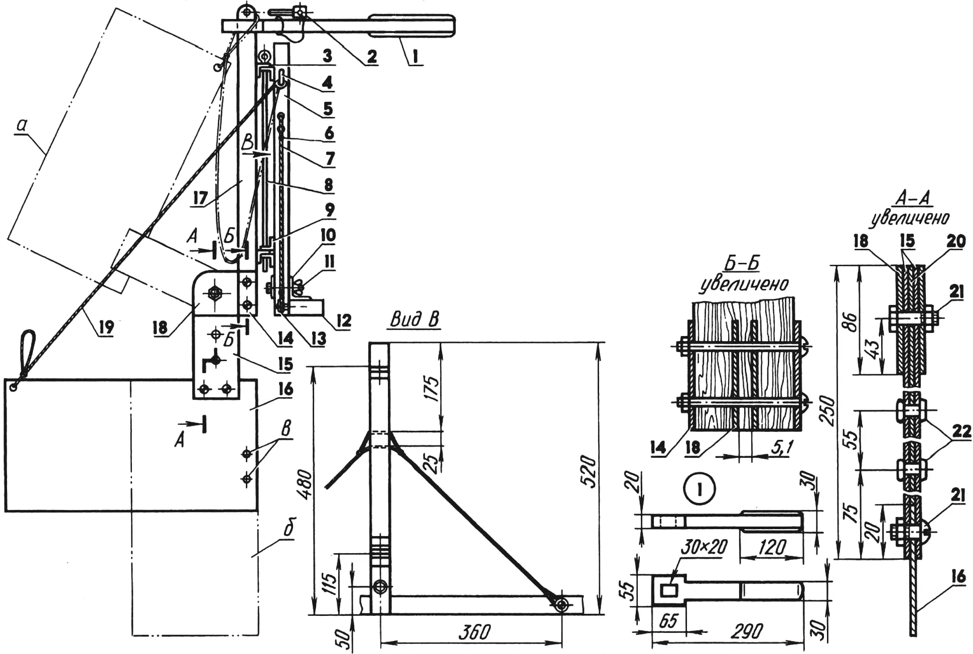
1 — tiller (plywood s10); 2 — tiller locking pin (pine, rod Ø10); 3,9 — pivot loops (duralumin, angle 25x25x3, 5 pcs.); 4 — pintle loop (nail Ø3); 5 — rudder post (pine, bar 25×25, L520); 6 — stretcher attachment knot (2 pcs.); 7 — stretcher (wire Ø3, 2 pcs.); 8 — pivot pin (steel, wire Ø5); 10 — post bracket (duralumin, angle 40x40x4); 11 — bolt M6; 12 — fourth (stern) frame; 13 — stretcher holder (screw Ø4 with leather washer, 2 pcs.); 14 — plates (steel, sheet s2); 15 — gudgeon moving plates (steel, sheet s1.7); 16 — rudder blade (duralumin, sheet 500×250, s1.5); 17 — gudgeon stock (pine, bar 40×40, L600); 18 — gudgeon fixed plates (steel, sheet s1.7); 19 — pintle; 20 — spacer (steel, sheet s1.7); 21 — bolts M6; 22 — rivets (Ø5); a — rudder blade in raised position; b — rudder blade in deep setting; c — holes for rudder blade attachment in deep setting.
The gudgeon stock is connected to the rudder post with angle loops through whose holes a long pivot wire is passed. Each loop is attached with two through bolts M6, with duralumin plates under the heads.
The moving part of the gudgeon is riveted from three steel plates 1.7 mm thick each. If their thickness is less, foil sheets must be inserted between them so the rudder blade fits freely in its intended slot.
The rudder blade is set for shallow and deep water. The second position gives it significantly greater effectiveness. The blade material is duralumin sheet 1.5 mm thick.
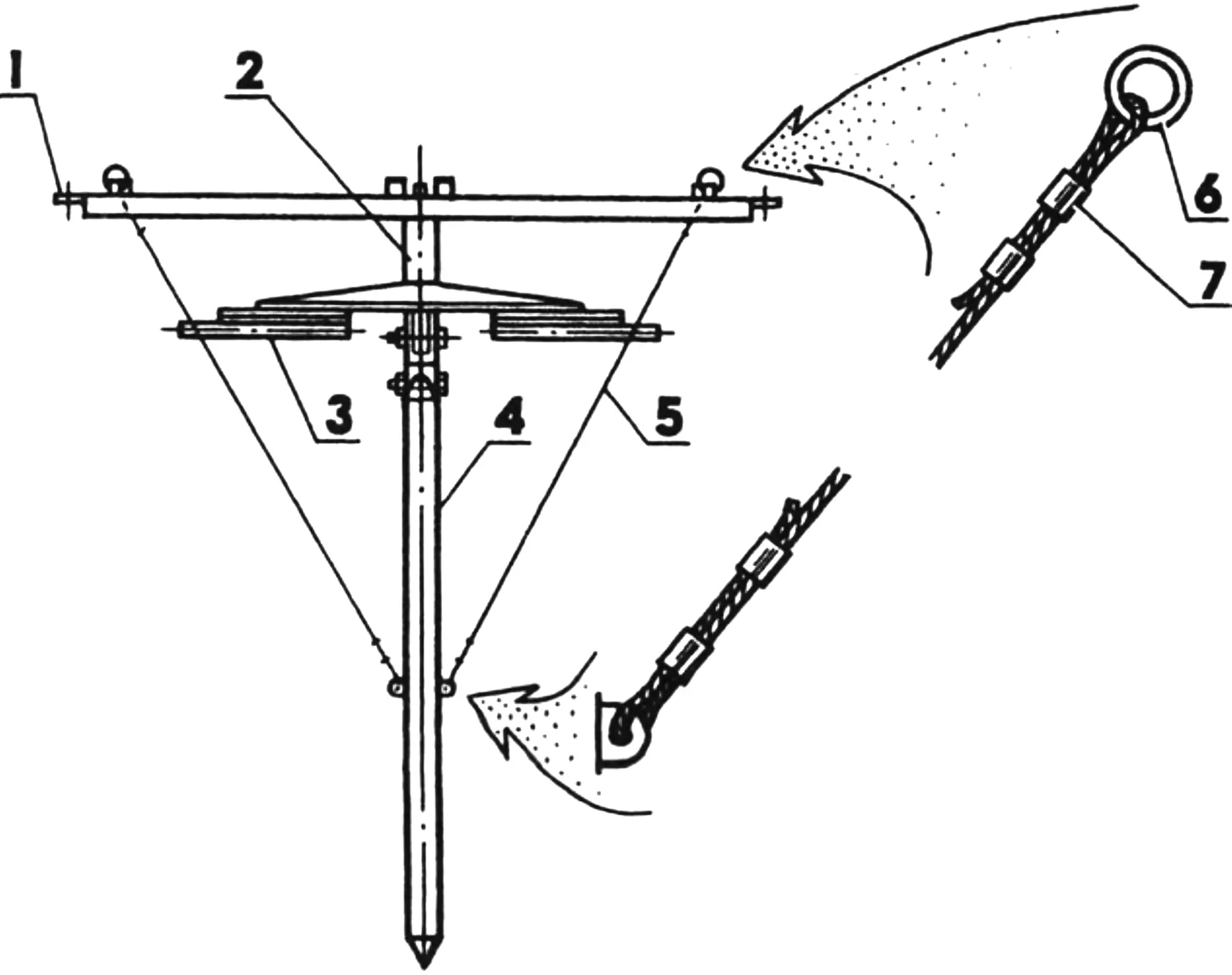
1 — centerboard beam; 2 — centerboard bracket; 3 — centerboard wire stretcher stabilizer; 4 — centerboard; 5 — stretcher (wire Ø2, 2 pcs.); 6 — stop ring (2 pcs.); 7 — crimp sleeve (copper, tube 5×4, 8 pcs.).
The CENTERBOARD GEAR (Fig. 16) consists of six main units: beam, bracket, centerboard wire stretcher stabilizer, the centerboard itself, and two stretchers. Make the latter from pieces of steel wire 2 mm in diameter, pieces of copper tube (crimp sleeves), and stop rings.
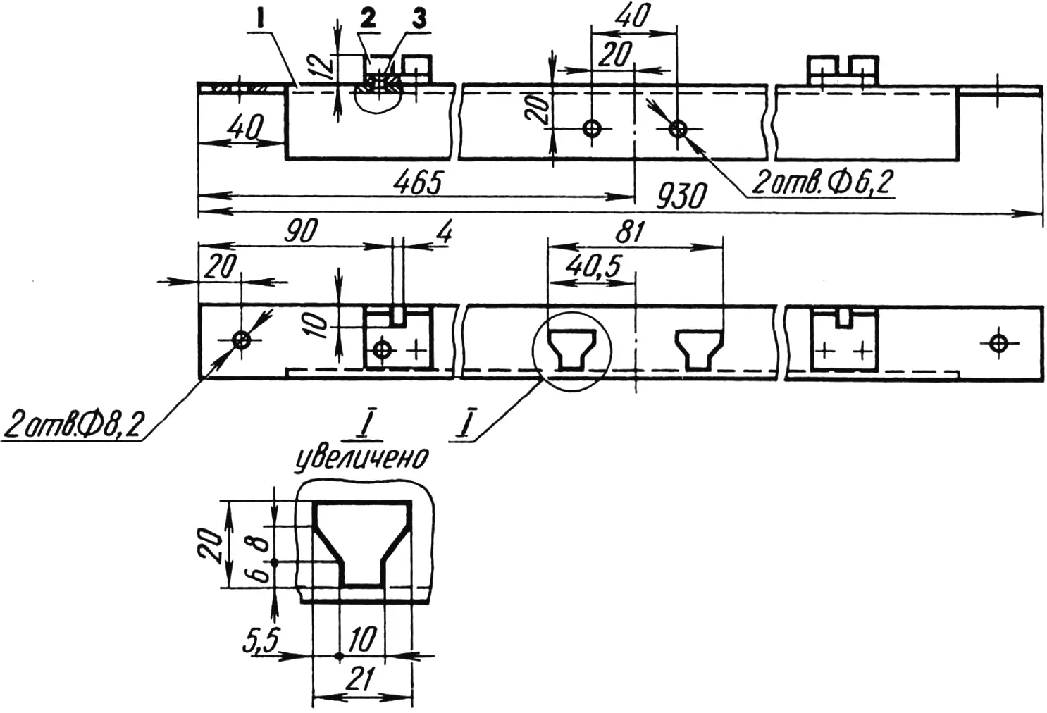
1 — beam (duralumin, angle 35x35x3.5); 2 — lock (duralumin, angle 30x30x3, 2 pcs.); 3 — rivet (Ø3, 4 pcs.).
The CENTERBOARD BEAM (Fig. 17) rests on the inner stringers and is attached to them by the third row (counting from the bow of the catamaran) of bolts M8 of the connecting brackets. Make it from duralumin angles 30×30 and 35×35 mm. Take special care when sawing the shaped holes for the centerboard bracket tenons: they must be precise.
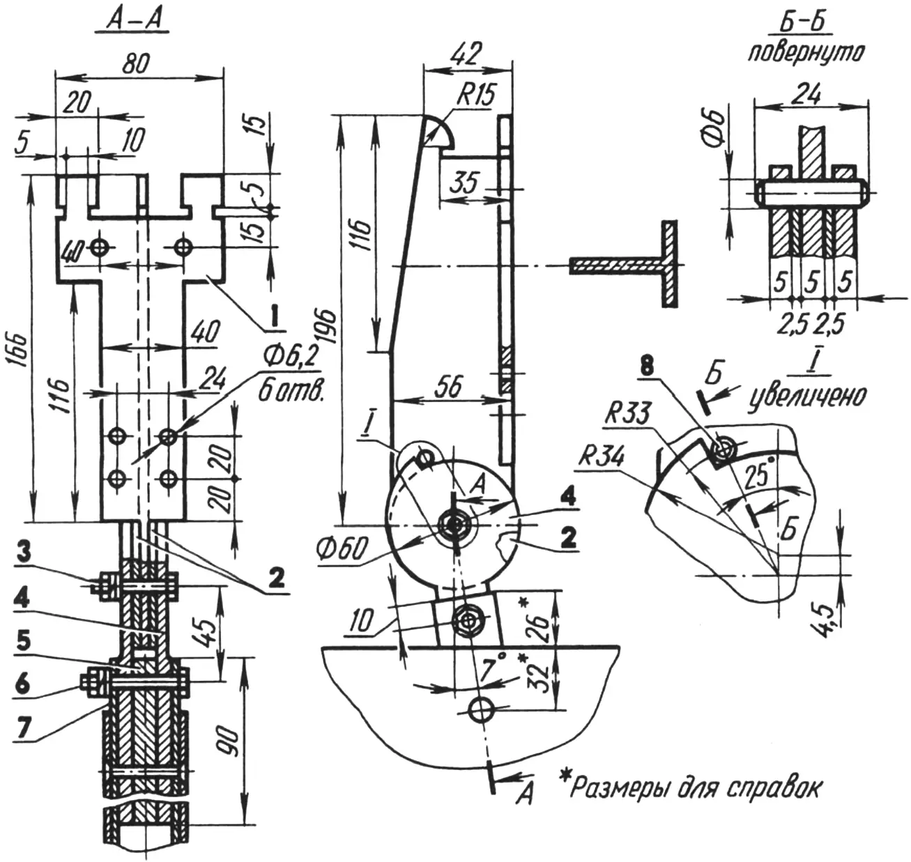
1 — bracket (duralumin, T-section); 2 — spacer washers (duralumin, sheet s5); 3 — centerboard pivot (bolt M6); 4 — hinge cheeks (duralumin, sheet s5); 5 — insert (duralumin, strip s10); 6 — lock (bolt M6); 7 — centerboard arm; 8 — stop (steel, pin Ø6).
The CENTERBOARD BRACKET (Fig. 18) may be solid, cut from duralumin T-section of suitable dimensions, or composite, riveted from several simpler profiles. Here that is not critical. The main thing is that the centerboard bracket tenons fit tightly in their allotted holes in the centerboard beam, and the radius hook reliably holds the bracket on the beam.
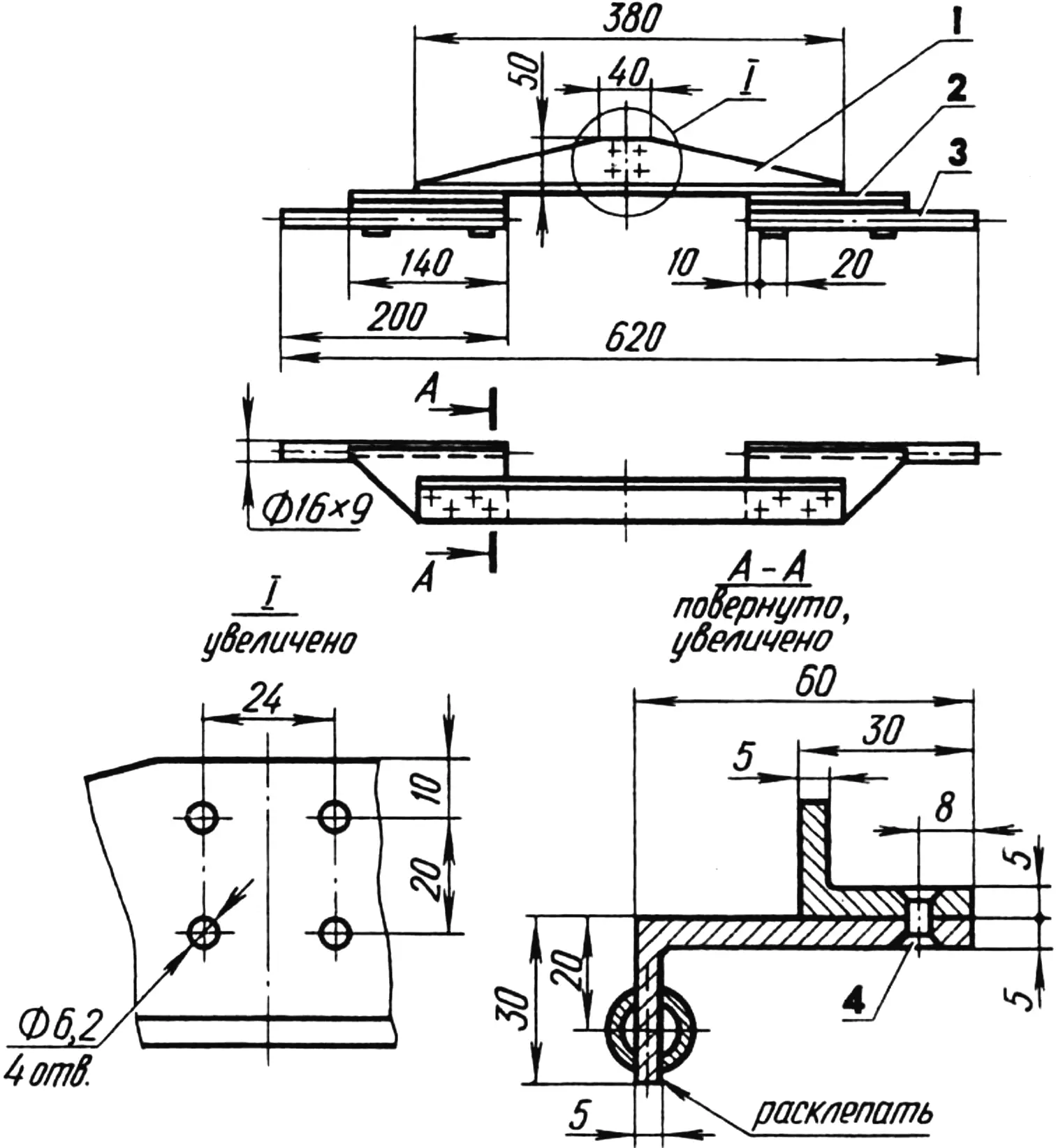
1 — beam (duralumin, angle 50x30x5); 2 — comb (aluminum, angle 60x30x5, 2 pcs.); 3 — limiter (duralumin, tube 16×9, 2 pcs.); 4 — rivet (Ø5, 8 pcs.).
The wire stretcher STABILIZER (Fig. 19) is an essential part of the centerboard gear. It ensures equal tension of the wires in any centerboard position. Then the centerboard effectively resists transverse (lateral) forces trying to capsize the catamaran. With the centerboard lowered, the stabilizer tubes keep the wires taut, preventing the centerboard from shifting aft as speed increases (forward movement is blocked by the stop) and thereby — a change in the catamaran’s lateral resistance center position.
The stabilizer construction is simple and needs no special comment.
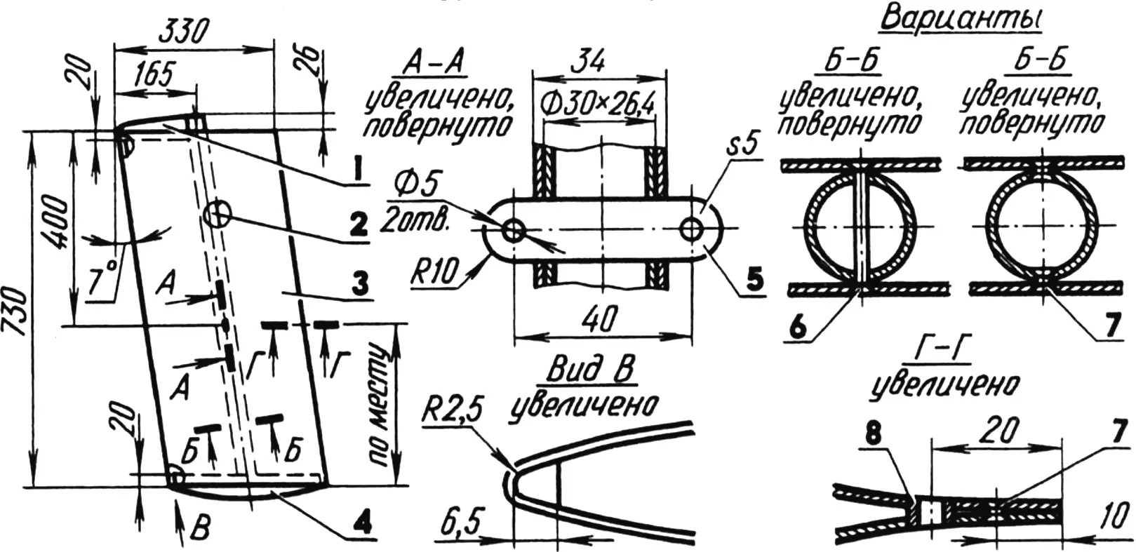
1 — upper fairing (foam plastic); 2 — arm (duralumin, tube 30×26.4); 3 — skin (duralumin, sheet s2); 4 — lower fairing (foam plastic); 5 — insert (duralumin, plate s5); 6 — long rivet (Ø3); 7 — short rivet (Ø3); 8 — thimble for centerboard lifting shackle (steel, tube 8×5).
CENTERBOARD (Fig. 20). Duralumin sheet 2 mm thick is best suited for its skin. A centerboard from such sheet will be somewhat heavy, but will give no trouble during voyages.
Calculate the sheet dimensions taking into account the profile and inclined position of the centerboard. At the bend of the sheet cut a groove with a 5 mm round file without a handle. Do not make the groove too deep, otherwise the leading edge of the centerboard will be sharp, which is undesirable aerodynamically; moreover a crack may form. Do not make the groove too shallow either, otherwise you will not manage the profile shape, and repeating the bend at that spot will be impossible — the sheet will inevitably crack.
Rivet the centerboard “tail.” Clamp the centerboard in a vise with plywood pads and insert the arm — a duralumin tube 30 mm in diameter (a piece of a pole-vault pole). It may not reach the bottom of the centerboard. Join the arm and skin with rivets. This can be done using either long through rivets or short ones. With short rivets insert them from inside the arm first into the holes of one future riveted seam, then insert a mandrel into the arm — a steel water pipe of suitable diameter (it must fit tightly in the arm!) and peen the protruding rivet ends. Remove the pipe and repeat these operations on the other side of the centerboard.
Profiled fairings are necessary so that the centerboard is washed optimally both in shallow and deep settings. Cut the fairings from foam plastic, wrap with several layers of gauze impregnated with epoxy resin, and glue into the centerboard. Note: between the leading edge and the lower fairing there is a small drain hole through which water that gets inside drains from the centerboard, since the centerboard is not watertight for simplicity of construction.
The centerboard is hinged to the centerboard bracket by means of several intermediate parts whose construction is clearly visible in Fig. 18, so I will not dwell on them in detail.
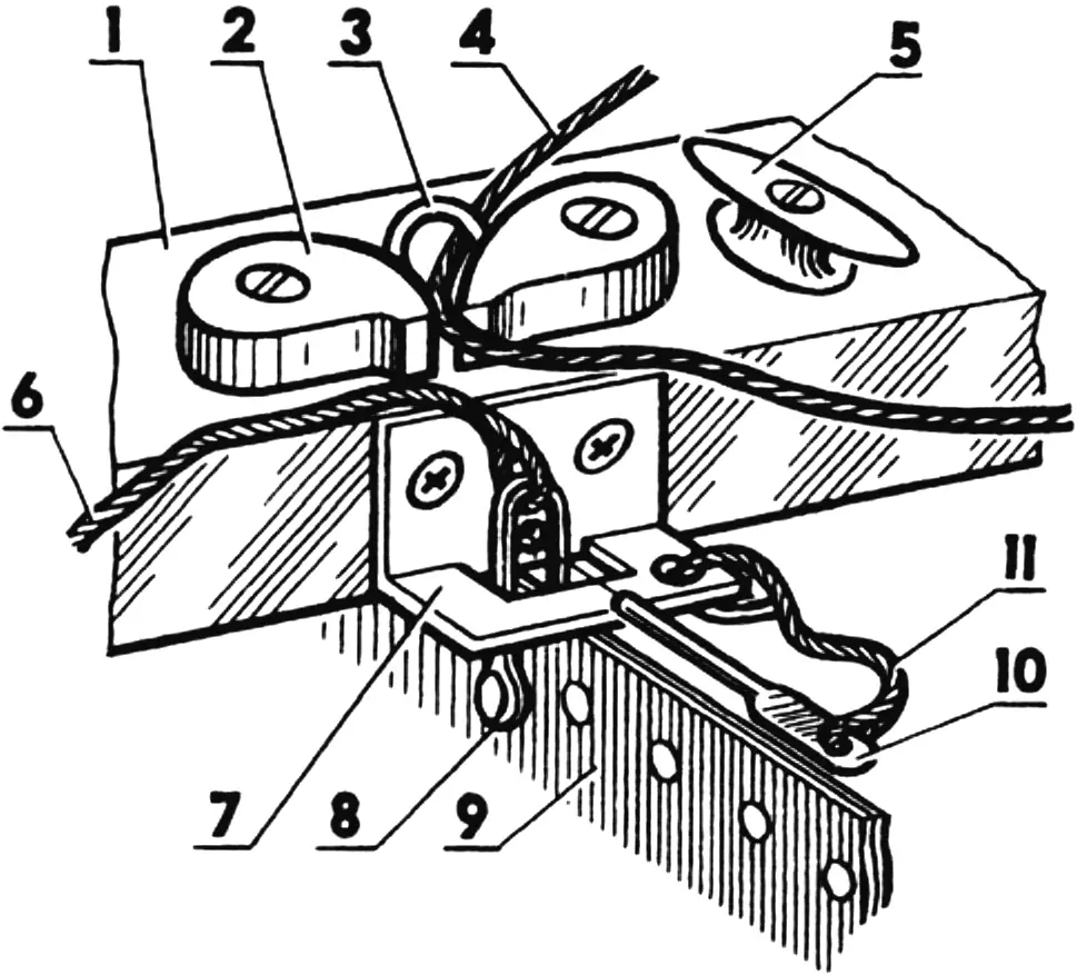
1 — third frame (midship, view toward bow); 2 — boom sheet stop (2 pcs.); 3 — stop bow; 4 — boom sheet (cord Ø6); 5 — halyard hook; 6 — centerboard lifting cord; 7 — sheet attachment bracket (duralumin, angle 30×30); 8 — centerboard rigging shackle (type 5); 9 — centerboard in raised position; 10 — pin (rod Ø5); 11 — safety cord.
How the centerboard is fixed in the lowered position is shown above. In the raised position the centerboard is held by a wooden pin inserted in a hole of a special angle bracket attached to the stern edge of the third frame (Fig. 21). Next to this bracket are also hinged boom sheet stops and the halyard hook.
The REMOVABLE CHASSIS (Fig. 22) is a very useful accessory to the large (stern) trunk. It allows one person to easily transport the disassembled catamaran on it. The chassis construction is shown here without details, since simpler variants are possible. Wheels 220 mm in diameter with 50 mm wide tires — from a hand truck. Of course, such wheels are heavy, but they are more reliable than light “tube” wheels that may fail at the most inopportune moment.
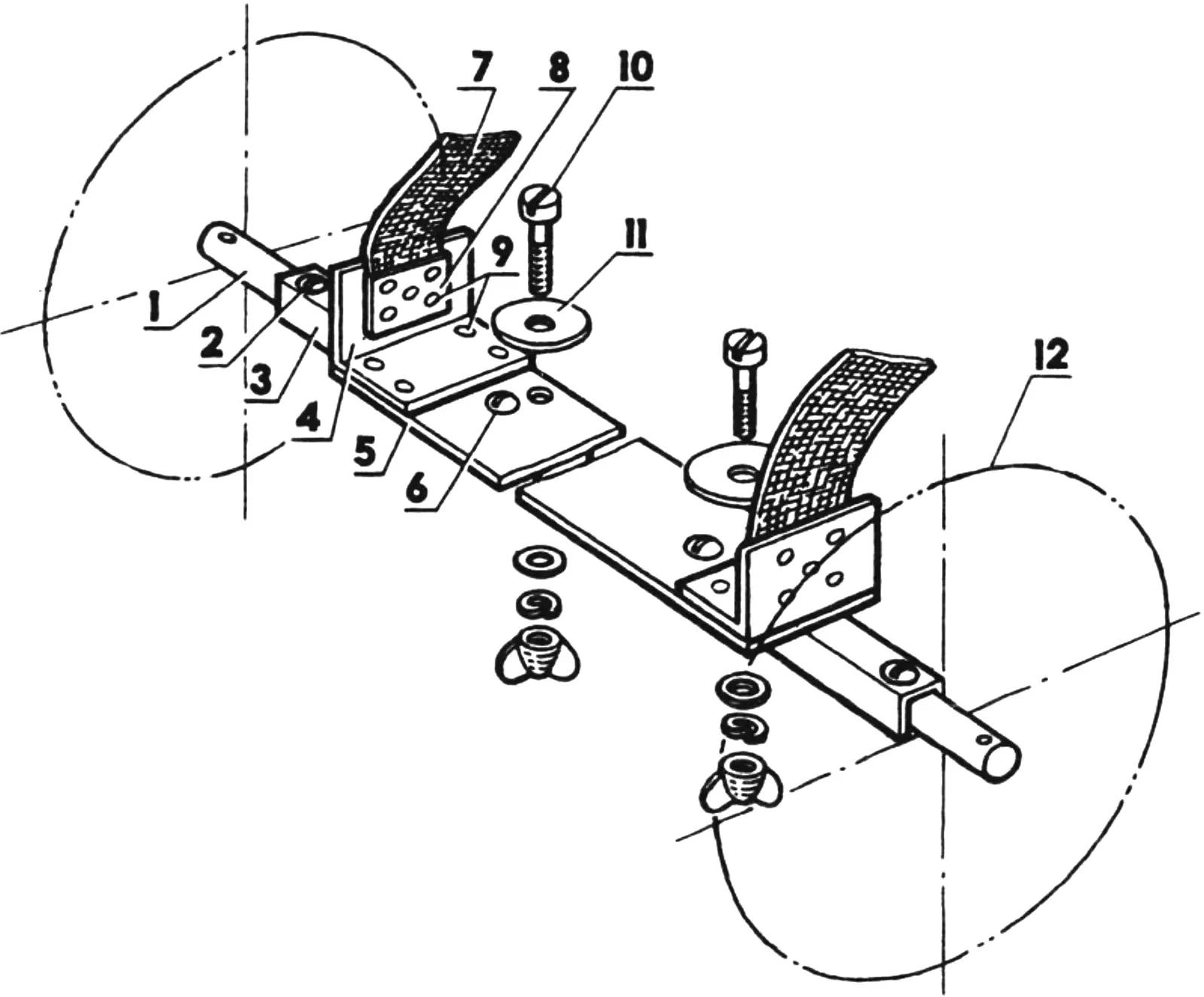
1 — wheel axle (steel, rod Ø14, L530); 2,6 — screws M6 (4 pcs.); 3 — axle housing (duralumin, U-channel 20x20x3, L380); 4 — bracket (duralumin, angle 40x40x3, 2 pcs.); 5 — platform (duralumin, sheet 310×70, s2); 7 — strap (tarpaulin, tape 45×3, L850, 2 pcs.); 8 — plate (duralumin, plate 30×20, s1.5, 2 pcs.); 9 — rivets (Ø4, 18 pcs.); 10 — trunk attachment bolt M8 (2 pcs.); 11 — washer (Ø80, s2, 2 pcs.); 12 — wheel (Ø220, 2 pcs.).
The chassis is an axle to which are screwed a housing (U-shaped channel) that gives the fairly long axle rigidity, and a platform (a sheet-metal rectangle). To the latter are riveted angle brackets and straps. In this form the chassis is attached to the bottom of the large (stern) trunk with two through bolts M8 on wing nuts.
In addition, on this trunk at the front there is a non-removable swivel device with a wheel of smaller diameter. Today it is hard to obtain a quality swivel device. Those sold look nice but are made of soft metal and not designed for heavy loads. Therefore I offer a schematic drawing of such a device and its attachment to the trunk (Fig. 23).
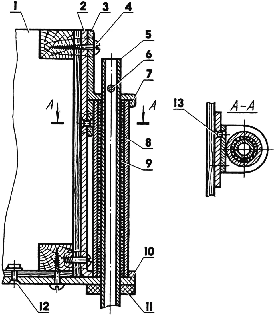
1 — stern trunk (without lid); 2 — vertical plate (steel, plate 225×50, s4); 3 — upper bracket (duralumin, angle 60x30x4); 4 — screw (Ø4, 4 pcs.); 5 — swivel axle (duralumin, tube 14×8); 6 — cotter pin; 7 — lower bracket (duralumin, angle 30x30x4); 8 — socket (duralumin, tube 16×20); 9 — “bearing” (wrap of thick thread glued with epoxy resin and greased with grease); 10 — lower plate (steel, plate 120×50, s4); 11 — shock absorber (leather, washer Ø30×14, s5); 12 — rivet Ø4 with cylindrical head (2 pcs.); 13 — rivet Ø4 with countersunk head (2 pcs.). Wheel attached to the lower end of the swivel axle is not shown for clarity.
But before installing the swivel device in its allotted place, reinforce the bottom and front wall of the trunk with steel plates 4 mm thick.
In conclusion, a few recommendations.
It is good if you can divide construction of the catamaran into three stages. The result of each will bring you joy.
The first stage — making the frame, deck, floats, seat trunks, and oars. In the end you have a four-place disassemblable rowing boat!
The second stage — attaching the rudder gear and a light mast with a spritsail — a rectangular sail. Now you are a tourist on any stream!
And the third stage, the most responsible and difficult — making the profiled duralumin centerboard, a high strong mast, sewing an aerodynamic sail. From this moment you are a full-fledged yachtsman on a big river, a wide reservoir!
For packing on the road, make a list of all catamaran parts grouped by transport units. Without it you risk returning without having sailed. Pay special attention to small items. Sort bolts and pins into sets in separate bags and put it all in a pouch.
Tie large parts — beams and stringers — in fours, wrap in the tarpaulin deck and buckle with two straps with a bamboo handle. Stow the centerboard beam there too in a “sock.” Metal brackets — in little covers. Lay mast sections and stern deck beam supports with metal ends in one direction, buckle with three straps with plywood pads under them so nothing rattles, and fold into a narrow cover metal end forward. Stow oars and oar handles inserted one into the other there too. Pack everything else as you see fit; only tools, first-aid kit, spare parts, knife, and money should always be at hand.
Insert the small (bow) trunk into the large (stern) one, fold touring gear into it. Lay the disassembled catamaran on the trunk. All cargo “units” should be in a definite order, covered with cases, cinched with straps with bamboo handles, and firmly secured with encircling belts. On top tie the centerboard in a cover with cords threaded through tarpaulin “loops,” the cover with connecting brackets and wire stretcher stabilizer, and all other small items. Crown the load with a backpack — why drag it on your back? Forgot nothing? Off we go!
On arrival, begin catamaran assembly with the frame, inserting the beams into the deck pockets. Do not screw the wing nuts too tight — spare the wood.
Remember that over-inflated floats absorb waves along the gunwale worse, do not increase load capacity, and may burst when the sun “wishes” to increase their volume.
At first assembly and disassembly of the catamaran will take you a great deal of time. Do not despair! I alone now manage this work in three hours.
When setting out on a voyage, remember that a person on the water is weaker than a cat — and must pay for the pleasure with the strictest observance of water safety rules. The catamaran is a sturdy and reliable craft, but only when correctly assembled. A catamaran with a float not tied to the inner stringer shakes an unlucky crew into the water, and with a float not attached to the gunwale may capsize and cover them with its entire mass. Therefore life jackets are mandatory for children and adults who cannot swim, preferably inflatable two-section ones. A life ring is also necessary aboard.
To handle the sail competently, familiarize yourself with the relevant literature and acquire practical skills. Weather conditions on the water change fairly often and sharply, and within a short time. Remember that when wind speed increases, for example, threefold, the aerodynamic force of the sail increases ninefold! And until you have these skills, learn, if need be, to lower the sail quickly and switch to oars — they are powerful — their lever is close to that of a racing boat oar.
In recent years discipline on the water has tightened considerably, and competent behavior is required of every participant in water traffic. Therefore never “dash across” in front of large vessels. A passenger steamer goes much faster than it seems to you, and you, conversely, are significantly slower than you suppose. Incidentally, to go out on a major navigable river you must pass inspection and obtain a boat license.
And lastly. To come to love water tourism takes a certain temperament. Things are not always good: now you err in the weather forecast, now you miscalculate current speed or wind strength and direction. Moreover maps often contain gross errors in mileage; dams and locks are not marked. In connection with this many will prefer a quiet walk in the park and a warm bath in the evening to an unexplored route, but they will never experience those emotions that fall to the lot of the water tourist.
When all around is quiet and the catamaran glides silently over the water, the soul fills with wonderful feelings. Those that prompt Italian gondoliers to sing, and moved Schubert to create the barcarolle — one of the peaks of world musical art.
But now the wind sharpens abruptly — and foamy “whitecaps” appear on the darkened water. The catamaran, nevertheless, continues its confident run over the waves. You feel this confidence; it is transmitted to you, kindling the excitement of the struggle and the joy of victory over the elements.
Main data of the catamaran «Tsarevna Lyagushka» (Princess Frog)
Length, m 3.60
Width, m 1.60
Float diameter, m 0.40
Mast height, m 4.265
Draft at full load, m:
with floats 0.14
with centerboard 0.69
Sail area, m2 4.0
Centerboard and rudder area, m2 0.37
Number of passengers, pers. 4
Load capacity, kg 360
Maximum mass with chassis, kg:
with full outfit 60
with partial outfit 53
«Modelist-Konstruktor» No. 5’99, No. 6’99, D. VAKHLAMOV
Recommend to read
 TWO CLOTHESPINS
privernuty screws to a wooden cube, to help you quickly and accurately to solder the two conductors. MOTOR TRUCK
In a country HOMESTEAD or farm, however small, any mechanized cargo vehicle can help a lot. It helps to save money and power. Of course, when it is simple and reliable. Preferably, the...
