Having a stove in a garden house (coal or wood-fired), it’s quite possible to provide hot water for the kitchen sink and even a shower. You’ll need a water heater – a device that allows you to use the heat of hot gases exiting through the stove’s chimney.
Design and operating principle. The water heater pipe is built into the chimney as close as possible to the stove. Hot water from it flows through pipes into a metal cylinder (for example, from a fire extinguisher), which has a coil connected to the water supply network and to a faucet above the sink. The water filling the cylinder is heated by the boiling water entering the heater’s coil.
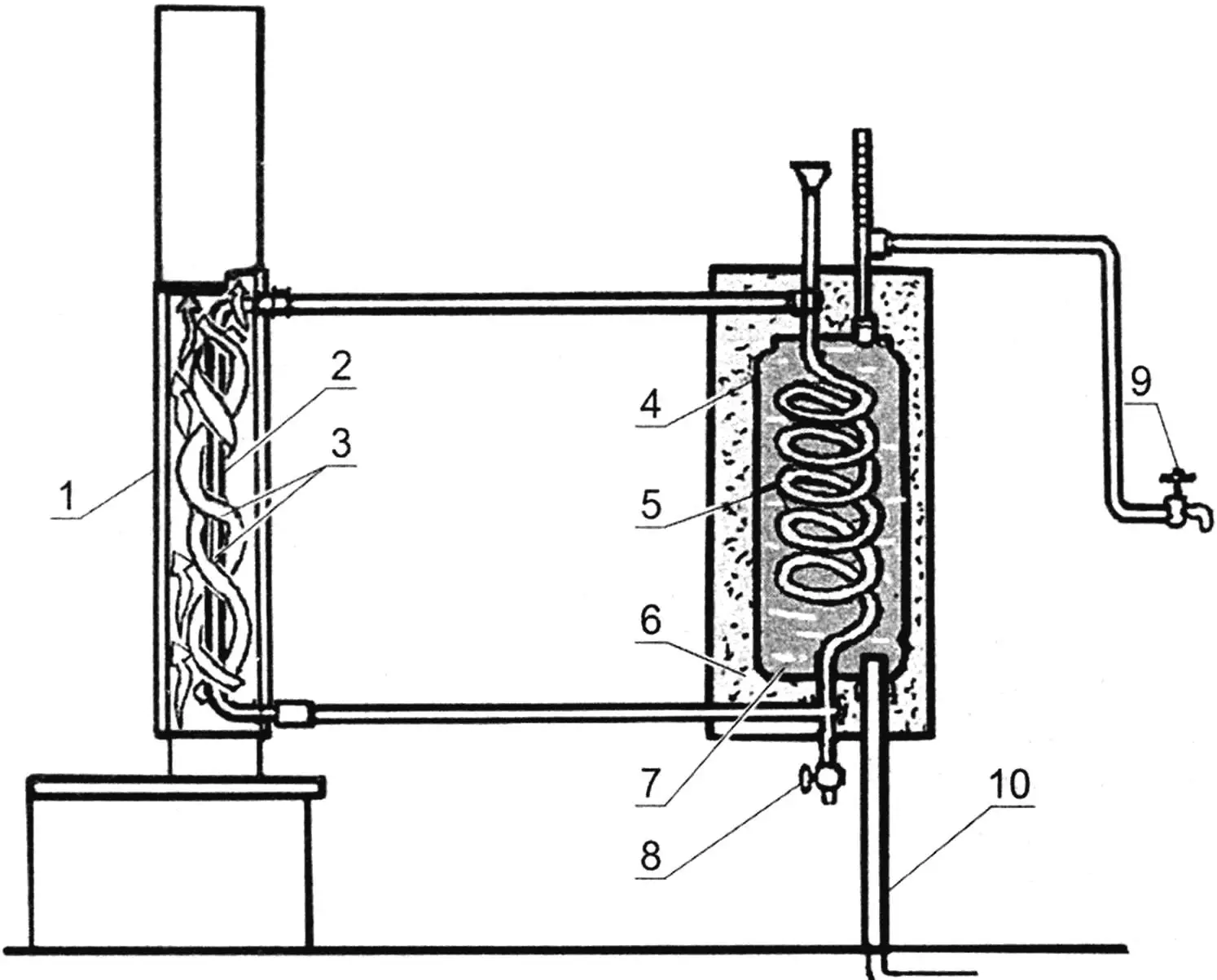
Schematic diagram of the water heating system:
1 – heater housing; 2 – water heater elbow; 3 – pipe heating reinforcement plates; 4 – heat accumulator cylinder; 5 – coil; 6 – thermal insulator; 7 – heated water; 8 – coil drain valve; 9 – supply valve; 10 – water supply
Manufacturing the heater. The water pipe elbow in the chimney has a length of approximately 700 mm. This is the main element of the heating device, it has threads on both ends for tubular connection with the coil. Two strips of sheet metal, shaped into a spiral with several turns around the pipe, are welded to this elbow. To facilitate bending the spiral, you can make transverse cuts on it with metal shears. The connection between the pipe and spiral must be tight enough to achieve maximum thermal conductivity (in accordance with this requirement, a continuous weld must be made). This part of the water heater is covered with a tin housing in the form of a pipe connected to the stove firebox outlet and constituting the lower element of the chimney. To facilitate cleaning, part of the housing is removable.
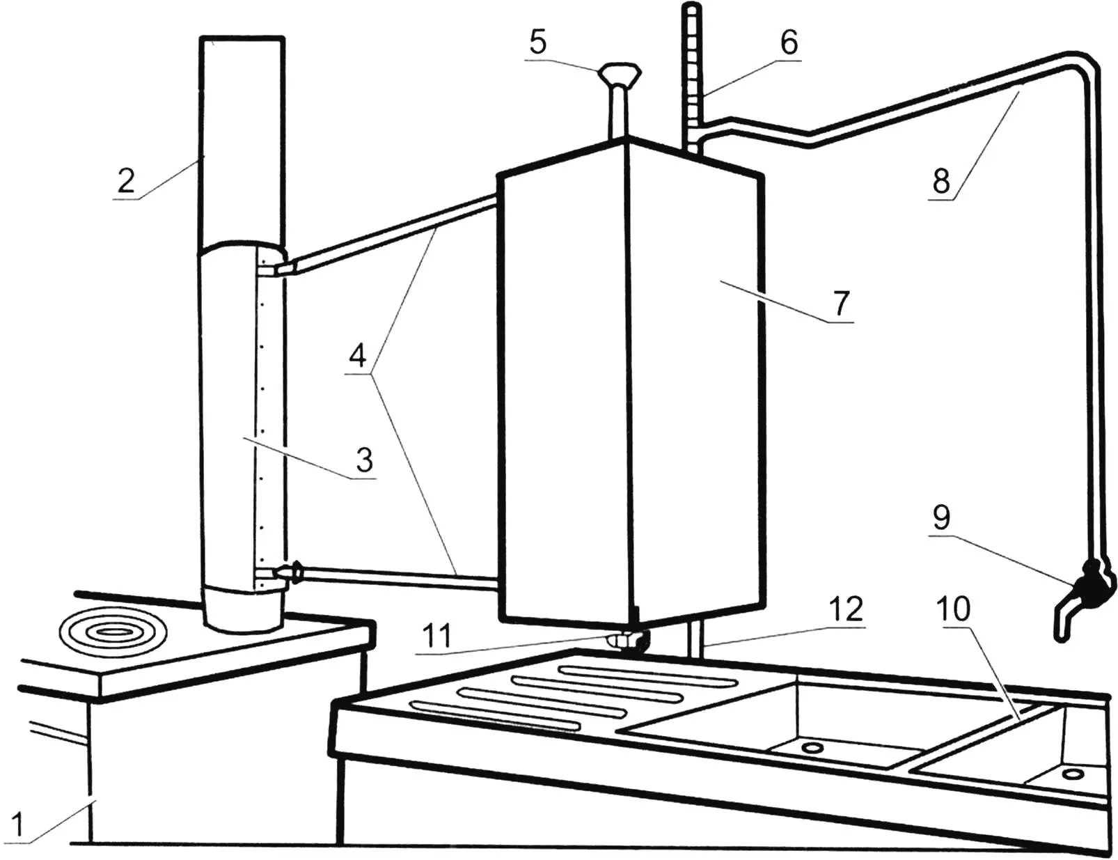
1 – stove; 2 – chimney pipe; 3 – heater housing; 4 – pipes to coil; 5 – fill neck; 6 – thermometer; 7 – “thermos” box; 8 – pipe to supply valve; 9 – supply valve; 10 – sink; 11 – coil drain valve; 12 – water supply
The water heater coil is made separately and built into the cylinder so that it’s possible to make a tubular connection with the heater in the chimney. The cylinder itself is connected to the water supply and to a fitting with a thermometer and supply valve. In the upper part of the coil there is a pipe with a funnel for filling water in case of absence of water supply feed. The cylinder is filled with water from below from the water supply (or from a water container in the absence of central water supply). Another pipe section (from above) connects the cylinder to the internal water supply – to the sink or shower. The supply valve at its end provides hot water supply to the sink.
Installation and use. The cylinder in a thermal insulation box is mounted on the kitchen wall as close as possible to the sink and stove. A short connecting pipeline will avoid unnecessary heat losses. Two pipes from the heater elbow are connected to the cylinder with standard tees. If possible, it’s desirable to position the pipes horizontally to ensure normal water circulation in the system.
An important point in setting up the system is assembling the “thermos” box. A housing with holes for pipeline passage is made from plywood or boards 8-10 mm thick. The space between the cylinder and housing is filled with any thermal insulation – for example, fiberglass.
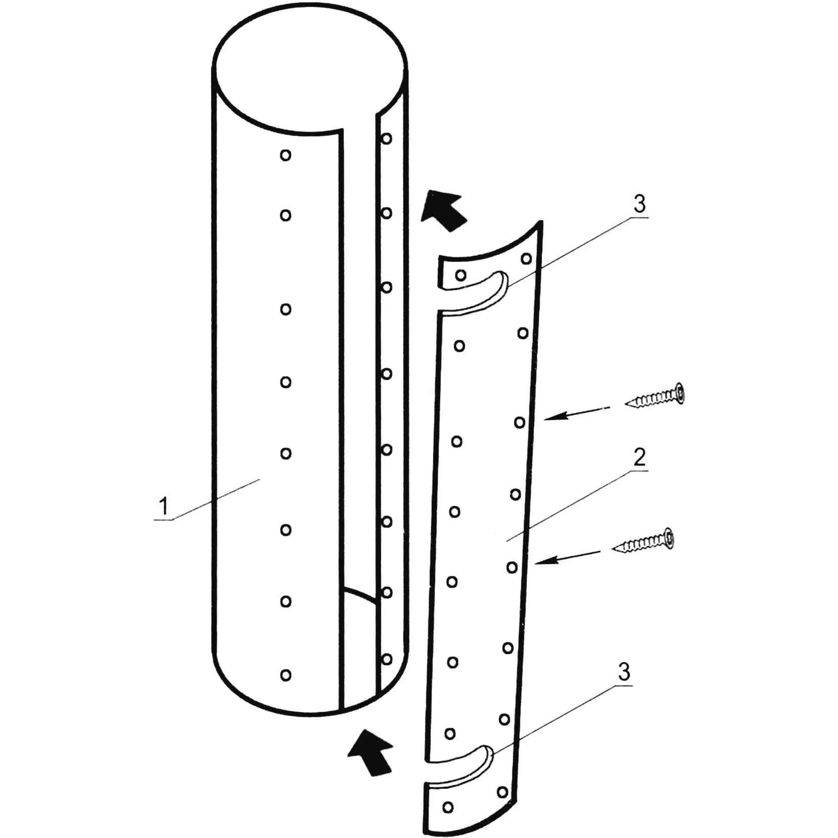
1 – chimney spacer; 2 – fixing plate; 3 – holes for water heater pipes
The water heater and coil are filled with water when lighting the stove. It’s filled not to the brim, so there’s room for volume expansion.
When the cylinder is connected to the water supply, it’s under pressure; and if there’s air in its system – you should open the supply valve at the sink to release air from the pipes.
The stove is lit, water in the heater begins to circulate under the influence of temperature differences in different parts of the system, heating the water in the cylinder. Hot water from the cylinder is consumed through the valve at the sink and automatically replaced with cold water. To prevent circulation from being interrupted, you need to monitor the water level in the system – it should always be above the upper tee of the cylinder.
“Modelist-Konstruktor” No. 3’2025, Boris VLADIMIRSKY
Recommend to read
 TO OPEN WITHOUT OPENING
Varnishes, paints, enamels often Packed in tin cans with a wide lid-stopper. But no matter how tight it fit, the tightness over time is broken: part of the contents when pouring over the... WARDROBE FROM WARDROBE
Early furniture has served its owners for quite some time, sometimes even several generations. But in our time it quickly becomes outdated morally — design or design. And then this...
