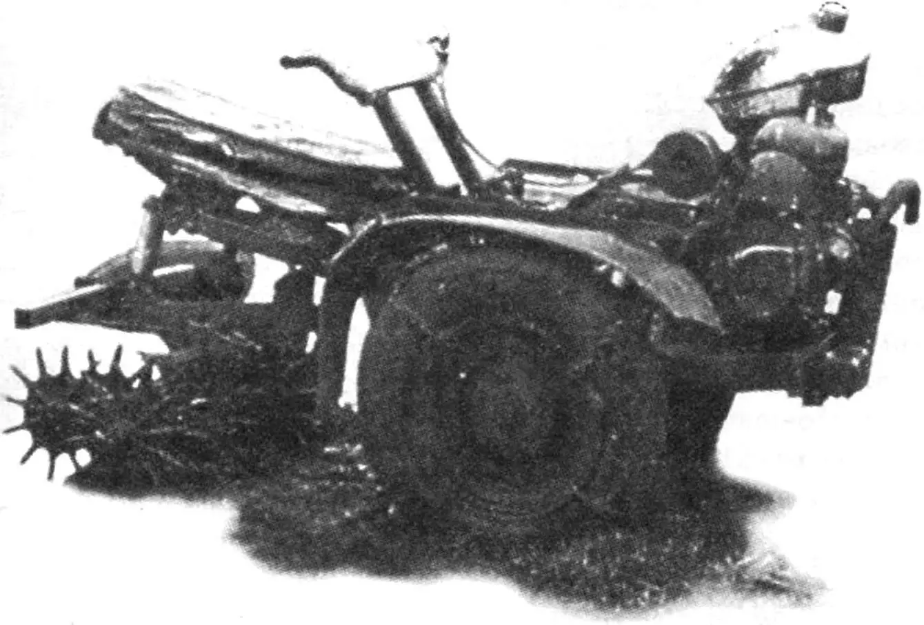
I set myself the goal of making a nimble, reliable, and compact walk-behind tractor. So that this mechanical assistant would work in the garden, plow the vegetable garden, cut beds, plant potatoes in the home field, weed seedlings, and harvest… And most importantly, so that I could operate this equipment while sitting in a comfortable chair without experiencing fatigue.
I won’t say it happened right away, but the idea succeeded. For three years now, my homemade walk-behind tractor (MB) has been serving, as they say, faithfully and truly. I named it “Pony.” For its endurance, for its reliability. The only thing it requires is gasoline.
My walk-behind tractor has no sprockets with drive chains at all, which are quite characteristic of many homemade agricultural machines. Instead, a V-belt drive with gear ratios of 1:2.2 and 1:1.5 works reliably, performing the functions of both a clutch mechanism and a tensioning unit. Moreover, its practical implementation differs noticeably from the original technical solution considered in “Modelist-Konstruktor” No. 7 for 1991 (article “Clutch on… belts“). Moreover, in “Pony,” the main reducer itself, which is rotary, acts as the regulator of clutch force (V-belt tension).
Among other features of my walk-behind tractor, I would also like to note the rigid mounting of half-axle couplings on the output shaft of the main reducer.
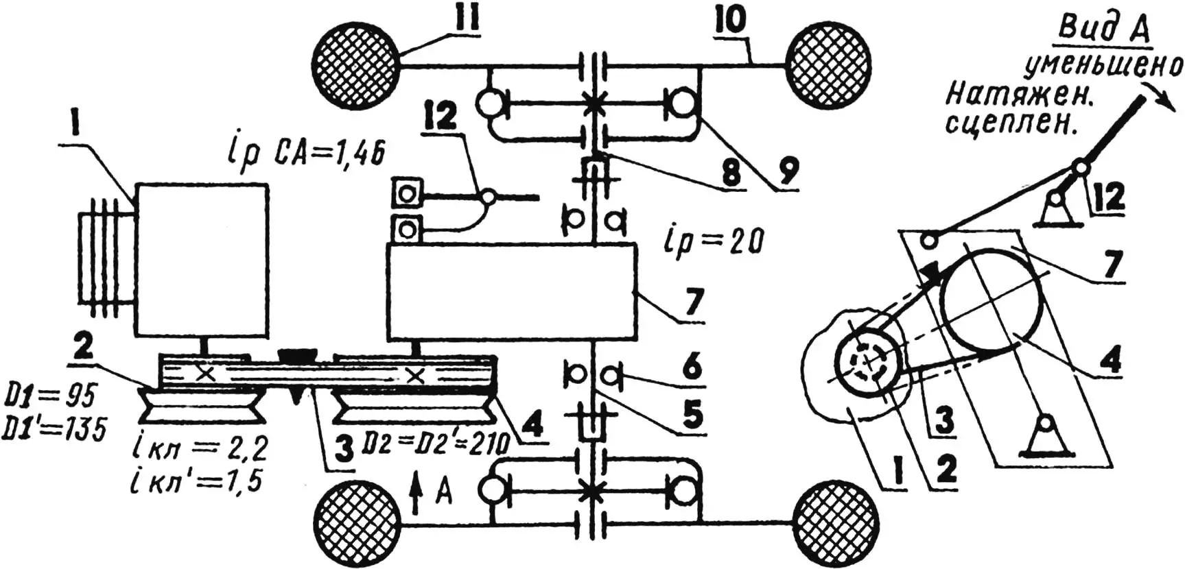
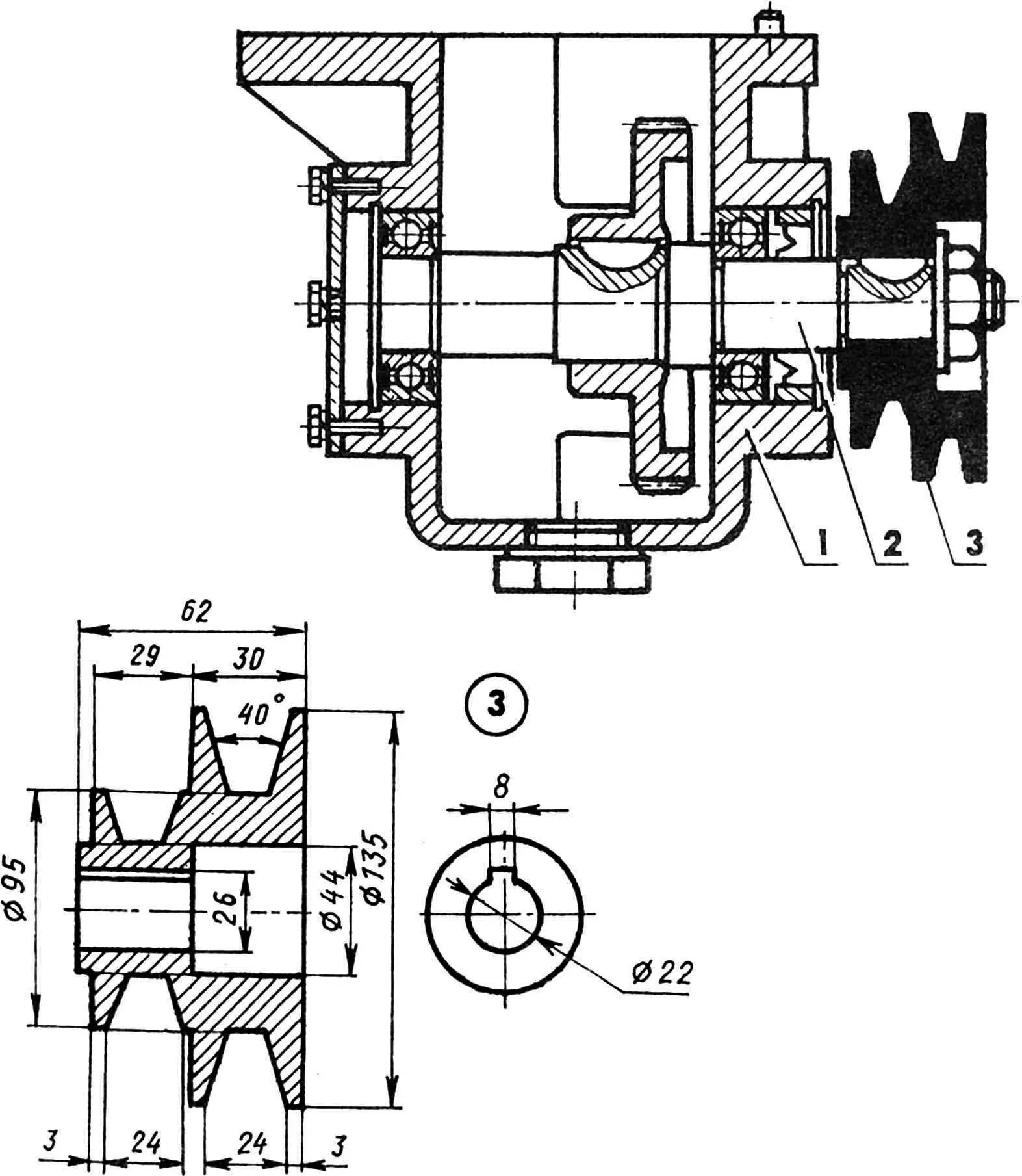
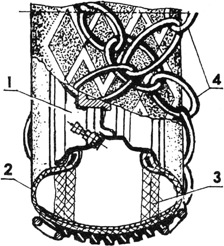
1 — power unit ТД6М, modernized; 2 — drive pulley, two-speed; 3 — V-belt В24-1303 (from bus fan drive); 4 — driven pulley, two-groove (from grain harvester); 5 — built-in reducer output shaft; 6 — ball bearing 206 (2 pcs.); 7 — main reducer (from irrigation system, modernized); 8 — half-axle coupling (2 pcs.); 9 — overrunning clutch (from agricultural machinery, 2 pcs.); 10 — wheel (from “Zaporozhets” car, modernized, 2 pcs.); 11 — tire (from “Moskvich-412” or “Zhiguli” cars with shock-absorbing filler and anti-slip chains, 2 pcs.); 12 — clutch lever with guide.
Since even during design I set myself the goal of making everything simpler and more reliable, in the MB I had to abandon the power unit (PU) Т-200М — there were too many excesses in it, in my opinion. The search for the most suitable PU led to a stationary and small-displacement ТД6М engine with a power of 7 hp, which is a modern modification of the well-known ПД-8 from time immemorial with a typical demultiplier.
The compactness of this PU, its air cooling, and built-in reducer with a gear ratio of 1:1.46 played an important role. However, a number of changes were made to the ТД6М itself.
First of all, I had to replace the standard cylinder with head with moped ones (from my Т-200М). And as a result — the engine power increased to 12 hp.
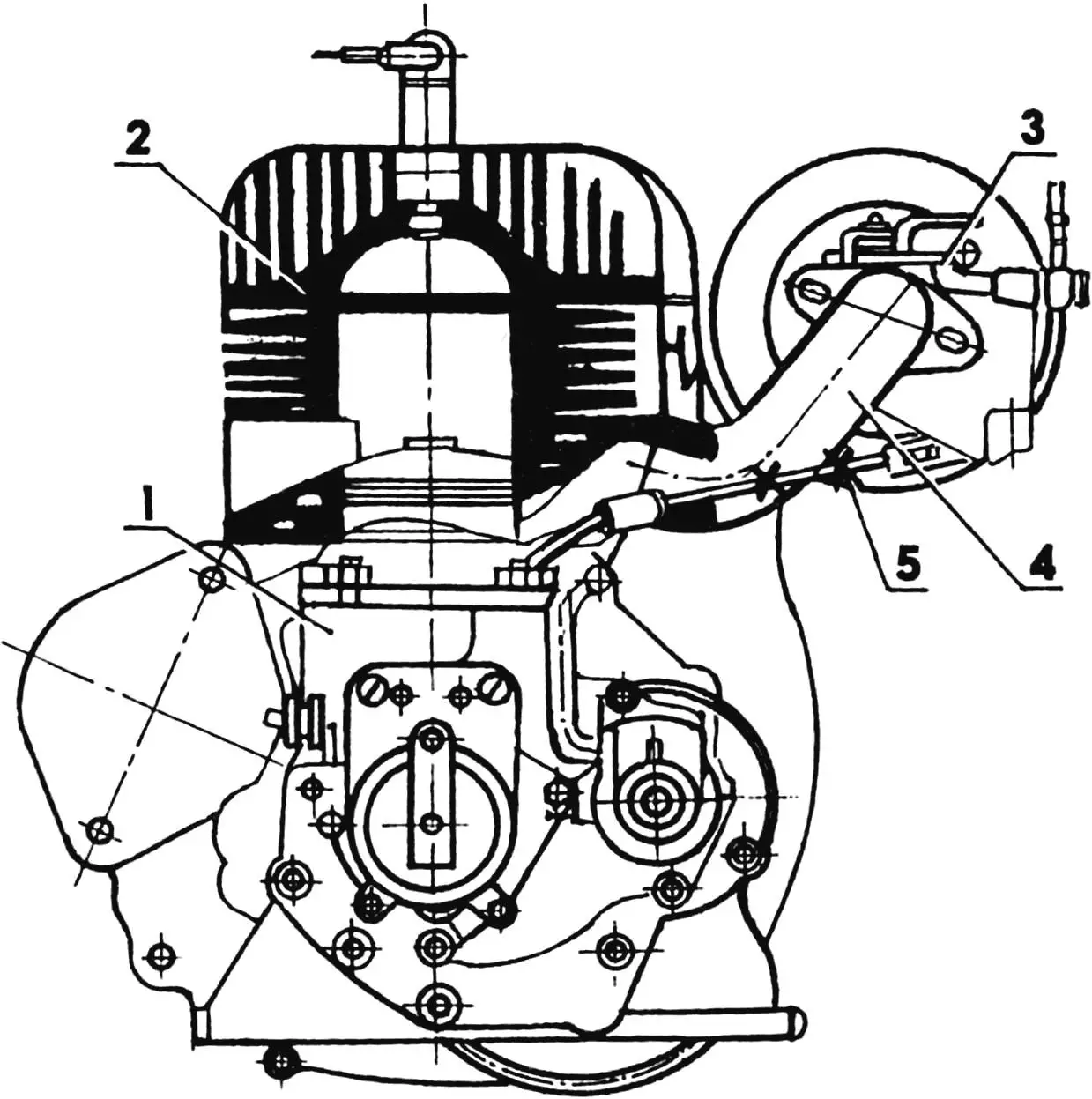
1 — base engine; 2 — cylinder with head and intake manifold base (from Т-200М engine); 3 — base carburetor; 4 — base intake manifold (“truncated” and welded); 5 — speed regulator linkage (removed as unnecessary).
The carburetor on the engine remained the same (К16Л), as it is reliable and simple to maintain. But connecting it to the moped cylinder required some effort. Those who decide on a similar design will have to repeat after me in the same sequence the following operations.
First, cut the intake manifold at the cylinder base and, turning the cut-off part of the manifold so that the carburetor is horizontal, mark both cuts. Second, remove these parts from the cylinder, carefully align them (using the marks as a guide), and, clamping them in the required position, weld them, then remove the scale formed inside the manifold. In addition, smooth out all irregularities inside the manifold first with a round file, then with the help of a small device described in its time in the “Modelist-Konstruktor” magazine. The device is based on a metal 8-mm tube 150 mm long. At its end, a 15 mm deep cut is made with a hacksaw, into which sandpaper folded in half with the abrasive layer outward is clamped. Inserting the device with the tube-shank into an electric drill chuck, the surfaces are processed first with coarse sandpaper, then fine.
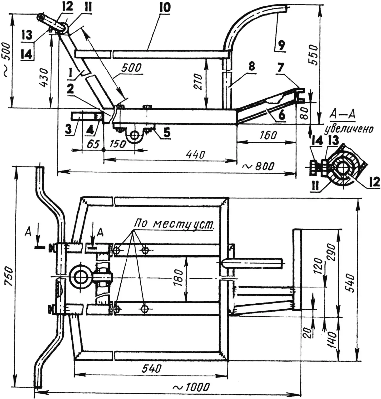
1 — steering post (2 pcs.); 2 — base frame (steel tube 60x40x5); 3 — bushing (steel tube 80×20, L40); 4 — welded pin (steel rod Ø40); 5 — bearing housing 206 (2 pcs.);
6 — engine frame beam (steel channel 6, 2 pcs.); 7 — engine frame stringer (steel channel 5); 8 — post (steel tube 30x30x4, 2 pcs.); 9 — fuel tank bracket (steel tube 32x32x4); 10 — fender bracket (steel angle 25×25); 11 — handlebar crossbar (steel tube, dimensions as required); 12 — handle (from bicycle, 2 pcs.); 13 — nut М8 (2 pcs.); 14 — bolt М8 (2 pcs.).
The modernization of the PU does not end with cleaning the intake manifold. It is required, after disconnecting the speed regulator linkage (it is not needed in this design), to replace the standard drive pulley with a new one, turned to match the belt profile decided to be used.
The drive pulley is two-groove, with different diameters. When operating the walk-behind tractor, this allows (by switching the belt from one to the other) to obtain two travel speeds: transport (12 km/h) and working (4.5 km/h).
After installing the homemade pulley in place, filling the reducer with oil, and connecting the moped (from the same Т-200М) muffler, the modernization of the ТД6М power unit can be considered complete. However, to more fully realize the technical capabilities built into such a PU, an appropriate main reducer is also needed: strong, reliable, and compact. And most importantly — it should have a gear ratio as close as possible to the calculated one, determined during the development of the walk-behind tractor’s kinematic diagram (in my case 1:20).
1 — built-in reducer housing; 2 — output shaft; 3 — V-belt drive pulley, drive, two-speed, homemade (cast iron СЧ20 or aluminum alloy АЛ8).
For the MB “Pony,” a reducer from a domestic irrigation system, usually working in tandem with the “Druzhba” power unit, was perfect. The refinement of this reducer was simple: I got rid of the “capricious” bevel gears by abandoning reverse gear, which “eats” so much needed “horsepower” (if necessary, the MB can easily be rolled back manually).
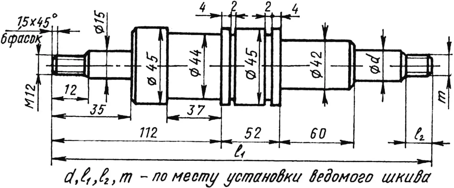
Now in the main reducer — a homemade shaft with a driven two-groove pulley 210 mm in diameter (from a grain harvester). To install such a shaft, a corresponding hole for the seal had to be made in the reducer cover.
The highlight of the MB transmission’s power section is that the main reducer is not rigidly attached to the frame, but freely “rolls” along the drive shaft. And a special linkage with a handle, which performs the function of a drive belt tensioner, prevents it from rotating, allowing the walk-behind tractor to start smoothly and, if necessary, stop just as easily.

The simplicity of the resulting design undoubtedly affects the high reliability of the MB “Pony”: over more than three years of intensive operation — not a single significant breakdown. Well, if failures do occur, it’s due to the engine’s starting device, where, as it turned out, an unreliable spring is installed (so it makes sense to take care of a spare in advance or generally get a “starter” made by another factory).
However, let’s return to considering the design features of the main reducer. Two bearings 206 connect its drive shaft to the frame. Moreover, the ends of this shaft, entering the wheel half-axles, form a single whole with them thanks to bolted connections. At the ends of the half-axles are overrunning clutches taken from agricultural machines, to which the wheel discs are attached.
I had to work quite a bit on choosing the wheels, because with the low mass of “Pony,” they must create optimal traction with the soil. I tried all kinds (from solid metal ones to pneumatic wheels with different types of ground grips), until I settled on a composite design I came up with myself — with installation on a wheel disc from a “Zaporozhets” car of a soft radial tire with a universal tread (from “Zhiguli” or “Moskvich-412”) and filled not with compressed air, but… rubber. More precisely, four side half-rings cut to the tread from two old “diagonal” tires.
From my own experience, I know how difficult it is to push such elastic blanks inside each working tire, “beaded” on the disc. You can’t do without a hefty hammer, a “crowbar,” and a blunt chisel.
On each wheel of the walk-behind tractor, there is a large-link chain installed with diagonal intersections. It performs a double function: it prevents the tire from rotating and serves as a ground grip. With wheels resembling the wrapped footcloths of bast shoes, “Pony” never gets stuck. However, it performs maneuvers on asphalt with much less ease than, say, in the field. Therefore, when using the MB as a vehicle on good roads (especially when there’s solid asphalt or concrete all around), I change the “bast shoe” wheels to pneumatic ones.
The steering control on “Pony” is of the motorcycle type. On the left side of the handlebar is the “throttle” lever. A fuel corrector lever from “Tula” is used, which allows fixing the “throttle.” The “ignition” toggle switch is also located here (it also serves to stop the engine). Below is the clutch engagement lever. And that’s it: no more levers or pedals.
A soft seat from the “Tula” moped is adapted for the driver. Located on the coupling unit, it allows choosing a comfortable seating position for different types of work.
1 — base frame; 2 — main reducer housing; 3 — ball bearing 206 assembly (2 pcs.); 4 — joint for working speed; 4 — joint for transport speed; 5 — guide with adjusting coupling; 6 — clutch lever; 7 — heel; 8 — stop-fixator.
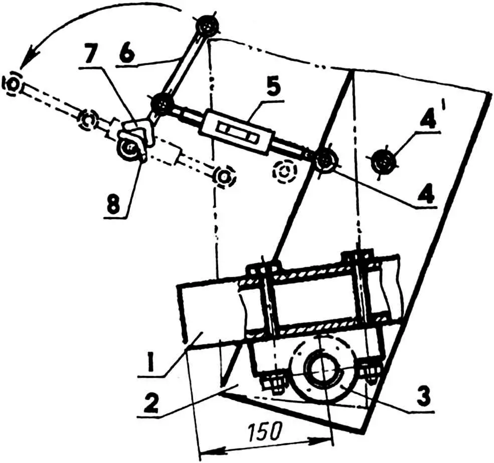
The coupling unit itself, performing many additional functions, is a linkage with a welded 8 mm thick iron strip. On the latter — mounting for the seat, and next to it — a cardan shaft flange with internal splines. The linkage is attached to the frame through a rotary device and can rotate left-right and around its axis. The first allows the driver to control the MB, and the second significantly facilitates making turns when using “Pony” with a cart. The unit for adjusting the tilt of attached implements is also located here, which is very important, in particular, for adjusting the vertical position of the plow.
The coupling unit also houses the driver’s footrests, plow mounting, and plowing depth adjustment lever, a box for keys and tools.
Now about starting the power unit in cold or heat. The essence of “winter” recommendations is that first you should “drown” the float until gasoline flows, and only then quickly start the engine. After starting, you need to press the float again. After holding it “drowned” for about 10 seconds, you can release it — the engine will no longer stall.
In summer, everything must be done exactly the opposite. As soon as the engine is shut down, you should immediately close the fuel supply valve to the carburetor. Starting (especially in heat) is recommended to begin with the valve closed. However, such practice is justified only when there are no fuel leaks from the carburetor. Since the engine starts on the first try, the valve should be opened immediately.
1 — disc (from “Zaporozhets” car, modernized); 2 — tire (from “Moskvich-412” or “Zhiguli” cars); 3 — filler; 4 — ground grips.
Like a good children’s construction set, “Pony” takes on different forms during different types of work. For example, during plowing, it’s a three-wheeled vehicle. During hilling — there’s a resemblance to a lunar rover: two drive wheels in front, and behind, the elements of a needle cultivator flicker… By the way, about the cultivator. If earlier, during plowing and potato planting, a support wheel followed behind the plow, compacting the soil, then after replacing it with a cultivator “hedgehog,” the soil is not compacted but additionally loosened. And for inter-row cultivation of root crops and other row crops, the needle cultivator is indispensable. The driver, sitting on the seat, presses with all his weight on the “hedgehog” elements, and they, penetrating into the surface layer of soil, destroy weeds.
When harvesting potatoes, two support wheels are attached to the coupling unit, and “Pony” becomes a kind of mini-tractor, to which a special digger is coupled, made from a cultivator blade with 10 mm diameter steel rods welded to it. The support wheels are from the same “Tula” moped, with levers made from elements of an old harrow.
Potato planting is done mechanically “under the plow.” The exception is perhaps the manual placement of seed tubers. I start from the middle of the plot, pass the first furrow with the plow, and plant potatoes in it at a distance of 0.25—0.3 m from each other. Then the next pass. Two furrows turn out to be filled, and seed tubers are thrown into the third, and so on. The distance between rows of planted potatoes is 0.65 m, which is necessary for subsequent mechanized inter-row cultivation.
The plow is made from a standard plowshare. The stand is cut, fitted to the installation location, and welded. The share-moldboard is from a cut and slightly unfolded steel tube.
A transport cart with a capacity of 700 kg is attached to the coupling unit at two points.
The MB frame is welded from sections of rectangular steel tube 60x40x5 mm, square tube 30x30x4 mm, and steel angle 25×25 mm. The fuel tank is from the “Riga-11” moped.
“Modelist-Konstruktor” No. 12’99, K. PANASYUK
Recommend to read
 WALK-BEHIND-TRUCK
Offer to readers design their new walk-behind. But before describing it, a little background. Village life is hard their daily monotonous work in summer and winter, rain and snow...... AND WILL LOOP HIDDEN
Offer homebrew. engaged in the manufacture or have manufactured furniture with doors mounted on piano hinges to replace them on domestic furniture, because the presence of piano hinges,...
