Everyone, of course, has their own concerns. For example, problems associated with the mechanization of harvesting, say, peppermint, are unlikely to seriously interest me. It’s a different matter with potatoes, which in terms of their importance and value are not without reason called second bread. How difficult it is! It’s not enough to plant and grow this troublesome crop. After all, the tuber harvest must be dug up within the time allotted by nature. And bring it home from the field without loss. Where is the technology?
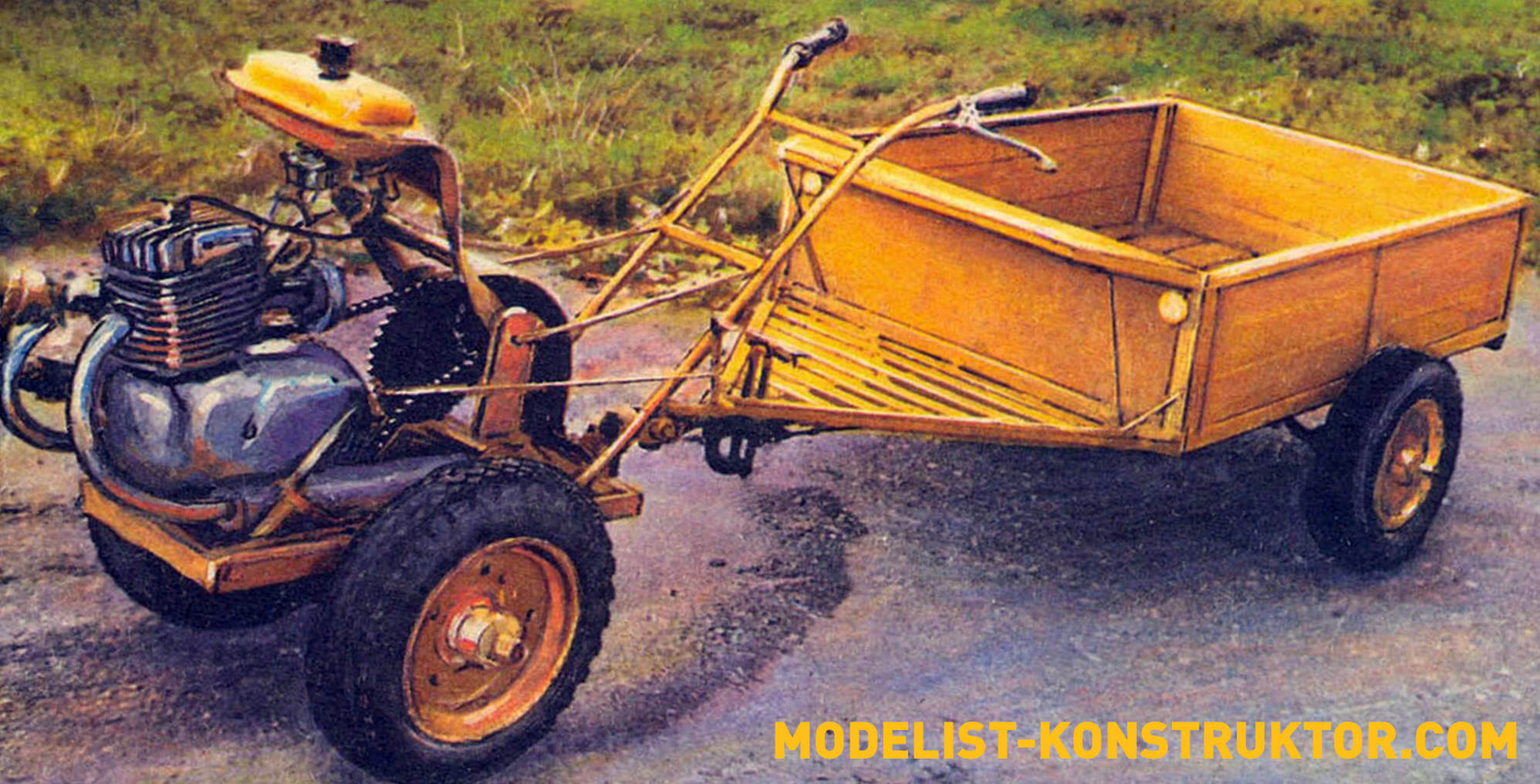
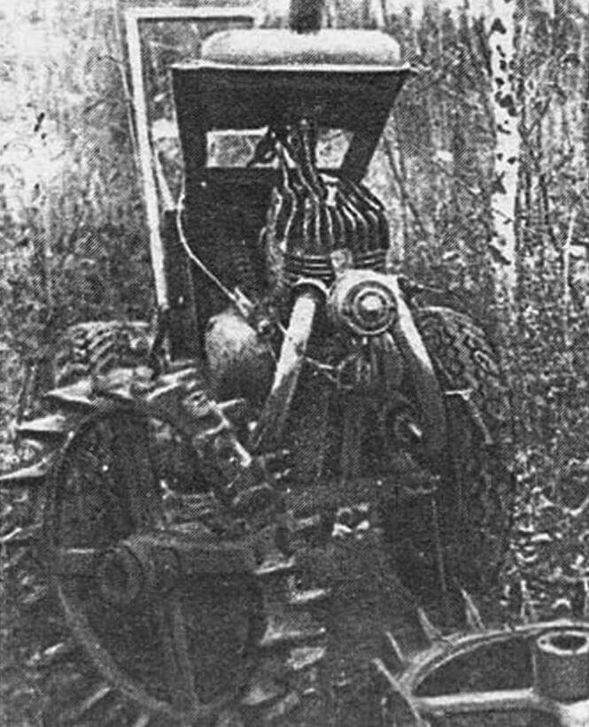
Having looked around, I fixed my gaze on the old Voskhod-3 motorcycle, which had been used for a long time. Immediately (like, probably, many who found themselves in a similar situation) a decision arose: to be this veteran (fortunately, the engine is intact) as a motorcycle assistant while harvesting potatoes.
The kinematics and the entire design as a whole are quite simple. Based on the need to reduce the speed to optimal (harvesting potatoes is not a motor rally), an intermediate shaft with two sprockets was introduced into the kinematic scheme. Moreover, in the first stage of torque transmission it was possible to completely leave the “original” sprockets from the motorcycle. But “for the purpose of unification” they were replaced with those suitable for agricultural machinery (especially since there was such an opportunity). As for the second stage of the PR-19.05 chain drive, the ratio of the teeth of the sprockets (taken again from agricultural machines) is 1:4.5.
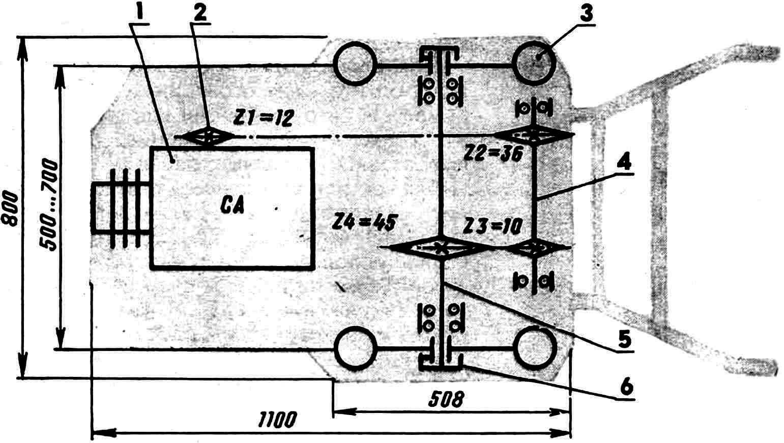
1 — power unit (Voskhod-3 motorcycle engine, modified, with forced air cooling), 2 — PR-19.05 chain drive sprocket, 3 — main or plow transport wheel (2 pcs.), 4 — intermediate shaft , 5 — wheel shaft, 6 — coupling coupling (2 pcs.).
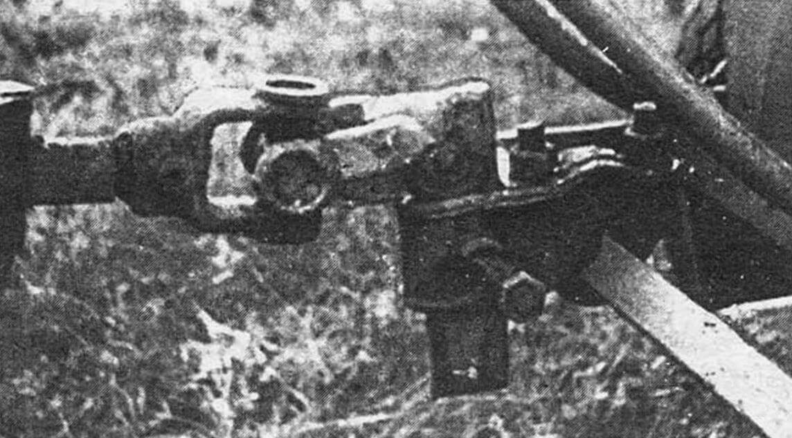
There is no differential (due to its scarcity and high cost). Both wheels are driven. And to make it easier to control when turning, a clutch coupling is provided. Due to this, some freedom of rotation of the wheels relative to each other and the axis of the walk-behind tractor is achieved. In essence, a small backlash is introduced (see illustration). Moreover, instead of two, you can limit yourself to one coupling.
It is possible to release the wheel from engagement with the shaft. After all, it is enough to install the coupling coupling with the reverse side (without the protrusion) to the slot on the hub and additionally balance the cart along the line of traction, as you get one drive wheel instead of two. And immediately the old problems disappear.
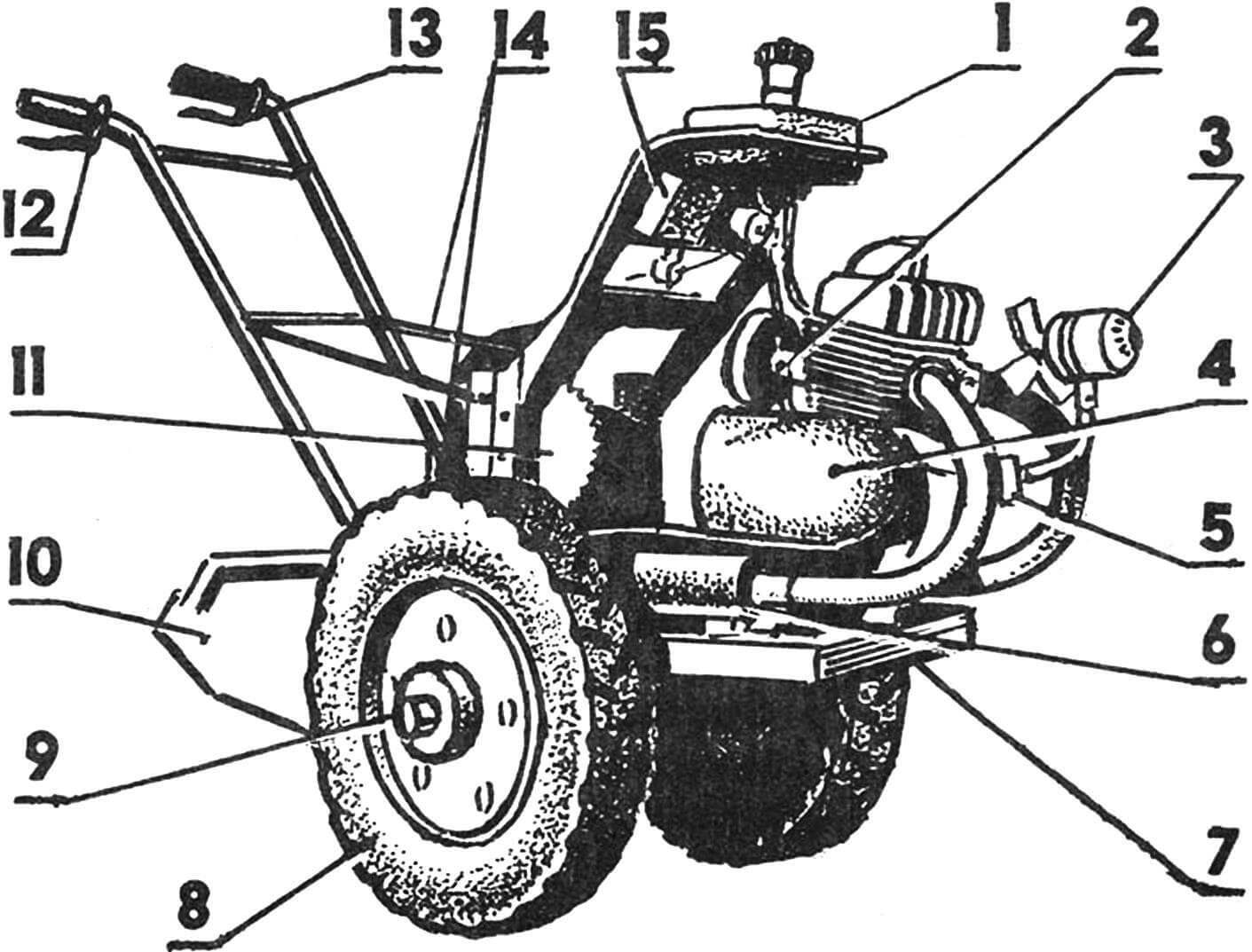
1 – fuel tank, 2 – muffler, 3 – forced air cooling fan, 4 – power unit (motorcycle engine), 5 – bracket with rectifier for powering the fan, 6 – muffler, 7 – frame, 8 – transport wheel (2 pcs. .), 9 — coupling coupling (2 pcs.), 10 — mounted working implement (plow, potato digger, etc.), 11 — intermediate shaft gear (2 pcs.), 12 — throttle handle, 13 — clutch handle , 14 — tie rods, 15 — instrument panel.
A carefully sorted, tuned engine will not cause any trouble. Moreover, to increase reliability, it has undergone a small (but, as practice has shown, very valuable) modernization. The essence of the latter is to install a mini-system of forced air cooling. This is an electric motor designed to operate from a 12-volt DC network (used in cars), with a simple homemade impeller. This fan is mounted on a special bracket. And it is connected to the walk-behind tractor engine generator through a diode bridge and a capacitor (see diagram).
Wheels are the most common: 5.00-10”. Perfectly suited for agricultural machinery. By the way, they also provide dustproof self-aligning ball bearings. For work on heavy soils, metal wheels with lugs are used. These can be made using numerous publications (see, for example, No. 8’90, 10’91). But it’s easier to use, of course, ready-made ones: from a ring harrow (see ill.). The throttle and clutch handles are suitable for motorcycles. From Voskhod-3 and kickstarter, exhaust pipes. The throttle and clutch cables have been lengthened.
The walk-behind tractor frame is welded. Made from scraps of steel angle 36×36 mm. In its front part (strictly along the axis of the walk-behind tractor) it has welded racks for the engine. And in the rear, the linkage mechanism is attached to two M16 bolts. Turning. Not far from it there are holes (two each on the right and left, not shown in the illustration) for installing racks for the intermediate shaft. Moreover, the design of the latter is quite simple. Let us only note that this is a 300 mm section of a 40×64 mm angle with two holes on its wide part (for the intermediate shaft bearing), welded to a steel base plate (8 mm St3 with dimensions 40×90 mm).
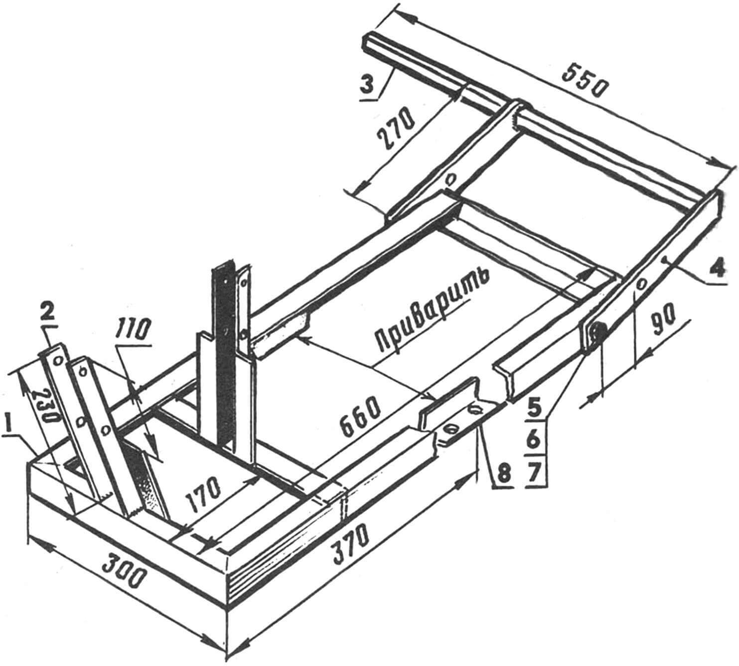
1 — frame with cross member (welded structure made from angle steel 36×36 mm), 2 — rack for the engine (230 mm piece of angle steel 36×36 mm, 4 pcs.), 3 — beam for attaching mounted work tools (square rod 22 ×22 mm from St5), 4 — rotating spar of the linkage mechanism (270 mm strip from St3 with a section of 40×8 mm, 2 pcs.), 5 — axle bolt M16 (2 pcs.), 6 — washer (4 pcs. ), 7 — M12 nut (4 pcs.), 8 — bracket for fastening the bearing assembly of the wheel shaft, welded (200 mm piece of steel angle 36×36 mm, 2 pcs.).
The mounting locations for the wheel shaft bearings are located at the bottom in the middle part of the frame side members. They are nothing more than a 200 mm steel angle 36×36 mm, with corresponding holes for bolted connections.
The rotary mechanism of the hitch, as can be seen from the illustrations, consists of two spars of rectangular section 40×8 mm, M16 axle bolts and a beam for attaching the working tools themselves, the fixed elements of which are clamped in serial sockets (internal size 46×17 mm, conditionally not shown) from tractor cultivators. Moreover, each of the side members has several Ø 16 mm holes equidistant from each other (not shown), intended for U-shaped fastening brackets with M16 threads at the ends. At their other end, the latter are attached to the stands of the intermediate shaft, the manufacture of which, by the way, as well as the installation of sprockets and bearings on it, is not particularly difficult.
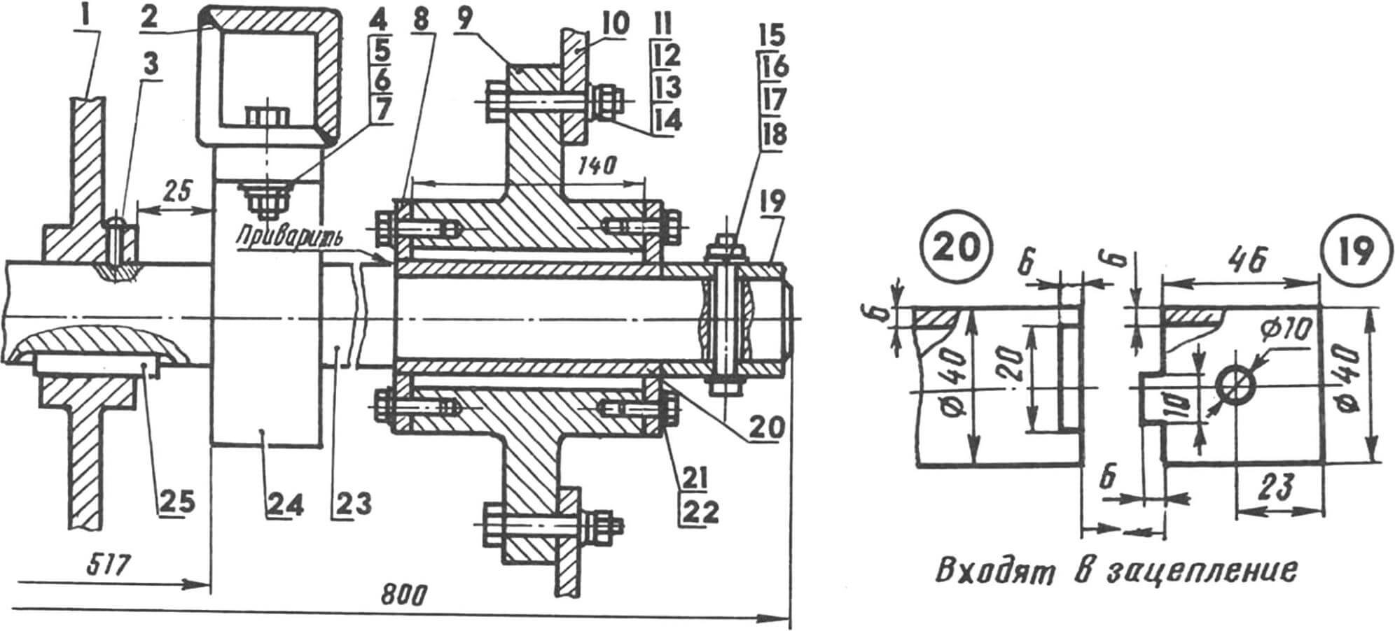
1 — sprocket Z4-45 (from decommissioned agricultural machinery), 2 — frame with welded bracket (steel angle 36×36 mm), 3 — M6 set screw with a semicircular head, 4 — M12 bolt (2 pcs.), 5 — washer ( 2 pcs.), 6 — Grover washer (2 pcs.), 7 — M12 nut (2 pcs.), 8 — hub cover (from decommissioned agricultural machinery, 2 pcs.), 9 — hub (from decommissioned agricultural machinery), 10 — wheel disk 5.00=10″, 11 — M8 bolt (4 pcs.), 12 — washer (4 pcs.), 13 — Grover washer (4 pcs.), 14 — M8 nut (4 pcs.), 15 — bolt M10, 16 – washer, 17 – Grover washer, 18 – nut M10, 19 – coupling coupling (from a 52 mm section of pipe 40×6 seamless cold-rolled steel), 20 – coupling sleeve (from a 152 mm section of pipe 40 ×6 seamless cold-rolled steel), 21 — M6 bolt (8 pcs.), 22 — Grover washer (8 pcs.), 23 — wheel shaft (Steel 45), 24 — bearing unit with self-aligning ball bearing (from the SK-5 combine) , 25 — prismatic key.
Wheel shaft with components and parts installed on it.
The fastening of hubs and couplings is special here. By transmitting torque, this joint introduces a slight play – a “substitute” for the differential, or completely opens the kinematics, making wheel rotation free.
As practice has shown, it is enough to perform such a clever fastening on one wheel, and fix the second one rigidly on the shaft using any of the well-proven methods. For example, using a through bolt with a nut. The keyed connection, reinforced with a fixing (set) screw, also holds perfectly.
In any case, one of the hubs remains a rather complex design, with two covers and a coupling sleeve. But the task will be significantly simplified if you can get a ready-made hub from agricultural machinery. Then all that remains is to slightly bore the central hole in the covers to a diameter of 40 mm and weld on one side (facing the walk-behind tractor frame) a coupling sleeve made from a 52-mm piece of steel pipe with a wall thickness of 6 mm, which has a rectangular end at the end opposite to the axis of the machine cutout This is where the protrusion-hook will go.
A coupling coupling is made from a section of the same pipe; It is attached to the wheel shaft using a bolted connection. So, if necessary, the wheel movement can be made free in just a few minutes. It is enough just to unscrew the nut, pull out the bolt and, turning the coupling 180°, install it in place, followed by rigid fixation on the shaft.
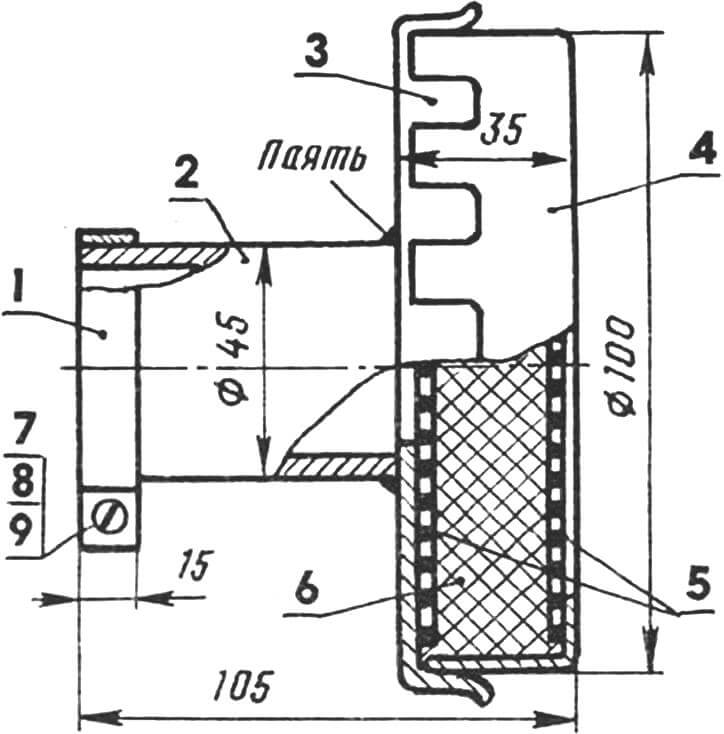
1 — clamp (0.7 mm rolled thin-sheet steel), 2 — sleeve (70 mm piece of pipe 45×2.5 seamless hot-rolled steel), 3 — lid (from a tin can), 4 — body (from a tin can) , 5 — wire mesh (2 pcs.), 6 — filler (nylon thread impregnated with machine oil), 7 — M5 bolt with a semicircular head, 8 — Grover washer, 9 — M5 nut.
Homemade air purification filter . It is made from a piece of steel pipe, wire mesh and a tin can (see illustration). And as a filler, oil-soaked nylon thread will work perfectly in it. The air cleaner is installed using a steel clamp, securely tightened with an M5 bolt and nut.
The muffler is also homemade. It is based on a section of steel pipe, in which a kind of “labyrinth” is created for the exhaust gases from 2-mm steel partitions. Moreover, they can be attached in different ways.
Two methods of fixing partitions can be considered the most successful. The first is by “stringing” it onto a steel rod-stud with nuts. But for this it is necessary that the partitions have a central hole for such fastening. The essence of the second method is in grooves made in the pipe body – the muffler body, into which partitions are inserted and then welded along the outer surface, the manufacturing radius of which is increased taking into account the thickness of the body wall. With the exception, however, of the last partition disk.
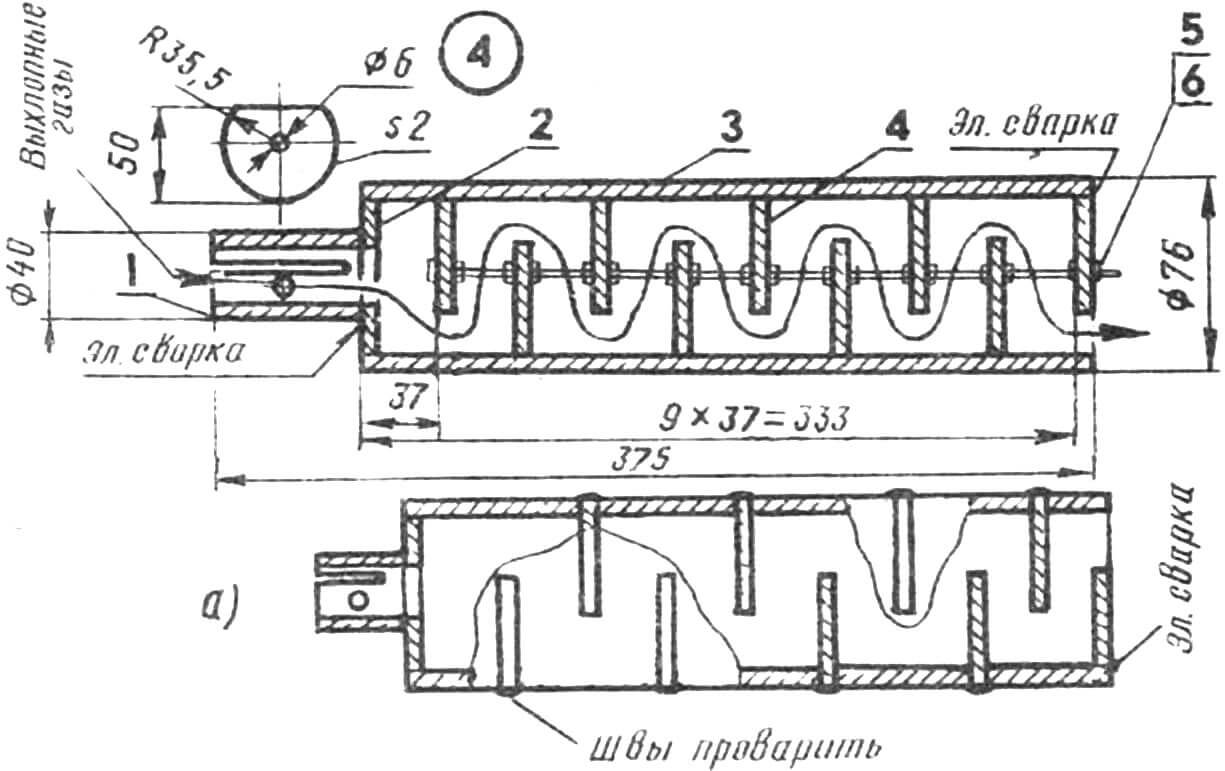
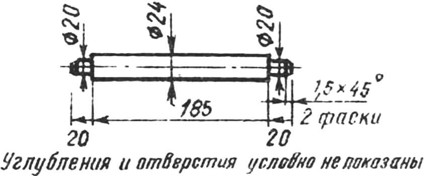
1 — bushing (40 mm piece of pipe 30×2.5 seamless hot-rolled steel; hole and slot at the installation site), 2 — welded washer (2 mm St3), 3 — body (335 mm piece of pipe 76×2, 5 seamless cold-rolled steel), 4 – partition (2 mm St3, 9 pcs.), 5 – 312 mm rod (hot-rolled round steel), 6 – M6 nut (18 pcs); a – option with mortise partitions with R=38 mm (for the latter R=35.5 mm).
A sleeve welded at the front is used to connect the muffler to the exhaust pipes. In fact, this is an ordinary piece of pipe with a slot and a hole, the dimensions and exact location of which are at the installation site.
The remaining structural elements of the walk-behind tractor, their manufacture and fastening, I think, will not cause any difficulties for anyone. If, of course, you focus on the illustrations presented.
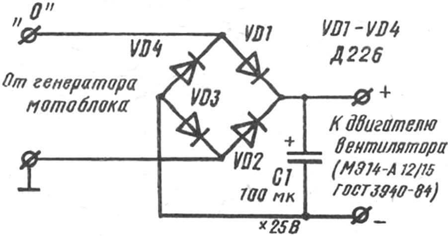
A small-sized electric motor of type ME14-A12/15 (GOST 3940-84) is ideally suited for the fan. But you can use any other one, designed to be powered from a 12V DC network. In our case, as already noted, it works from a homemade rectifier (see diagram) connected directly to the walk-behind tractor generator. The diodes with a capacitor are mounted in a plastic case and placed together with the fan itself on a special bracket.
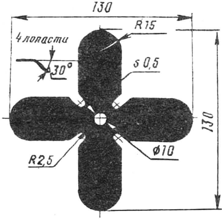
As the long-term operation of the walk-behind tractor has shown, the cooling system used in its design is much more efficient than that found on motorcycles. Moreover, the gain here is obvious at all times of the year. True, in winter, in order to maintain the optimal temperature regime of the engine, it is advisable to install on the fan not a four-blade, but a two-blade impeller, the manufacture of which is not much different from the one shown in the illustrations.
Any fuel tank can be used. Including homemade ones. Fuel from it is supplied by gravity. The tank is attached to the stands of the intermediate shaft – steel angles on a curved steel strip with a cross-section of 40×4 mm (St3). The bend creates additional rigidity and fits well into the layout of the entire structure as a whole. The same plate serves as the basis for installing an instrument panel and turn signals on it (when driving with a towed trolley, not shown).
The steering wheel is practically no different from those that have been repeatedly published in descriptions of home-made structures under the heading “Small mechanization”. These are the same two pipes of a suitable cross-section, bent accordingly, with the “gas” (right) and clutch (left) handles attached to them. To give greater rigidity, both pipes are connected together by the upper and lower crossbars. Moreover, the material for the manufacture of the latter is… the same pipes. The steering wheel is attached in its lower part with bolts and nuts directly to the walk-behind tractor frame.
It is advisable to install the brake lever on the left of the steering wheel, slightly below the lower crossbar. And next to it is the gear shift lever (pedal). So that they would be convenient to use even when combined with a trailed trolley.
And a few more features. The steering wheel in its middle part is fastened to the upper part of the intermediate shaft stand using round tie rods with a threaded connection at the ends (for better strength). And the KET switch and ignition coil are located under the fuel tank, behind the dashboard. A chain tensioning device is also provided.
The design of the coupling is shown in the illustrations. Well, how to do it requires a special conversation.
The coupling device (hitch) will not let you down. After all, it is performed on the basis of ready-made parts that have a large margin of safety (universal drive head, hitch pin), and an equally reliable home-made trailer (trolley) swivel unit. The latter, in turn, consists of two coaxial thick-walled steel pipes, the diameters of which are selected in such a way that the surfaces in contact with each other work like an angular contact sliding bearing. In addition, the inner tube is also a rotating axis. And the outer one is a drawbar, which not only serves to transmit traction force to the trolley, but also provides freedom of tilt of the latter relative to the axis of the walk-behind tractor (to the left or to the right).
The front end of the inner tube is welded to the gimbal head. On the rear there is an M36 thread for taking out play in the longitudinal direction and correspondingly attaching it to the welded cross member of the trailer frame. And one more feature. To prevent rotation in the vertical plane, as well as to prevent the hitch from falling over when turning, two horizontally located fingers of the crosspiece are welded to the horizontal fork of the cardan head.
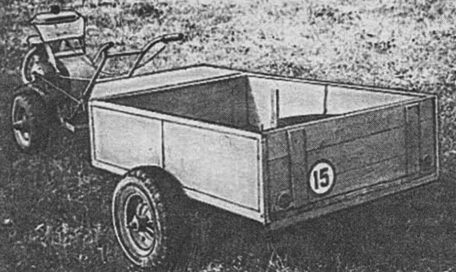
The frame of the trailed cart (see ill.), thanks to the inclusion of triangular (and this, as is known, the most rigid figure) elements in it and the use of a steel angle as a structural material, turned out to be very, very reliable. Its rectangular part is sewn up with clapboard, forming the bottom of the noose. But you can also use 6 mm steel sheet here. Four upward-facing 350 mm angle steel posts are welded to the frame, serving as the basis for attaching the sides. And they, in turn, can be made from both boards and steel sheets of appropriate thickness. The tailgate is made rotating and folds down. With fastenings and clamps similar to those used on trucks.
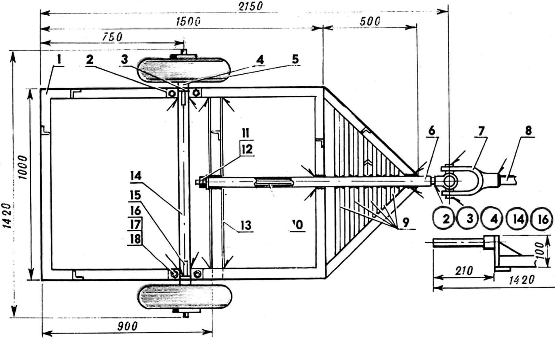
1 – welded frame (from steel angle 40×40 mm), 2 – thrust bearing (10 mm strip size 150×40 mm, St3, 2 pcs.), 3 – bracket (10 mm plate 100×40 mm, St5, 2 pcs.), 4 — axle shaft (Steel 45, 2 pcs.), 5 — wheel 5.00=10 assembled (from decommissioned agricultural machinery, 2 pcs.), 6 — drawbar (1200 mm section of 45×4 steel pipe seamless cold-rolled), 7 — cardan head (from decommissioned agricultural machinery), 8 — hitch pin (from agricultural machinery), 9 — welded poly (pieces of steel angle, 5 pcs.), 10 — rotary axis of the drawbar (hot-rolled round steel Ø 36 mm or a piece of steel pipe 36×6), 11 — M36 nut (2 pcs.), 12 — washer, 13 — welded cross member (a piece of steel angle 40×40 mm), 14 — spacer axis (hot-rolled round steel Ø 40 mm) , 15 — gusset (10 mm St3, 2 pcs.), 16 — M20 nut (4 pcs.), 17 — Grover washer (4 pcs.), 18 — M20 bolt (4 pcs.).
The seat is also reclining. Mounted at the front on two rotating triangular brackets made of 10 mm steel rod.
It is advisable to provide a rotating parking support at the head of the frame (bottom). How this was done, for example, in the design, drawings and descriptions of which were published in No. 3’90.
The rigid design of the wheel “suspension” matches the frame. There are no shock absorbers here, as can be seen from the illustrations. In the author’s deep conviction, they are not needed for work in the field. But the reliability of the entire trailer immediately increased significantly. For the same reason, a round steel rod with a diameter of 40 mm was used as a material for the manufacture of axis-springs. To slightly increase the clearance of the trailed trolley, the wheelchairs are installed on the brackets. They are welded to the bloodsters and reinforced with braids of 10-mm steel sheet.
As for the wheels of the trailer themselves, it is better to take them from written off agricultural machinery. Based on the practice, I dare to say: they will serve you perfectly. Moreover, such wheels are attached on the self -supporting ball bearings available in their hubs.
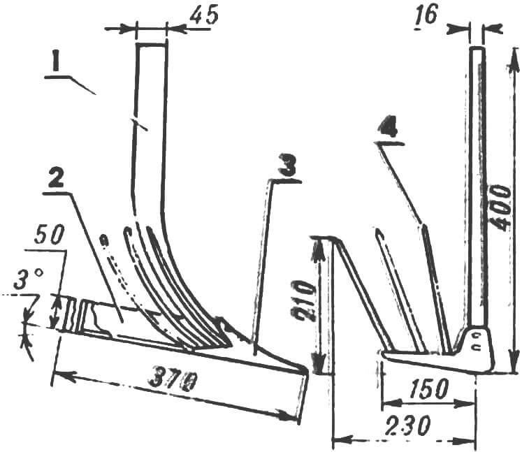
1-bipod (from the serial tractor cultivator), 2-field bar (a steel corner of 50 × 50 mm), 3-tip (trimmed paw of the cultivator), 4-a dentist (from garden foriles with a romance at an angle of 45 ° after welding to The tip of the lower end, 2 pcs.).
Cart-fluid hip can also be borrowed from agricultural machinery. Although a home -made design similar to published in No. 2’86 is quite suitable. But it is advisable to make a field bar not from 6 mm st3, but to use a 50 × 50 mm steel corner. And to weld it not at an angle of 5 ° to the horizon, but about 3 ° – then the potato -cutter goes through the field even.
For the best separation of tubers from the ground, you should also slightly increase the length of the tooth-rifle-rifle millimeters by 10 in both coordinates. Then the cigarette clinker will take the form shown in the illustration.
The rake (and without them – what harvesting suffering) can be easily made according to the drawings and description of the structure published in the fourth issue of the magazine for 1990. As, however, to equip your motorized carrier with a bulldozer dump (see ibid.). But to make a plow and harrow, focusing on the corresponding material printed in No. 10’91.
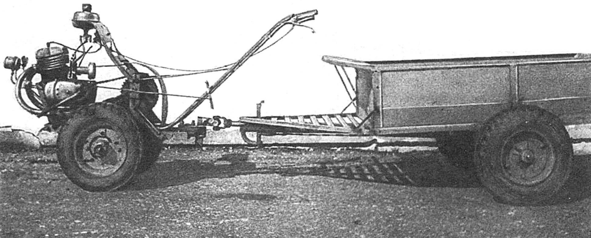
A two-wheeled walk-behind tract with a trailer of a cart-articulated cart with it is, in fact, a mini-tractor. Much can do this. Of course, if the design of the articulated units itself is quite compact and reliable, and the coupling has the required number of degrees of freedom and the proper margin of safety.
As the impassive time has shown, the mini-selkhozhomachin in question turned out to be just this: successful and reliable. Yes, and there is, in fact, to break here.
Technical characteristics of the walk -behind tractor
Dimensions (without the steering wheel of control and trailer), mm – 1100x800x1000
Track, mm – 500 … 700
Base of a walk -behind tractor with a cart, mm – 2130
Minimum turning radius with a cart, mm – 2150
Maximum speed during transportation of goods, km/h – 20
Working speed for plowing, digging potatoes, km/h – 3.5
Engine power (excluding its refinement), L.S. – 14
V. Soloviev, Republic of Mari El
Recommend to read
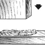 WITH COTTON — TIGHT
The surfaces are usually not only previously degreased, but cleaned with sandpaper to get the roughness that increases the strength of the connection. The same effect can be achieved if...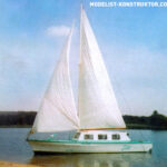 UNDER SAIL OR MOTOR
The motor-sailing vessel (SMS), which will be discussed, was built on the basis of the finished hull of an existing model of a torpedo boat, made on a scale of 1:4. I got the hull of the...
