RETRACTABLE LANDING GEAR RACING

RETRACTABLE LANDING GEAR RACINGAbout 190 km/h! This is a technical medium speed modern racing model with a powerful engine. Moreover, the maximum operating speed of the model exceeds 170 km/h, this is not the limit. Constantly improving miniature aircraft, athletes strive to further reduce the time of passage of a ten-kilometer distance. Before the Modeler, usually three ways: change the layout scheme, forcing the engine and improved aerodynamics models.

 
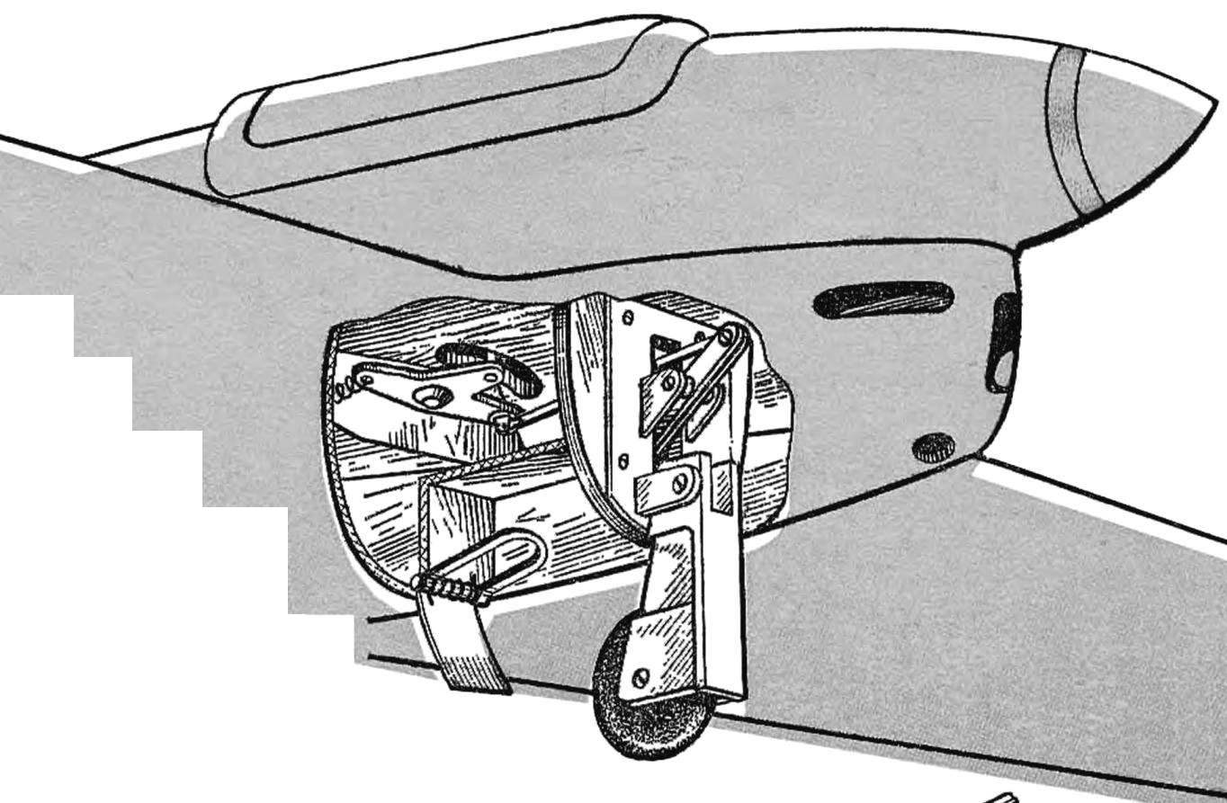
Significant share is the total aerodynamic drag. Removing from the model projecting parts, you can significantly reduce it. One of the few sites, greatly protruding beyond outline of the fuselage, is chassis. Prospective design retractable landing gear (Fig. 1) allows to achieve a result.
 
The mechanism of the landing gear is driven by a “floating” rocker control model. Its axis while attached to the wing (as usual) and the drive rocker mounted on the wing.
 
The kinematics of the lifting of the chassis legs is simple: when the centrifugal force acting on the model reaches a certain value, the cord stretches and rocking, overcoming the restraining force of its springs, thrust rejects the yoke and removes the rack. At the same time goes up and rear flap, closing the cavity of the fuselage.
 
Landing gear performs an aerodynamic function — it is the front brake plate, whereby when landing quickly extinguished speed. A model with the same chassis has a soft “sticky” landing. This is due to the located in the front absorber.
The mechanism of the landing gear usually works already at a speed of 110-115 km/h. this can be Achieved by adjustment of the spring or the choice point of its attachment to the drive rocker.
 
Knowing the approximate flight speed of the model and its weight, it is easy to identify and the force of the tension spring. You can use the following formulas:
 
 
Now about some of the intricacies of technology. The chassis frame is milled from a material D16T. During processing, particular attention should be paid to the drilling and deployment of holes of Ø 3 mm and 2.5 mm, the cutting of grooves of width 10 and 12 mm, since their misalignment or failure to comply with the above mentioned dimensions can lead to distortions of parts of the mechanism and failures in operation.
 
Landing gear is of the same material. When choosing the workpiece do not forget to consider the direction of the fibers — otherwise, it could lead to the loss of stability of the material under load and output parts failure.
 
The yoke is processed on a lathe from steel 30KHGSA or U8, and then are laid out and milled the groove and outer contour. In conclusion, heat treatment. Time limit strength of the material at break shall be not less than 120 kgf/mm2.
 
Driving rocker arm — alloy D16T. The correct choice of the direction of fibers and for this detail is essential, as it is one of the busiest. Like the yoke, the yoke is first machined in a lathe as accurately as possible, you should perform a size 10, 2 and Ø 2.5 mm. Further detail is marked, drill it and deploy the hole and cut it on the outer contour.
 
Fig. 1. Retractable landing gear
 
Fig. 1. Retractable landing gear:
 
1 — rocker control, 2 — axis mounting of the power spring. drive rocking, 3 — force spring, 4 — axis rocking control, 5 — gear swing, 6 — axis traction drive attached to a rocking chair, 7 — thrust, 8 — frame, 9 — frame, 10 — nut, 11 — axis attachment to the rocker, 12 — gauge yoke, 13 — axis of the drive rocker, 14 — rocker 15 — the axis of yoke 16 suspension springs, 17 — th, 18 — Bush., 1.9 — wheel 20 — wheel axle, 21 — wheel hub.

 
Shock-absorbing spring wire OVS are wound on the mandrel, the diameter of which should be selected on 1.5 mm less than the true internal diameter of a spring. Next, the unnecessary coils are trimmed, and finally heat treatment — quenching and tempering.
 
Similarly, an actuator yoke material D16T machined and rocking — management and drive.
 
For the manufacture of the wheel required the mold. It may be carved from material D16T. Wheel hub made of alloy. For more reliable contact with rubber it must be subjected to sandblasting or chemical treatment. Prepared in this way the hub lay raw rubber in a mold and vulcanizing.
 
All the screws and axes are made of steel 30KHGSA U8 or with subsequent thermal treatment.
You can now control the Assembly of components of the chassis. First of three plywood plates glued to the frame. Note that the direction of the fibers in the intermediate plate must be perpendicular to the directions of the fibers at the outer. When joining workpieces it is best to use glue K-153 that consists of two components — resin and hardener. For preparation of its components are mixed in a ratio of 6:1.
 
The finished frame is processed according to the contour of the fuselage was a reduction of 1 mm on a side. After that it is fixed to the chassis frame — glue-K-153 and four rivets Ø 2 mm. To facilitate and also for stronger coupling with the frames in the frame you could drill a few holes. Next, the frame set landing gear with fixed shock-absorbing springs, a slide and limiting its movement by a pin and the drive rocker, which connects with the groove of the yoke axle Ø 2 mm.
 
The assembled mechanism should be checked for smoothness and ease of movement of the levers, after which you can paste into the wing (glue-For-153) axle with mounted on it driven back chair.
 
RETRACTABLE LANDING GEAR RACING
 
Upon finalization of the details (if, for example, jamming of the levers) the mechanism assembled and attached to the body so that the straight end of the plywood frame rests on the front edge of the wing. Then, by setting the landing gear in the released position, and a rocking drive — in the source, it is necessary to determine the length of the future pull and bend it out of wire OVS Ø 2-2,5 mm. Connecting it the drive rocker and the rocker, check the ease of operation of the whole structure.
 
The power spring can navit wire OVS Ø 0.4 mm on mandrel Ø 2 mm n length 40 mm. After heat treatment (quenching and tempering) a spring mounted on the model and select the alignment by measuring the dynamometer tension cord. It shall conform to the values computed by the above formulas.
 
After calibration of the spring mechanism is disassembled. All parts should be washed with gasoline and lubricate with grease type tsiatim-201, and then to collect again. Axles screwed most lightweight round nut and opasayutsya solder POS-40. After the final inspection ease stroke of the mechanism and regulation of the power spring cavity of the fuselage sealed. At the rear edge of the chassis on the axle Ø mm 1 set rear panel (Fig. 3) magnesium alloy МА8. After checking the operation of the chassis with the rear flap is glued with the fuselage is fiberglass with a thickness of 0.02 mm and painted.
 
N. KOMAROV, master of sports of the USSR

Recommend to read

  • INCLINED! ELEMENTARY!INCLINED! ELEMENTARY!
    Not always easy to drill an inclined hole upon rotation of the auger glides over the surface without the ability to "hook" for a scheduled core. To perform a task in seconds, if you...
  • COSMETICS BRUSHESCOSMETICS BRUSHES
    A paint brush is probably the most common after a hammer is a tool, and perhaps the most short-lived. And fleytsy and trimming often prematurely fail due to improper care. So, after the...