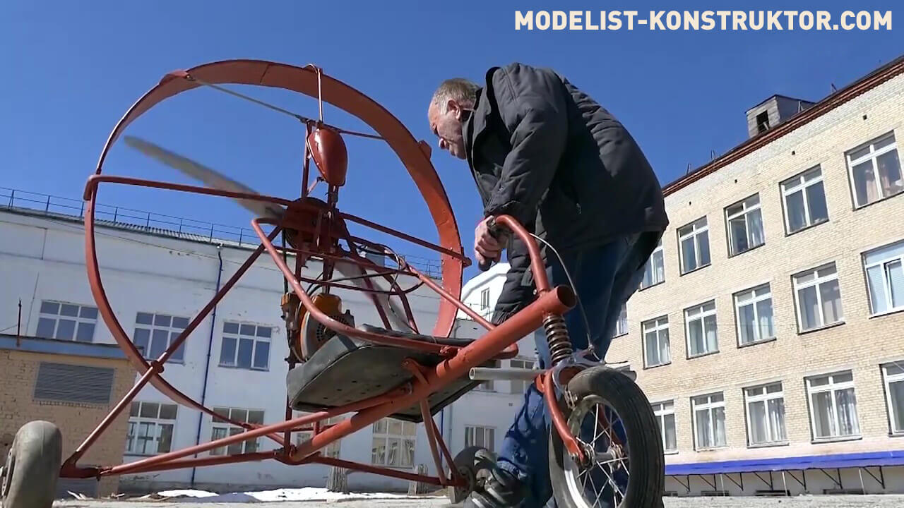
The idea of creating this vehicle originated with me a long time ago, after watching a story in the “You Can Do It” program about skiers with backpack aeropropulsion. It was clear that the legs of the motorized athletes were very tense, and the heavy equipment on their shoulders rocked them as they moved. To simplify and facilitate this process, I first decided to attach a frame to the engine. But then I decided that a propeller with a diameter of about 0.8 meters, shaded by the pilot’s back, was somehow frivolous and ineffective. I wanted to get something similar to a helicopter propeller, only operating in a different plane. The result was a ground vehicle with the unique specificity of operating in a narrow speed range, namely from 0 to 40 km/h. I admit that this design will cause a lot of doubts and controversy, as will the presented somewhat non-standard approach to its implementation. But, as they say, only those who do nothing make no mistakes.
Design
So, I set myself the task: to create a universal vehicle capable of moving on snow, land and water. Buoyancy, of course, is provided by floats instead of wheels in summer or skis in winter. There is no doubt that the aerocycle, as I called my brainchild, should be collapsible. A mandatory requirement for the device is ease of storage and transportation, because most of the time it will lie disassembled somewhere in the corner of the garage. Also, the aerocycle must be able to travel briefly on public roads and not be subject to registration with regulatory authorities, so the engine will naturally have a volume of up to 50 cm3. At the same time, I wanted to get a compact car, not encumbered by any body, extremely simple and light. This led to the restriction that it should only be single-seater.
An important point is that when using a low-power engine, it is necessary to obtain good thrust due to a large-diameter propeller. The propeller should not be afraid of small stones lifted from the ground while moving, that is, it should be metal and have the highest efficiency. I saw such a screw narrow and thin, and it was clear that its effectiveness would only manifest itself in a narrow range of rotation speeds. Expanding this range would allow the use of a variable pitch propeller (VPS). Also, the advantages of such a propeller are the ability to create reverse thrust for braking, change engine speed and developed thrust depending on the angle of installation of the blades.
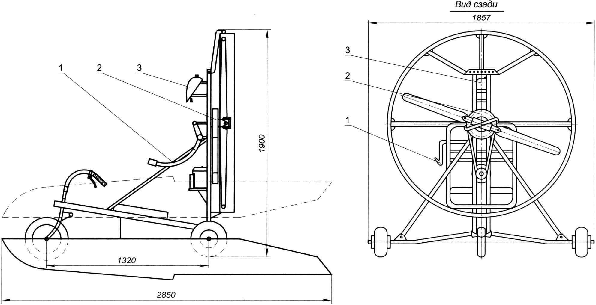
1 — rotor blade control handle; 2 — drive pulley and VIS system; 3 – fuel tank
Creating a lightweight single-seat aero-powered vehicle involves installing a propeller on the engine axis – this makes it 20-25% lighter. But at the same time, a pushing propeller with a diameter of 0.7-0.8 meters will be completely in the aerodynamic shadow, which will clearly reduce its effectiveness. I consider a propeller with a diameter of 1.4 meters optimal for such a vehicle, which, however, will entail an increase in weight by approximately 15 kg.
Based on layout considerations, it makes sense to use a V-belt drive to drive the propeller, ensuring a reduction in propeller speed relative to the engine by 2.7 times. And the double-groove propeller pulley makes it possible to later replace the motor with a more powerful one (up to 10-15 hp). Estimated propeller thrust is 30 kg.
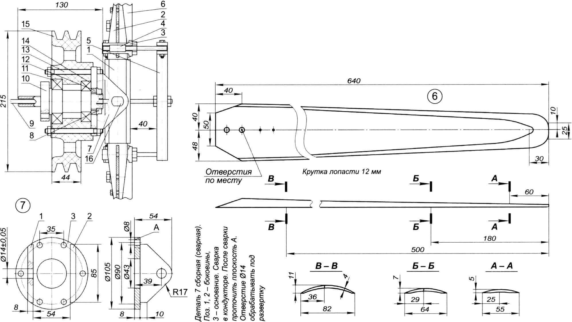
1 — screw bushing; 2 — screw-in butt of the blade (2 pcs); 3 — propeller blade control lever (2 pcs); 4 — propeller blade control rod (2 pcs); 5 — traverse for controlling the propeller blades; 6 — propeller blade; 7 — propeller hub; 8 — driven pulley nut; 9 — pitch control rod; 10 – axis; 11 — bearing No. 207; 12 — bushing; 13 — stud for fastening the screw hub (6 pcs); 14 — bearing No. 206; 15 — driven pulley; 16 — propeller hub drive pin
Theoretically, for normal operation of a vehicle, the required quality, defined as the ratio of the thrust of the aeropropulsion to the running weight of the structure, is in the range of 0.3-0.4. Unfortunately, in practice these results turn out to be lower – somewhere in the range of 0.2-0.3. Therefore, perhaps the water version of the aerocycle will be the most advantageous.
Engine
The basis is a light and compact, centrifugal clutch, two-stroke engine from a Ural chainsaw with a power of about 5 hp. Its design has long been outdated, and I would be very happy to use a four-kilowatt electric motor with a corresponding battery. It’s a pity, but this pleasure is still expensive, we will use what we have at hand.
The engine is attached to the drive pulley assembly with a clamp consisting of two halves, secured with M6 bolts. The clamp is made from a tube with a diameter of 12 mm. On one side, the metal is completely removed using a sharpening machine, then cuts to half the thickness are made with a hacksaw blade at regular intervals. The resulting workpiece was bent to the required radius, and the cuts were then welded.
Drive Pulley Assembly
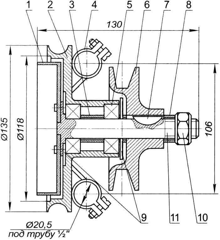
1 – drive drum; 2 – body; 3 – spacer sleeve; 4 — clamp for fastening to the sub-engine frame (2 pcs); 5 — bearing No. 203 (2 pcs); 6 – drive pulley; 7 – key; 8 — spacer sleeve; 9 — boot (2 pcs); 10 – nut; 11 – drive shaft
It consists of a shaft resting on two bearings No. 203. On one side of the shaft there is an automatic clutch drum, and on the other side a drive pulley is installed. The drive pulley assembly has four lugs for mounting on the subframe. It, together with the engine, can move through half-inch pipes, providing the necessary tension on the drive belt. Initially, a pulley with an outer diameter of 88 mm was used, but the engine was underloaded, so a pulley with a diameter of 100 mm was installed.
Propeller blades
For land transport, a wooden propeller is extremely undesirable due to rapid wear. Small stones rising from the ground while the engine is running quickly destroy it, so a metal screw is the only option for creating a workable structure.
The blades were made of a sheet of duralumin alloy 4 mm thick. I cut them out according to the template, and also made bends according to the template. I ground the edges down to zero with a file. After a slight twist, the blades were ground and polished.
Each blade is inserted into the groove of the blade butt screwed into the screw sleeve. The blade is clamped in the groove with four bolts M10, M8, MB and M5. A blade control arm is attached to the bottom bolt, connected to the blade control crossbar by an adjustable rod.
Screw sleeve
An important feature of this design is the use of a variable pitch propeller. The basic concept is taken from the design of the tail rotor of Vasily Artemchuk’s helicopter (see “M-K” No. 11-1997). Namely, the butts of the blades are screwed onto the M30x2 thread into the propeller hub. The 14 mm hole for the pin, which secures the screw to the hub, is machined using a reamer. When the propeller is operating, the hub can swing at a small angle to eliminate torques that arise due to errors in the manufacture or installation of the blades.
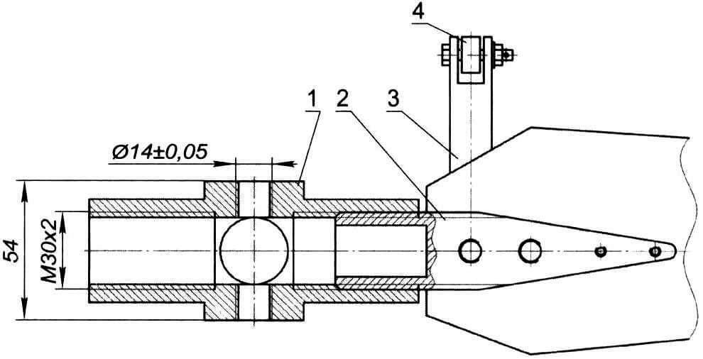
1 — screw bushing; 2 — screw-in butt of the blade; 3 — propeller blade control lever; 4 – thrust
The screw hub connecting the driven pulley to the screw hub is welded. Welding was carried out in a conductor with high current, followed by processing on a lathe.
Driven Pulley Assembly
It consists of an axle attached with an M16 nut and six bolts to the sub-frame. On the axis, on bearings No. 207 and No. 206, a pulley with a diameter of 220 mm, made of textolite, rotates. It is secured to the axle with a nut and a locknut. The axis has a through hole in the center with a diameter of 10 mm, through which the screw pitch control rod passes. The rod also passes through the screw mounting pin on the hub and is secured with nuts in the blade pitch control yoke. At the other end of the rod there is a bearing in a cage, through which the force of the pitch control lever is transmitted to the yoke, which turns the blades through rods. The hub is attached to the pulley with six through M8 studs.
Sub-frame
It consists of two half-inch pipes connected by a 3 mm thick plate welded to them and serving as a bracket for the screw axis. Also attached to this plate are the middle transverse tube of the propeller guard and the upper tips of the rear wheel chassis struts. The upper bracket of the screw guard is fixed from above to the ends of the frame with M8 bolts. Brackets for installing a fuel tank from a motorbike are welded to the frame tubes. The engine is mounted on four clamps at the bottom of the frame. The required belt tension is achieved by moving the drive pulley assembly down the subframe tubes. In the lower part, the sub-engine frame is fixed to the main tube of the aerocycle with a tie rod with adjusting washers.
Main frame tube
This is the “backbone” of the structure. It is made of a thin-walled pipe with a diameter of 52 mm and a wall thickness of 2 mm. For ease of storage and transportation in the trunk of a car, a flange connector is made in the middle of the pipe with four M6 bolts. In the front part, a guide tube for a fork from a children’s bicycle is welded, and at some distance a plate is welded for fastening the spacer frame and the seat, for which a cushion from a UAZ car is used. At the rear, the main tube is connected to the subframe using a tie rod and spacer bushings.
The spacer frame connects the main frame tube and the sub-frame. There is a pilot’s seat inside it, and it also serves as a backrest.
Chassis
The tail wheels from the An-2 are installed at the rear of the aerocycle. Instead of bushings, closed rolling bearings are used. The necessary grooves were made in them on a lathe. The wheel axle is fixed in a 3/4″ pipe, which also serves as a rear suspension arm. The front fork and wheel are taken from a bicycle with minimal modifications. A tube is attached to the front fork with M6 bolts and serves as a leg support. A bicycle brake is installed on the front wheel.
Propeller guard
To minimize the danger from a rotating propeller, this is to make a continuous guard for the propeller. Unfortunately, it increases the weight of the structure by about 10 kg and worsens performance characteristics. A compromise option is a fence in the form of an aerodynamic ring. At the same time, it will even increase the efficiency of the propeller by straightening the air flow and reducing the flow of air from the high pressure area behind the propeller to the low pressure area in front of the propeller – the so-called “air flow circulation” will be obtained. All this allows you to increase traction by 10-20% without additional power consumption.
The fence is made of steel sheet 1 mm thick and steel tube with a diameter of 12 mm. For ease of transportation and storage, the ring is disassembled into 4 parts. Perhaps, based on the weight characteristics, not the best option was chosen, but it is more reliable from the point of view of ensuring the safety of the pilot and others.
Floats
There is nothing complicated here: the technology for making floats has been repeatedly described in the magazine in relation to small catamarans.
A special bracket is installed in the area of the steering wheel to secure the float. The rear part of the float is attached to the rear suspension arm.
Propeller pitch control system
Under the pilot’s left hand there is a lever of a complex shape of the VIS system. It also has a carburetor throttle control lever installed on it. The lever has two supports welded to the screw axis mounting plate. Between them there are plates with a groove for moving the control bearing axle box when moving the pitch control rod. There is a rolling bearing with an internal seat diameter of 8 mm on the rod; it is fixed on the rod with two M8 nuts, which ensures adjustment.
The pitch control system works great in all propeller modes. There was a fear that the centrifugal force acting on the blade would wedge (clamp) the threaded butt of the blade, but this was not at all justified: the handle moves easily in all positions of the blades.
Results
Let me summarize. When testing the device, it turned out that the screw was too light, so the diameter of the drive pulley had to be increased from 88 mm to 100 mm. In addition, the pulley profile turned out to be somewhat small, which was eliminated during replacement. Power transmission of 5 hp required a serious attitude towards the drive belt. To ensure reliable operation of the transmission, it is necessary to mount the engine very rigidly and, preferably, provide an additional tensioning device.
The propeller proved to be excellent – it is easy to control at all speed modes, there are no vibrations. But it turned out to be quite narrow-range. A screw made of a thin profile is easier to rotate, but flow stall occurs much faster. In this case, there is an effect of increasing thrust when accelerating, that is, the propeller leaves the “aerodynamic bag”.
Now about the sad thing. Despite the fact that the aerocycle was able to “fit” into the trunk of the GAZ-3102, various changes from the design sketch resulted in its significant weight. The total weight of the device is now about 60 kg, which significantly offset the 20-30 percent increase in thrust of a large-diameter propeller. In this type of construction, it is, of course, better to replace heavy steel with aluminum or composite materials.
However, I believe that time and resources were well spent. This work for me was more of an experimental value than a practical one, allowing me to better understand the specifics of the design, manufacture and operation of a vehicle with an aeropropulsion engine.
Pavel KOPYEV, Beloretsk
Recommend to read
 GREGORATOS – UNIVERSAL
Perfectly round rubber gasket of any size or belt for the tape drive of the tape, you can cut from a sheet of rubber with this simple device. In addition, it can be used for cutting of... Mini-Moped Made from a Bicycle
The age of the members of the "Planeta" young technicians station varies greatly: from elementary school students to graduates. And if high school students are more interested in serious...
