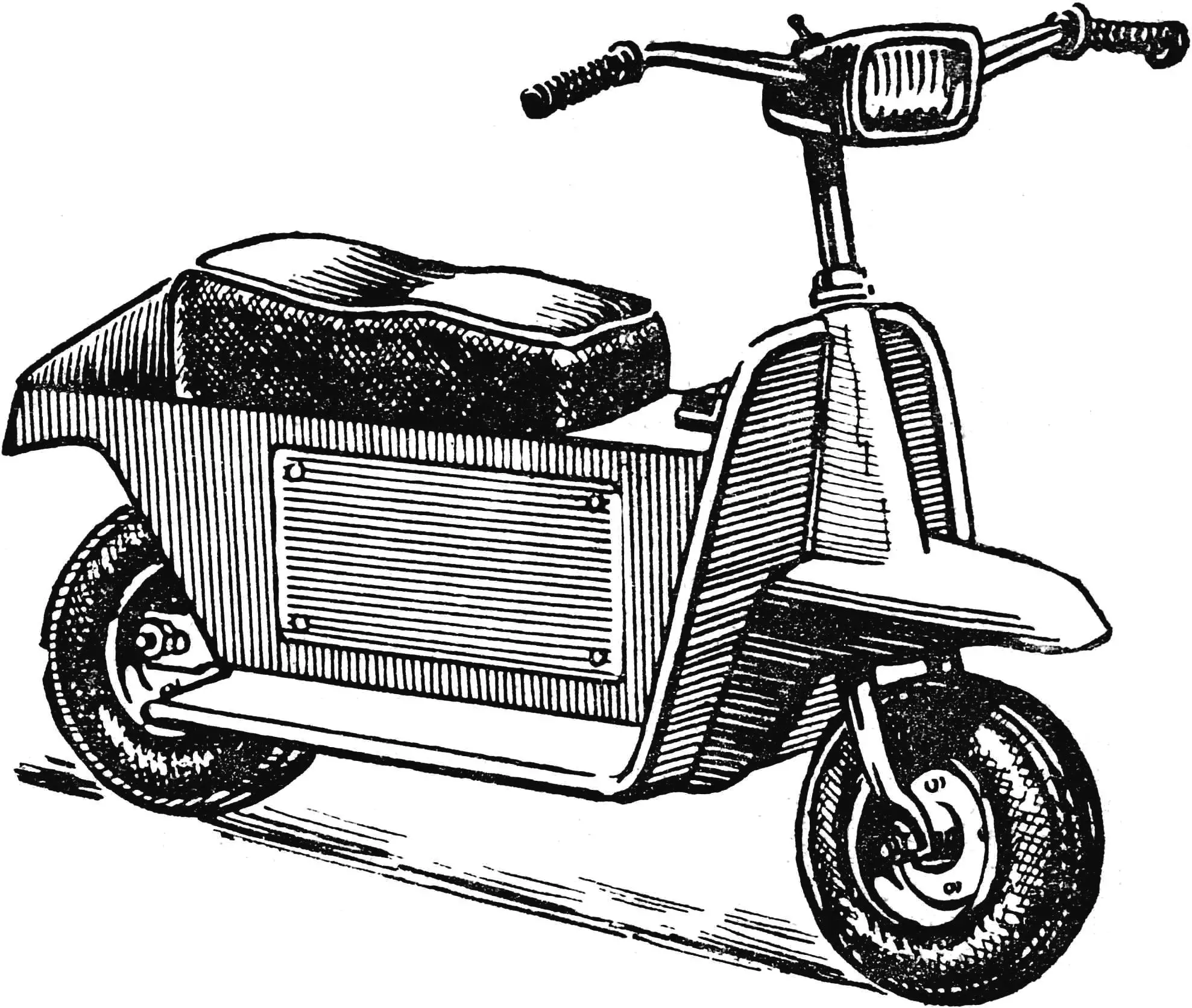
«After the publication in issue 12 of 1971 of the magazine «Modelist-Konstruktor» of the article «Meet the Tulpar» we received many letters from readers asking to send drawings and descriptions of various components of the Tulpar electromotor scooter. Since we cannot send drawings to each reader individually, we ask you to print them in the magazine».
Laboratory of Micro-Displacement Engineering, Alma-Ata Regional Young Technicians Station
The Tulpar motor scooter was built on the basis of a children’s scooter made in the GDR. Figure 1 shows how the rear part of the scooter frame was modified. Frame 4 was cut, two tubes 5 with wheel hubs and angle-iron platforms for mounting the motor with reducer 6 with four screws 13 were welded to it.
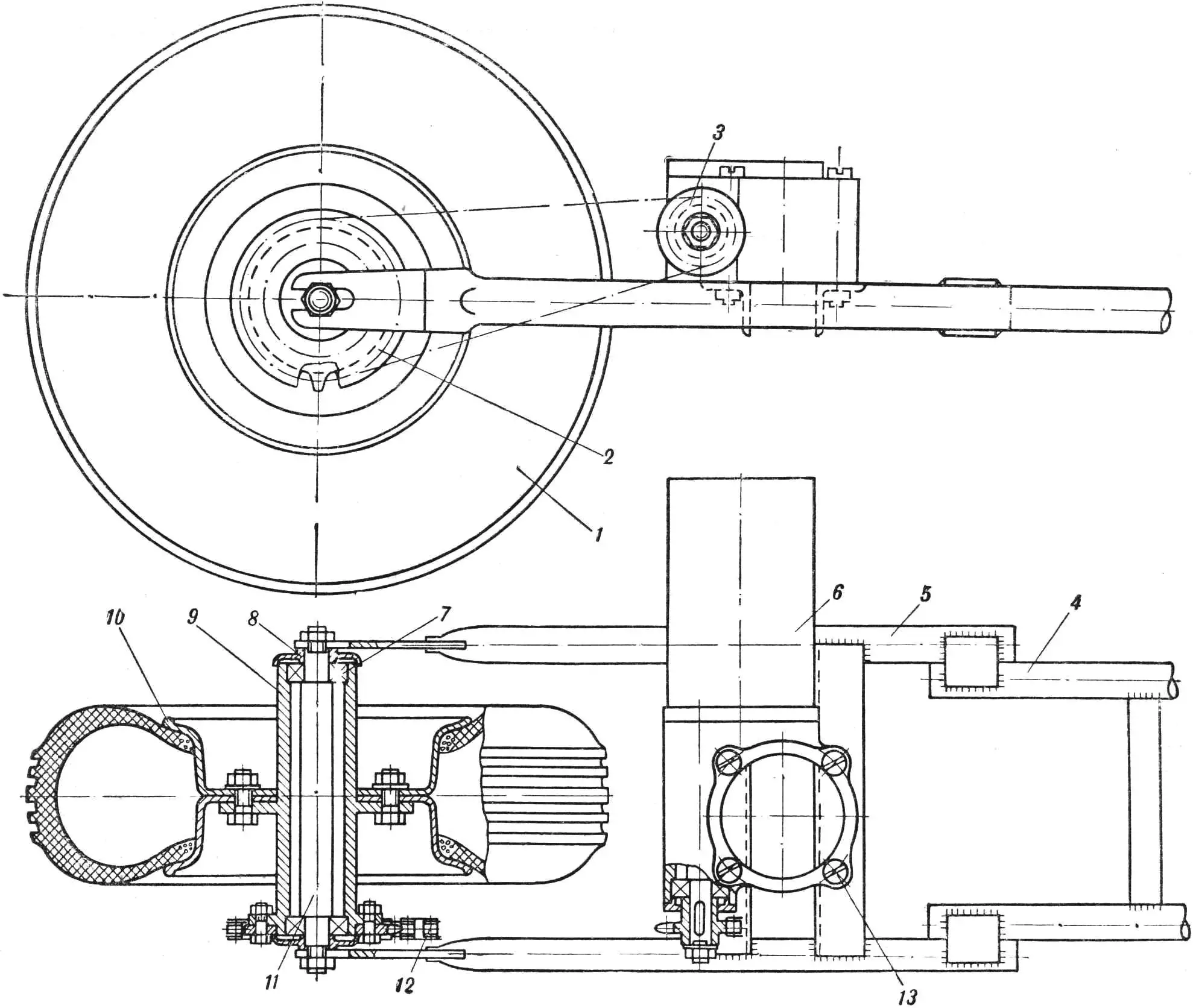
1 — kart wheel, 2 — driven gear, 3 — drive gear, 4 — main frame, 5 — welded tube, 6 — reducer, 7 — bearing, 8 — cap, 9 — rear wheel hub, 10 — disc, 11 — axle, 12 — chain, 13 — screw.
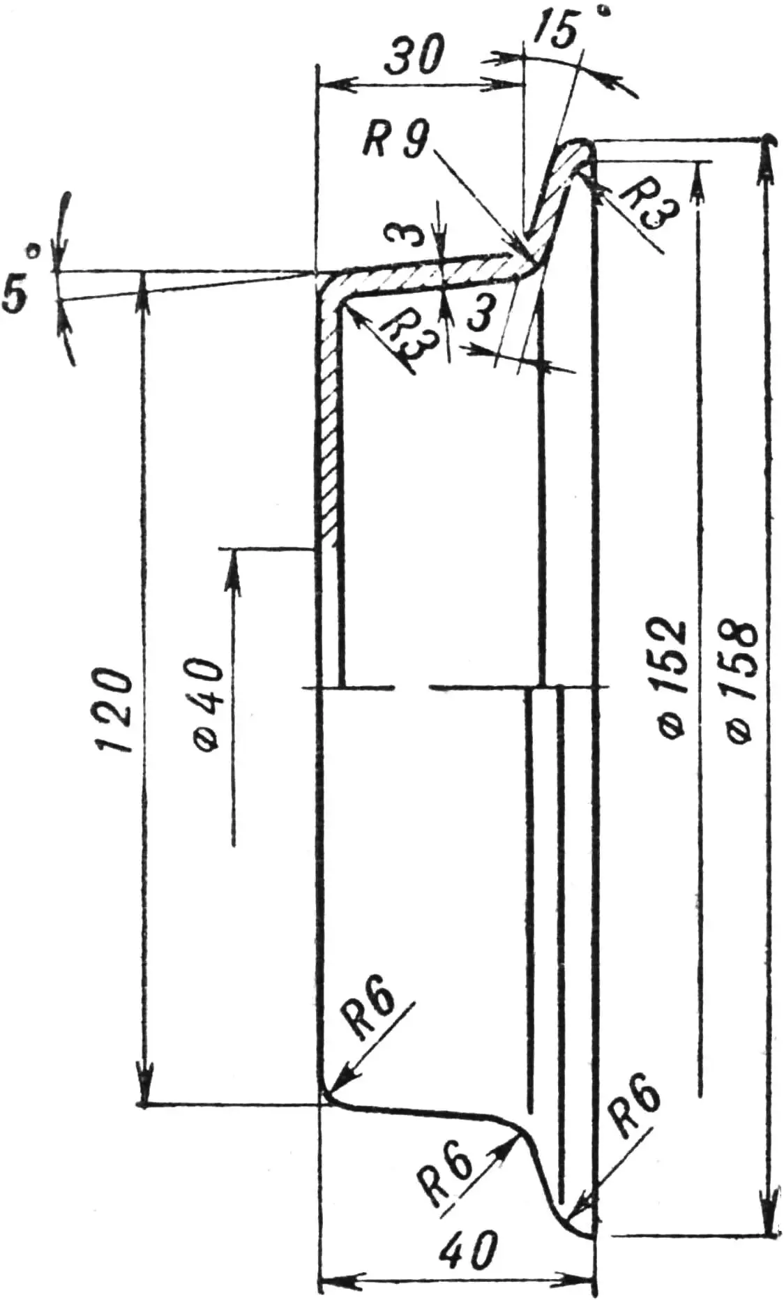
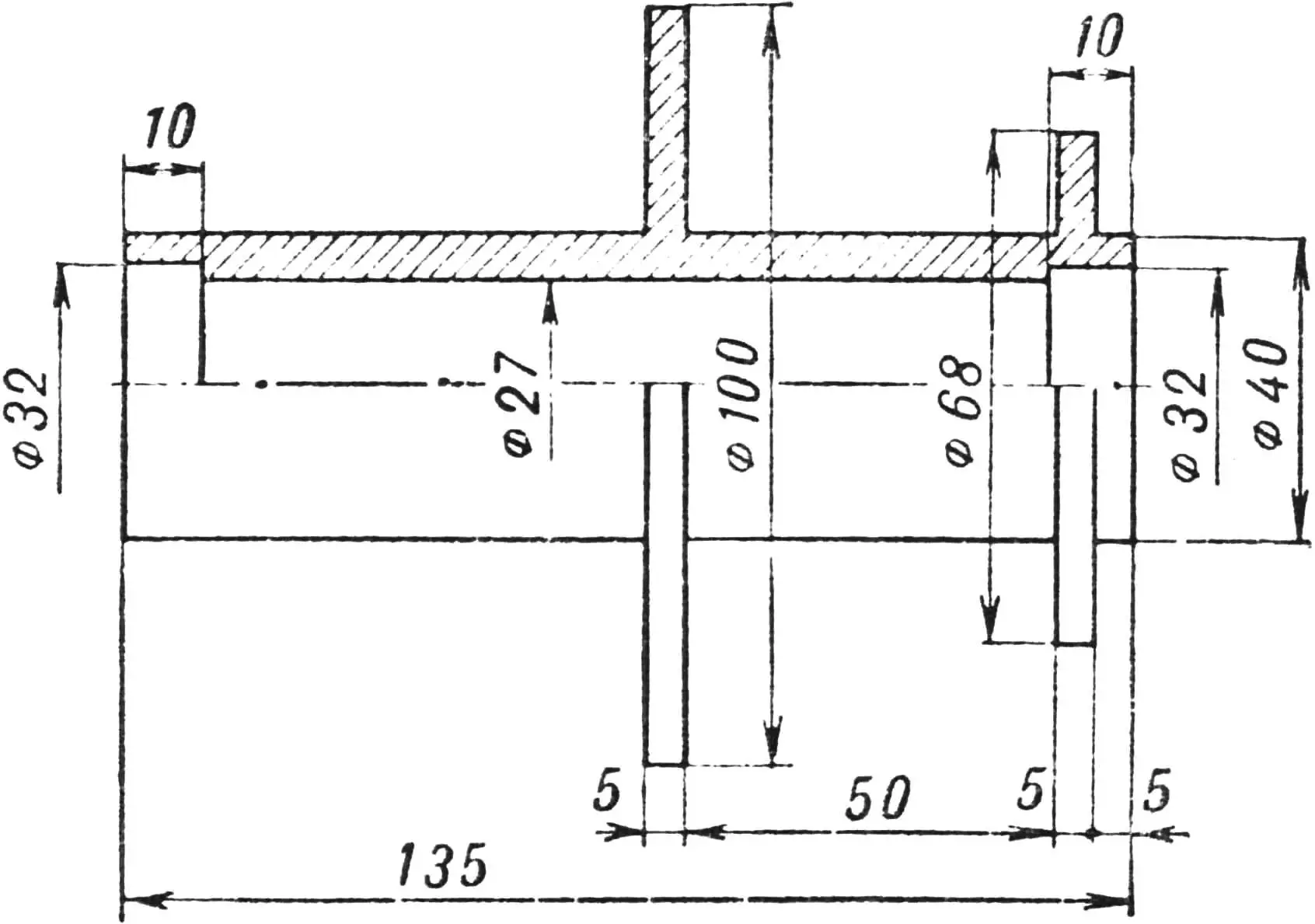
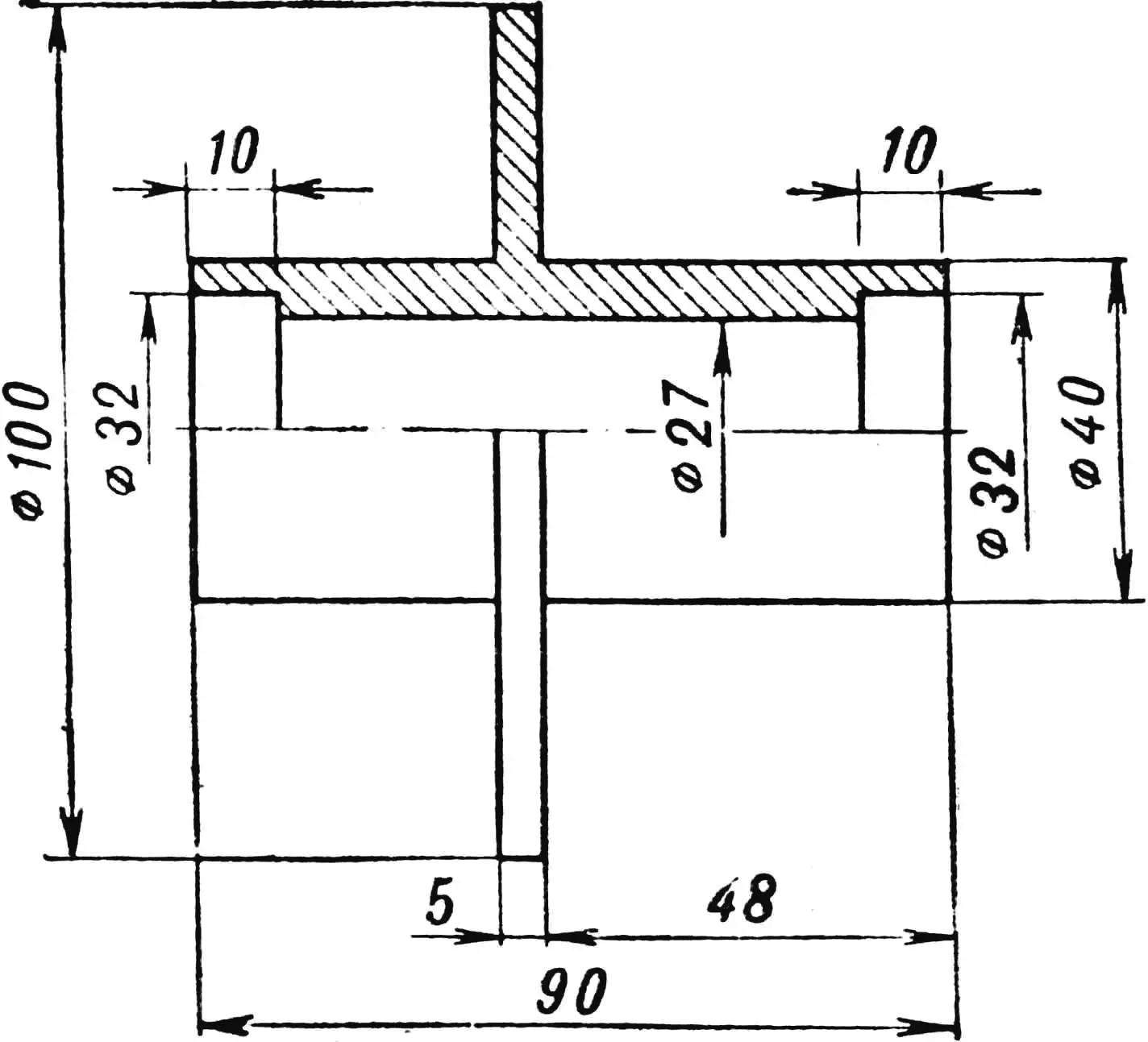
The front part of the frame was left unchanged, except for the handlebar and fork. The latter was widened due to the use of wider wheels. Tyres 1 are from a kart, model V-29, 3.5 × 5, 300 mm diameter. Wheel discs were turned from aluminum. Figure 2 gives their main dimensions. Figures 3 and 4 show the dimensions of the front and rear hubs. The front wheel axle is the same in design as the rear but somewhat shorter. Wheels are mounted on ball bearings No. 202. Wheel bearings are enclosed on the outside by dust caps 8 from K-55 motorcycle wheels.
Body panels, front fender and shield are made from 1 mm thick duralumin sheet, then covered with fiberglass cloth in epoxy resin.
The drive is the UR-6 electromechanical unit used in aircraft electrical equipment. UR-6 is a reducer with gear and worm drives and MU-431 electric motor. UR-6 cannot be used as-is because of the reducer’s high gear ratio. So the worm drive was removed from the reducer, a steel-turned shaft was put in place of the worm, the gear taken from the worm was fitted on one end, and gear 3 of the chain drive to the rear wheel is fitted on the other end. Thus the reducer keeps only the gear drive with ratio Z = 3. Gear 3 has 7 teeth, is homemade, fixed on the shaft with a nut and prevented from turning by key 13. Chain 12 of the rear drive is from a bicycle. The rear gear has 23 teeth and is fastened to the hub with four bolts.
The motor is powered by a 24-volt battery 12SAM-28, also used on aircraft. Capacity 28 A·h. In the battery the link between the 6th and 7th cells was cut and leads were taken from them to a switch. The switch connects both halves of the battery in parallel or series, giving 12 or 24 V and allowing speed control.
The charger is a standard rectifier with 24 V output and 3 A current, powered from 220 V mains.
«M-K» 7’73, V. YEGOROV, laboratory head, Alma-Ata
Recommend to read
 FROM “PIONEER” TO “JUNIOR”
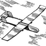
Throwing glider pioneer. Non-motorized model glider is very popular among modelers. Made in the form of models of monotypes, throwing gliders allow for fun competitions on the range,...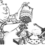 Flour from a… meat grinder
More and more often the editorial office receives letters and phone calls with the same request — to publish drawings and explain how to build a simple flour mill with your own hands. The...
