Tourist trips, water competitions, fishing! How many unforgettable summer days and winter dreams are associated with them! But for these dreams to come true, first of all, you need to have some kind of vessel. Here’s at least this catamaran with the tempting name “Rest”!
You, of course, know that a catamaran is a vessel consisting of two hulls connected by a platform or superstructure for passengers and cargo. There are motor, sail, and rowing catamarans. Depending on the mode of movement on water, catamarans are divided into displacement and planing. There are vessels consisting of three hulls connected by one common platform. They are called trimarans. In general, vessels with several hulls connected to each other are called polymarans (from the word “poly” — many).
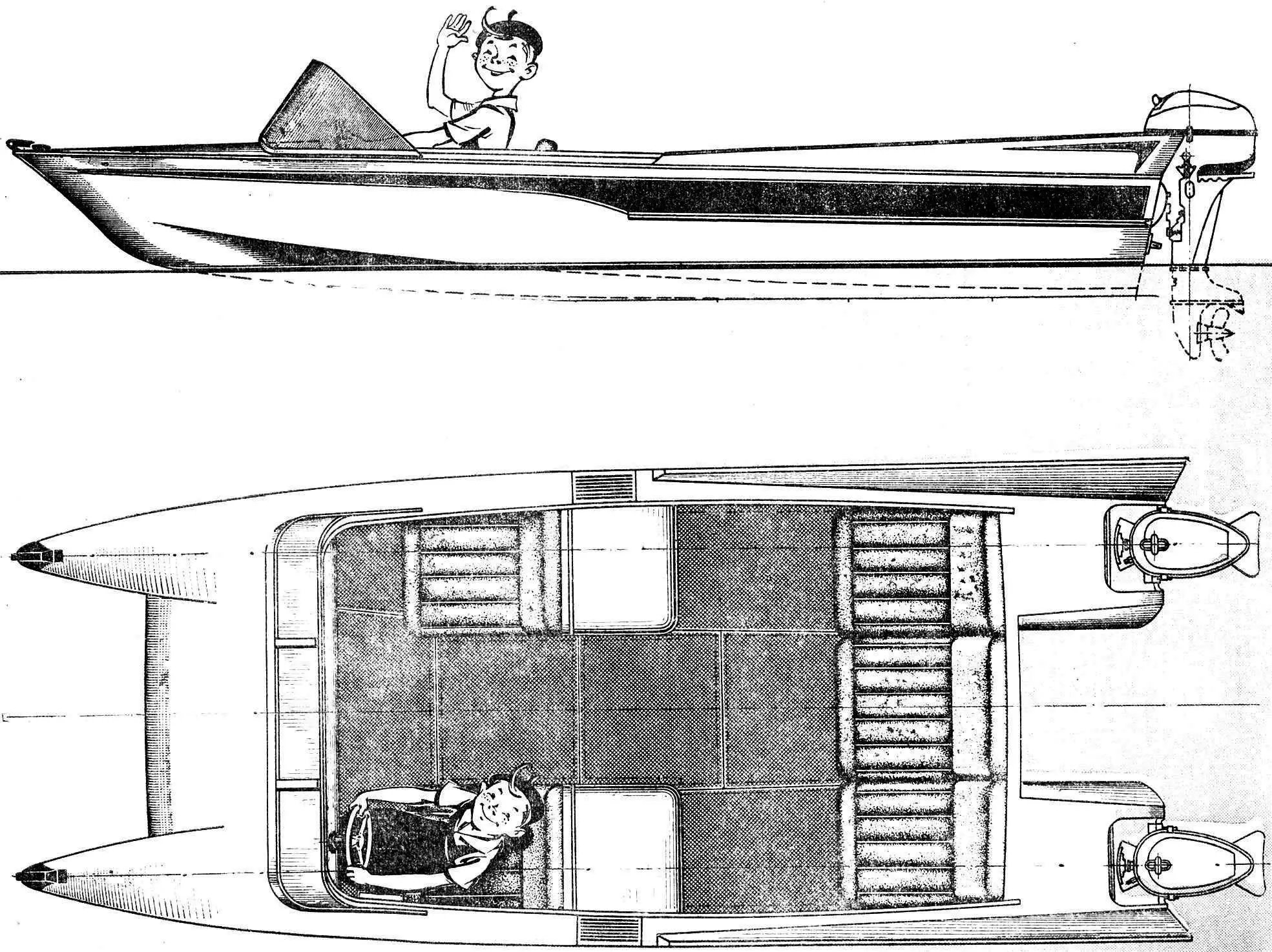
The catamaran “Rest” is motorized and planing. With relatively small dimensions, the hull has a fairly high freeboard, protecting the driver and passengers from water splashes and ensuring safe sailing in “fresh” weather. The strong hull makes it possible to operate the catamaran at high speeds, with “Moskva” outboard motors and more powerful motors.
The catamaran hull consists of two symmetrical floats connected by a bridge, forming with the sides of the floats one common platform 2.66 m long and 1.63 m wide, on which five seats are placed. The bottom of the floats is V-shaped, smoothly transitioning to the stern into an almost flat platform, ensuring planing on the water surface. The sides of the floats in the bow have a slight flare, serving to deflect splashes when moving on a choppy water surface. At the stern, the sides are slightly sloped. This is done so that the water exiting from under the bottom does not wash over the sides and does not slow down the catamaran’s movement. On the deck at the stern, low wings are made, protecting the stern section with motors from splashes. The lower surface of the platform is flat, smoothly descending to the stern, and the clearance height under the platform is chosen so that when the catamaran moves, the platform does not touch the water.
General arrangement. The catamaran hull is divided into three compartments.
The bow part of both floats is used as a forepeak, where various items necessary for sailing are stored. In the middle part of the hull, there is a cockpit designed for five people. Two front seats are spaced to the sides, at the stern wall — one three-seat sofa. The seats are made of foam rubber covered with colored textovinyl. Boxes intended for storing food and luggage adjoin the backs of the front seats. The bottom part of the cockpit is closed with slats made of waterproof plywood, in the front part a wide windshield made of plexiglass with a metal frame for attaching the awning is installed. On the windshield at the sides, running lights are attached (green on the starboard side, red on the port side) and signaling lights. In the middle part of the glass at the top, a masthead light is installed. The running lights and signaling lights receive power from a motorcycle-type battery installed in a special box in the stern part of the cockpit under the seat of the left float.
A tent made of polyethylene film, stretched over the windshield, and two U-shaped folding frames made of duralumin tubes can be installed on the catamaran. The frames are installed in sockets on the inner lining of the cockpit. On the port side in the front part of the cockpit, there is the driver’s station. The control panel has a steering column with an automobile-type steering wheel, connected to the outboard motors through a steering cable transmission, a “reverse — throttle” block handle, a speed indicator gauge, recalculated from pressure kg/cm2 to speed readings in km/h, and light switches. A socket for a signaling flag is also provided here. On the front panel, there is also a place for a clock and brackets for attaching a portable battery receiver of the “Atmosphere-2” type.
Two “Moskva” outboard motors are hung on the transoms of the floats, fuel tanks are installed under the deck. The motors are connected by remote control of reverse and throttle to the driver’s station using rigid rods and cables in a flexible metal sheath.
Stationary engines of small weight, for example from motorcycles “K-750”, “M-72”, “M-61” or from a “Zaporozhets” car, can also be installed on the catamaran “Rest”. But in this case, it is necessary to make a special foundation. For the propeller to work under normal conditions, the engine installed on the platform in front of the stern seats must be lowered together with the bottom of the platform, and the propeller shaft bracket must be installed under the so-called anti-cavitation plate. Any stationary engine must be equipped with remote control of reverse and throttle from the driver’s station.
For towing and mooring the catamaran, two shaped rings with carabiners are installed on the deck at the bow ends of the floats, preventing the towing lines from slipping. In the stern part on the transoms of the floats, there are aluminum handles serving for carrying the catamaran, mooring, as well as for securing it during transportation on a car or cart.
HULL CONSTRUCTION
The catamaran hull is mainly made of pine. The keel with a cross-section of 25 X 50 mm is joined to the stem “on a scarf” without additional fasteners. The stem is glued from 4 pine and 2 oak planks with a cross-section of 8 X 80 mm on a special template. The chine stringers and gunwales are of the same cross-section (20 X 30 mm), the bottom stringers are 18 X 30 mm, the side ones are 15 X 30 mm. The underdeck (12 X 15 mm) and longitudinal (15 X 30 mm) connections of the platform are also made of pine.
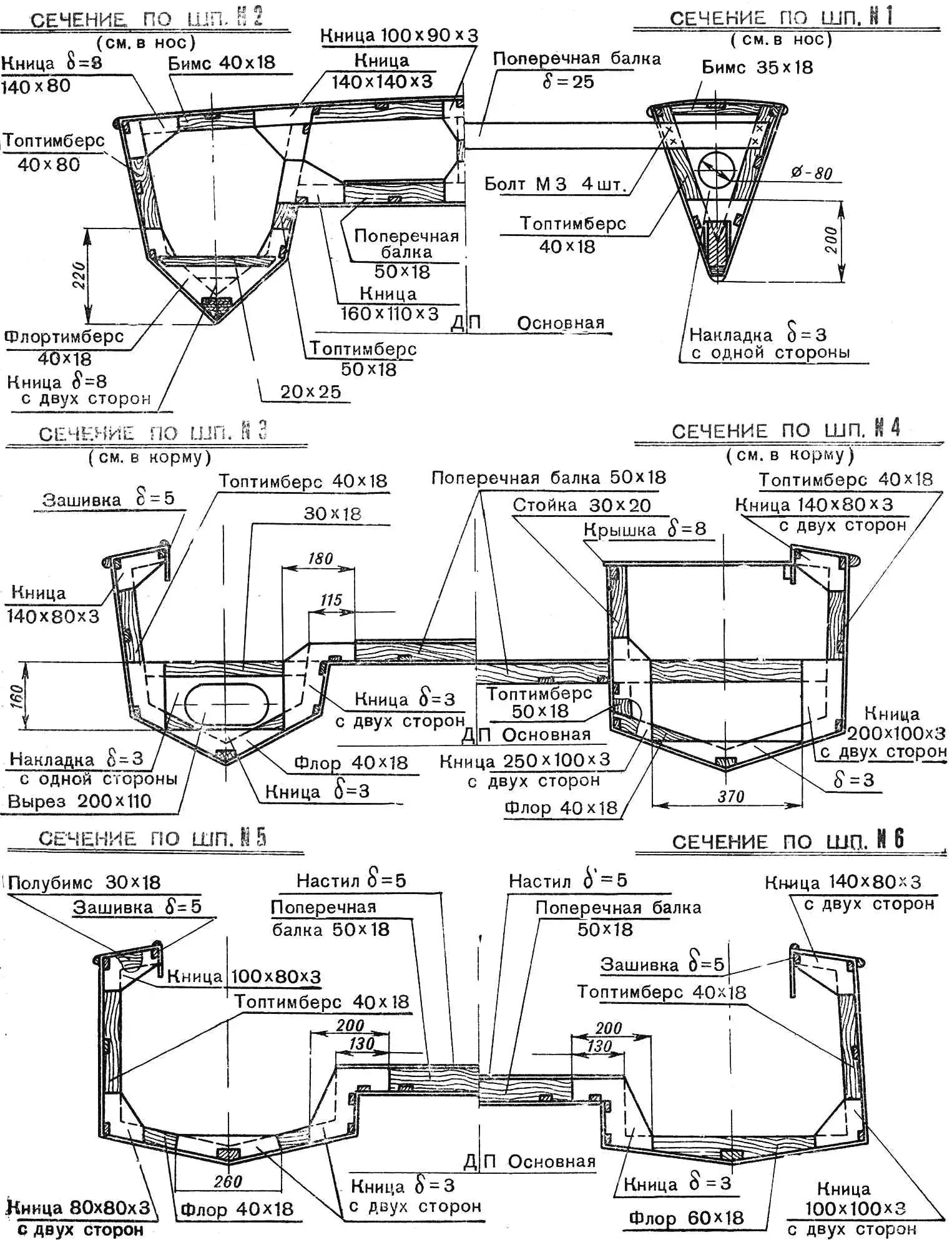
The frames are assembled from pine blanks with a cross-section of 40 X 18 and 50 X 18 mm, with the frame frames of the floats assembled from blanks with a cross-section of 40 X 18 mm, and the inner top timber of the float and the transverse beam of the bridge — from bars with a cross-section of 50 X 18 mm. All frame elements are connected to each other in a butt joint and fastened with plywood knees 3 mm thick on “VIAM-B3” glue, with pressing with nails 1.5 X 20 mm. The frames of the front and rear seats are made of pine blanks with plywood knees and are assembled during equipment installation on “viam-b3” glue.
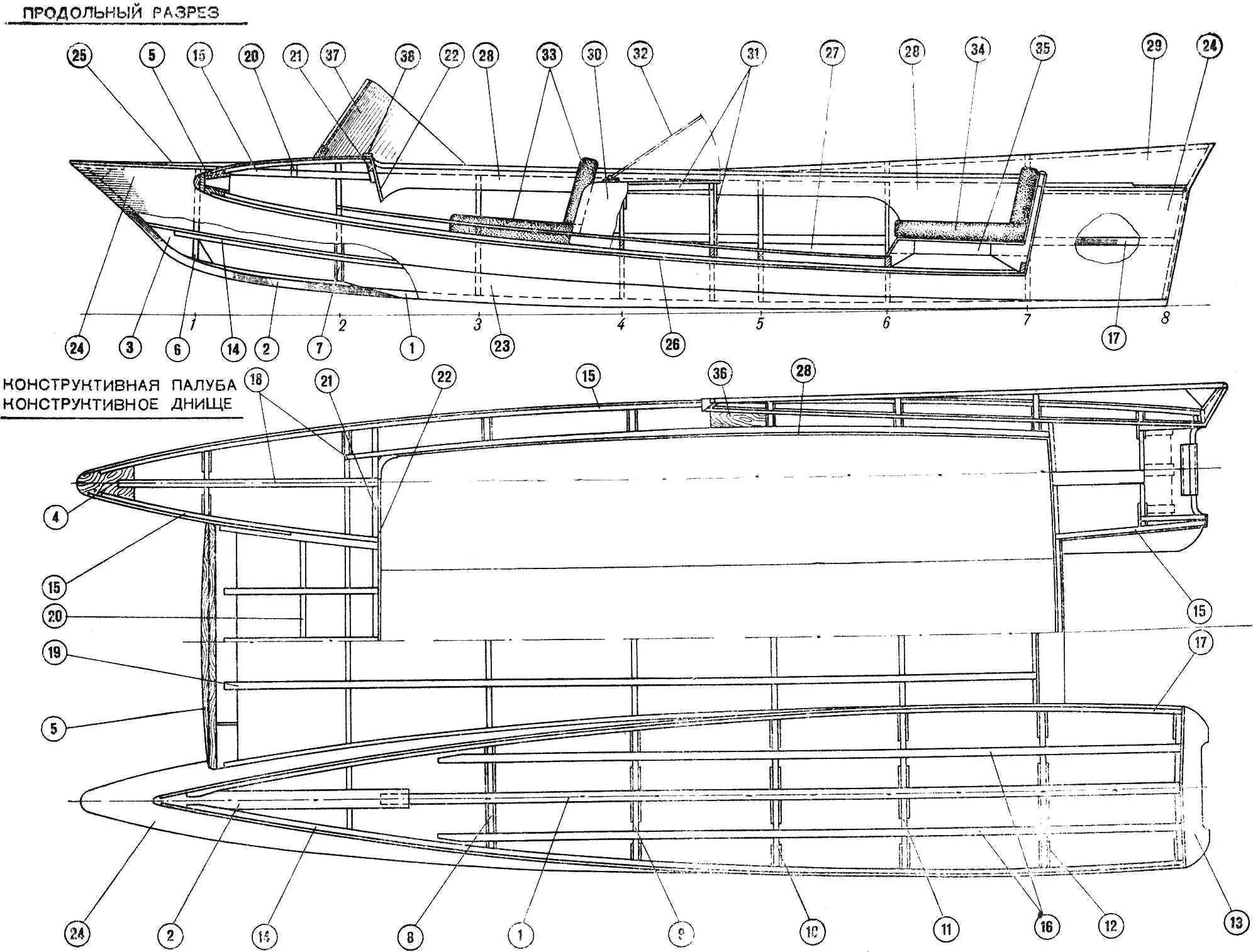
1 — Keel; 2 — Stem; 3 — Bow button; 4 — Bow breasthook; 5 — Block; 6 — Frame No. 1; 7 — Frame No. 2; 8 — Frame No. 3; 9 — Frame No. 4; 10 — Frame No. 5; 11 — Frame No. 6; 12 — Frame No. 7; 13 — Frame No. 8 (transom); 14 — Chine stringer; 15 — Top stringer; 16 — Bottom stringer; 17 — Side stringer; 18 — Deck stringer; 19 — Bridge stringer; 20 — Half-beam; 21 — Half-beam; 22 — Panel; 23 — Bottom planking; 24 — Side planking; 25 — Deck planking; 26 — Bridge planking; 27 — Bridge decking; 28 — Cockpit coaming; 29 — Bulwark planking; 30 — Luggage box planking; 31 — Luggage box frame; 32 — Box lid; 33 — Bow seat; 34 — Stern seat; 35 — Seat frame; 36 — Filler; 37 — Windshield; 38 — Front cockpit coaming.
Then plywood seat panels with foam rubber covered with textovinyl are installed on the frame. Behind the front seats, luggage boxes are mounted, the frame of which is assembled from pine blanks with a cross-section of 20 X 30 mm and sheathed with 3 mm thick plywood. A plywood lid 6—8 mm thick is installed on top on a hinge, serving simultaneously as a table. Inside the cockpit along the deck, a coaming made of 3 mm thick plywood is installed on screws 3 X 15 mm, which on the deck side is closed around the perimeter with ash trim. The front panel is made of 8 mm thick plywood and attached with glue and screws to the beam using wooden blocks.
BS grade plywood is used for hull planking. The bottom of the floats and the platform decking are made of 5 mm thick plywood. The sides, deck, and platform planking are sheathed with 4 mm thick plywood, the bulwark has a planking thickness of 3 mm. Above the planking along the groove of the side with the deck, an ash rubbing strake with a cross-section of 25 X 30 mm is installed. The catamaran frame and planking are covered twice with hot linseed oil from the inside and primed with red lead or primer No. 138A. The seat backs, box planking, front panel, cockpit coamings, trim, and rubbing strakes are covered with “walnut” stain and then varnished three times with “6s” oil varnish. Outside, the hull at the joints is covered with strips of fiberglass on epoxy glue for better waterproofing and painted with pentaphthalic paints.
It should be noted that the hull construction is designed for two “Moskva” motors. The use of more powerful outboard or stationary motors (up to 2 X 20 hp) is possible, but in this case, it is necessary to increase the thickness of the bottom planking of the floats to 6 mm and introduce additional transom fasteners. No other changes need to be made.
CATAMARAN CONSTRUCTION
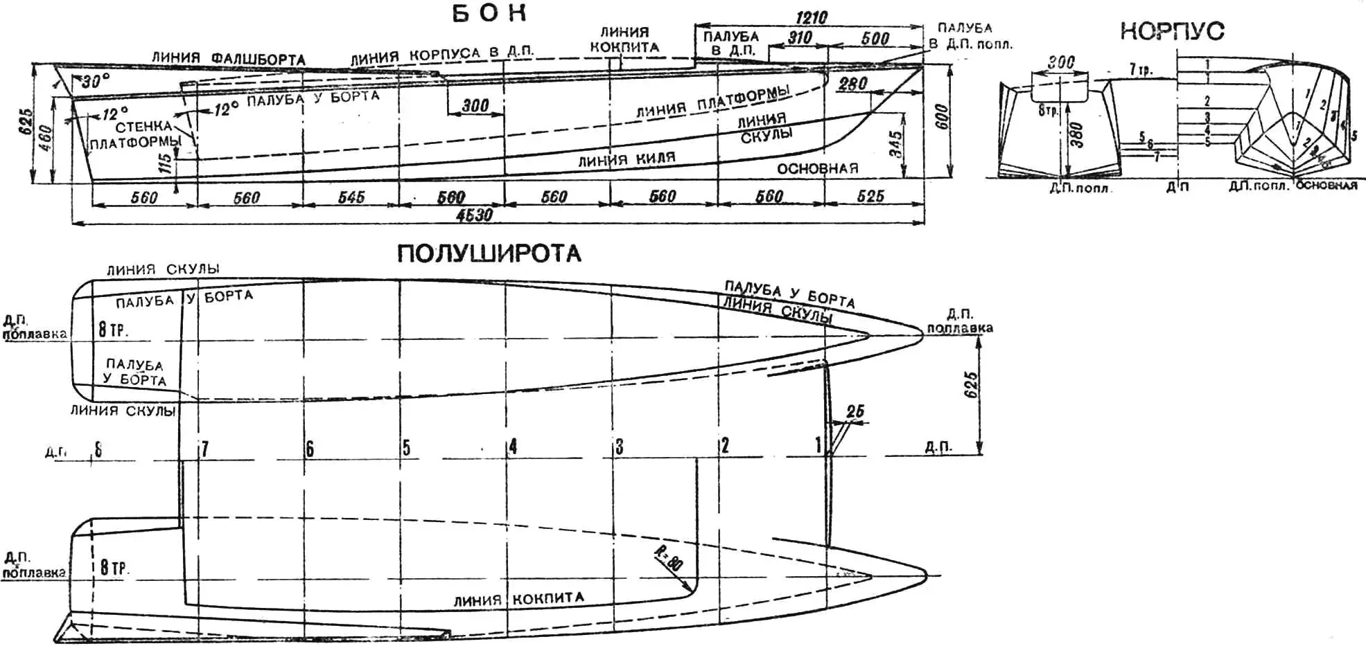
We start with laying out the loft. On a plywood board 2 m wide and 0.8 m high, we draw a vertical line — the axis of symmetry of the hull — and mark it with the letters DP (diametral plane). At a distance of 625 mm on each side parallel to DP, we draw the axes of symmetry of the floats (DP of floats), laying out a grid around them with a cell size of 100 X 100 mm and ensuring strict perpendicularity of line intersections. On these grids, according to the table of loft ordinates and the theoretical drawing, we draw the frames in full size, applying the width of the frame elements and drawing all the knees according to the construction drawing. From the loft, we take the shape of the knees in full size, transfer them to plywood and cut them out. Applying the blanks to the loft, we mark and cut all the elements to size: beams, top timbers, floor timbers, related to one frame. Then we arrange on the loft around the perimeter of each frame all the elements and, placing the knees in the right places, fasten these elements into one whole with several nails. Then, turning the frame over, we install the knees on the other side. We assemble all other frames in the same way. After assembly, the frames are glued with “VIAM-B3” glue, ensuring that their contours match the drawing on the loft.
We nail the knees to them with glue using nails 1.5 X 20 mm. After this, the frames must be dried for 24 hours at a temperature of 20°C or higher. At lower temperatures, the holding time increases.
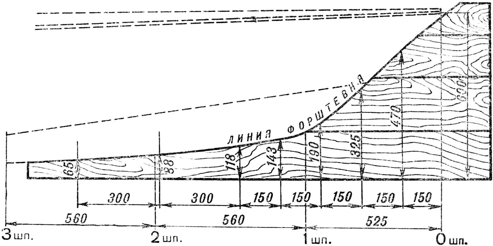
The stems are glued on a special template, the design of which is shown in the figure. The prepared strips are smeared with glue and sequentially laid one on top of the other in a “package”. Then the “package” is placed on edge and pulled to the template with clamps. In this case, the oak strips when bending the “package” should be on the template side. The “package” must be pressed until it completely repeats the shape of the template. After this, the “package” should be dried. When the blank dries, it is removed from the template, the glue drips are chipped off, and with the help of a plane, an even surface and width corresponding to the dimensions on the drawings are achieved. The width of the strips in this regard should be taken slightly larger than the width of the stem.
Having prepared the parts for the stem and keel, you can proceed to their connection, fitting the “scarf” so that there is no break at the joint and one continuous smooth line is obtained. After fitting the “scarf”, the keel with the stem is glued and compressed with clamps. The “scarf” on the parts to be joined must be planed to a length equal to ten times their thickness. Such a connection does not need additional fastening and holds reliably with glue alone. To the keels (two keels with stems), the front blocks are attached with glue. After this, you can proceed to the manufacture of the building jig.
| Frame No. | Height from baseline | Half-breadth | ||||||||
|---|---|---|---|---|---|---|---|---|---|---|
| keel line | chine line | platform line | deck at side | deck at DP | cockpit line | chine line | platform line | deck at side | cockpit line | |
| 1 | 164 | 315 | 495 | 587 | 612 | – | 63 | 120 | 155 | – |
| 2 | 85 | 233 | 363 | 569 | 612 | – | 162 | 196 | 234 | – |
| 3 | 50 | 165 | 288 | 552 | – | 575 | 230 | 250 | 278 | 128 |
| 4 | 29 | 117 | 233 | 536 | – | 560 | 280 | 290 | 304 | 154 |
| 5 | 12 | 82 | 187 | 518 | – | 545 | 311 | 305 | 310 | 160 |
| 6 | 0 | 57 | 152 | 500 | – | 530 | 326 | 315 | 300 | 150 |
| 7 | 0 | 32 | 115 | 483 | 525 | 515 | 326 | 315 | 275 | 125 |
| 8 tr. | 0 | 20 | – | 460 | – | – | 326 | – | 228 | – |
The building jig is made from two boards 40—50 mm thick with ribs along the keel bend line. These jig beams are installed strictly parallel, at a given distance from each other, and securely fastened into a single whole. Then the keels are installed on the jig beams, which are temporarily secured in the required position, and the frames are marked according to the theoretical drawing. The attachment points of the chine stringers are also marked on the stems. Cuts for the keel are made in the frames to the required depth. Frames 1, 2, and 3 are placed forward from the marking line, and 4, 5, 6, 7, and 8 — aft. When fairing the hull, excess wood on the frames can be removed with an appropriate bevel. The frames are fastened to the keel with glue using screws 4 X 40 mm (two pieces per frame), screwing the screws from the keel side. After installing the frames, the bow block of the bridge should be secured. All frames are temporarily connected to each other with longitudinal strips and proceed to install the gunwales, fastening them with glue and screws 3 X 30 mm in the frame cuts, specially made to the size of the gunwales. Then, in the same way, the chine and bottom stringers, longitudinal connections of the bridge, underdeck connections, and side stringers are installed.
Having checked the reliability of the fastening of the longitudinal elements of the hull, you can begin fairing. The hull is faired using a plane, periodically applying a flexible strip to the planed place and achieving a smooth bend of the contours without gaps and protrusions. The control strip should be of such length that it lies simultaneously on at least three frames.
After fairing the hull, they proceed to its planking. First of all, the sides are sheathed with plywood panels. For each side, pre-cut plywood is cut out, fitting the joints so that they are located on the frames. The joining of planking sheets is done by gluing them “on a scarf” with a length of at least 50—55 mm. The “scarf” on the planking is positioned so that it is directed against the catamaran’s movement. After cutting the planking panels, the joints are planed “on a scarf” and smeared with “VIAM-B3” glue. Carefully laying one on top of the other, the panels are folded into a package, fitting the joints. Then, at the joint locations, even bars are placed on top and bottom and tightened with clamps from both sides, achieving the necessary pressing of the glued plywood. The dried package of planking panels is separated, cleaned of excess glue, and installed on the sides, achieving the position corresponding to the cut. After this, from the inside, the outlines of the frame are traced on the planking with a pencil, it is removed, and holes for screws are drilled at equal distances in the places where it adjoins the frame. Having smeared the side with glue, the planking is put in place, evenly tightening with screws 3 X 15 mm from the middle to the bow and stern.
At first, the screws are placed sparsely, achieving only the planking’s adherence to the entire glued surface, and then intermediate screws are added. This is done so that the thin film of glue applied to the wood begins to harden after the planking is mainly pulled to the frame. The bottom planking is prepared and installed in place in the same way. After sheathing the sides, the hull acquires sufficient rigidity, so it can be removed from the building jig and turned over.
The bulwark and deck planking is done with glue and pressing with small nails. This is quite sufficient for their reliable fastening. Moreover, the joints of planking sheets on the deck can be joined on the beams edge to edge. After the hull planking is finished, excess plywood is removed, glue drips are cleaned, and they proceed to gluing the planking joints with fiberglass strips and priming the hull. The hull is treated outside and inside with primer No. 138A with preliminary coating with hot linseed oil. Then the seat frames, luggage boxes, cockpit coamings are made and installed in place, the front panel is varnished and mounted, the slats are fitted in place and primed. The steering and remote control of the motors and electrical wiring are mounted last.
It is good to paint the hull with paints of contrasting colors, but no more than two colors. It is recommended to thoroughly treat the hull with sandpaper beforehand. It is advisable to paint at least three times.
After painting the hull, the windshield, mooring handles, rings, and all other equipment parts are installed, the seats are sewn and fitted in place, and the varnished trim and rubbing strakes are installed.
Before the first launch, it is necessary to carefully check the steering, adjust the remote control of the motors. It is better to launch the catamaran bow first, as when launching stern first, water can get into the hull through the cuts in the transoms. Start the motors, warm them up at low speed, and go out for the first voyage for sea trials. During the trials, it is necessary to check everything: the hull, the steering, and the motor reverse engagement. If the hull assembly and remote control installation are done accurately and carefully, then no unpleasant complications should be expected, and a trip on the catamaran will give you great pleasure.
MAIN DIMENSIONS AND ELEMENTS
Maximum length (m) … 4.63
Maximum width (m) … 1.91
Freeboard height: at bow (m) … 0.60
at stern (m) … 0.46
Displacement of fully equipped catamaran (pleasure version) with 4 persons (kg) … 560
Hull weight with equipment (without motors and tanks) … 140
Calculated speed with 4 persons and two “Moskva” motors (km/h) … 29—30
Maximum passenger capacity … 5 persons
V. BASOV, V. DEMCHENKO, D. KHITROV
Recommend to read
 LACE HOUSE
The decoration of houses, carved wooden items — the traditional folk decorative arts — widespread in our country. Remember how much joy the eye gives light and elegant, beautiful trim... FROM THE “US-1” TO “VOLYN”
Since came to light the car, designers fascinated by the problem of creating a small and cheap machine. Not a toy, a car truly fit for normal use. Early attempts led to the...
