
Cultivating land, planting (or sowing) crops, and caring for them is not only labor-intensive but also physically demanding. Even those who have acquired a dacha or garden plot to have a place to “stretch” at leisure or work the land for pleasure try to somehow lighten and mechanize these tasks.
For this purpose, a multifunctional garden unit was designed based on a two-wheeled cart. With it you can: make furrows in pre-loosened (plowed or cultivated) soil, hill root crops, mechanically weed between rows, and sow crop seeds. To perform these operations, the unit is equipped with corresponding interchangeable attachments. Moreover, the cart itself can also be used for its direct purpose — for manual transport of loads up to 80 kg over short distances.
The unit will be useful not only to hobby gardeners. In many cases its use is advisable even for people for whom cultivating land and growing agricultural produce is a profession or one of their means of livelihood — for example, farmers on small areas: in greenhouses, on greenhouse beds, etc., where use of machinery is inefficient or impossible.
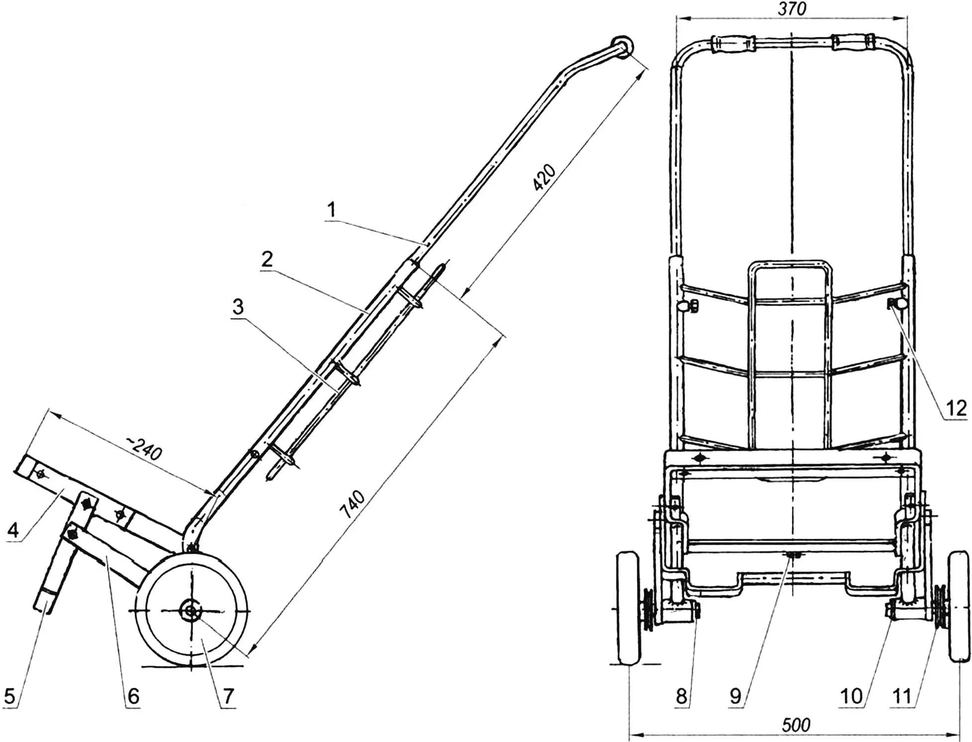
1 — telescopic handle; 2 — frame; 3 — grid; 4 — platform; 5 — support; 6 — strut (St3, s2.5, 2 pcs.); 7 — wheel (ready-made, Ø200–300 mm, 2 pcs.); 8 — axle shaft (steel 45, rod
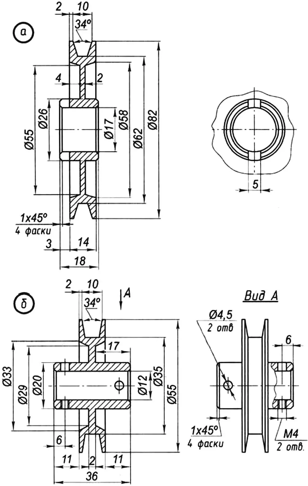
Ø15, 2 pcs.); 9 — drawbar bracket; 10 — retaining ring (Ø2, 2 pcs.); 11 — drive pulley (2 pcs.); 12 — set screw M5 (2 pcs.)
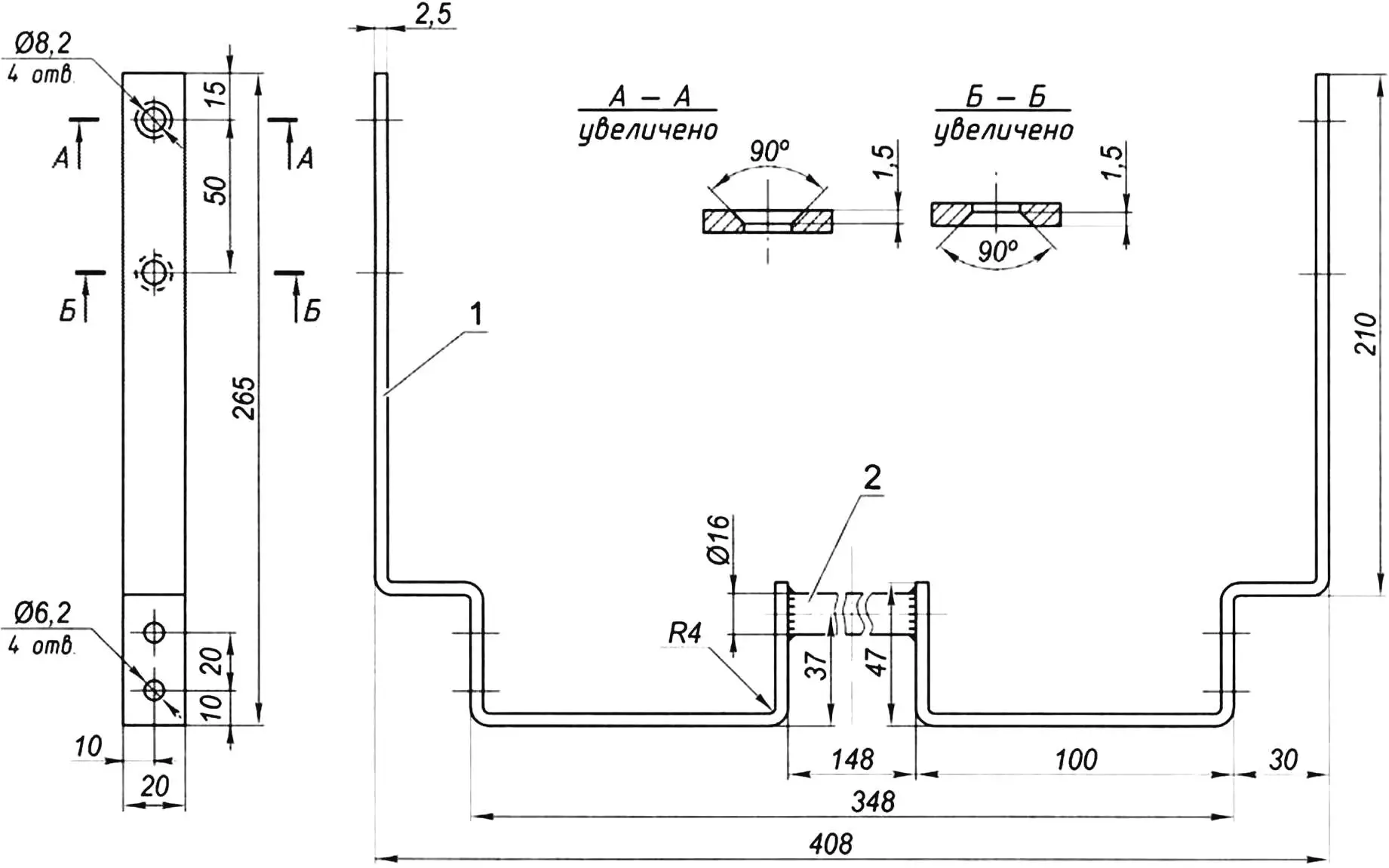
The unit’s cart is similar to utility carts available on the market; a suitable one can even be adapted for the unit. It consists of the following parts, or rather subassemblies: handle, frame mounted on two wheels, and a platform with support and struts hinged to it. The frame base is a pair of uprights from tube sections 20 mm in diameter with 1.5 mm wall thickness. They are connected by a grid welded from 8 mm round rod. The grid is three crosspieces joined by a rectangular frame. For convenient load transport on the cart, the grid is slightly recessed inside the frame. The handle is U-shaped from 16 mm outer diameter tube — slightly smaller than the inner diameter of the longitudinal tubes into which it is inserted by its tipped ends. If the clearance between upright tubes and handle is small, tips can be omitted. Furthermore, to simplify the design, the upright and handle can be made as one part.
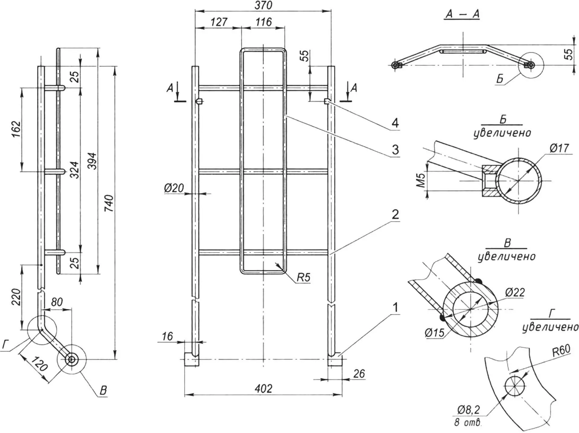
1 — wheel hub (steel; tube 22×3.5; 2 pcs.); 2 — upright (steel; tube 20×1.5; 2 pcs.); 3 — grid (rod Ø10); 4 — threaded nipple M5
Minimum cold-bend radii for the tube diameters used are 70 mm and above. To achieve the required radii, tubes must be heated at bends or given triangular cutouts to mid-wall and then welded. In use, handle length can be adjusted to the “driver’s” height and fixed with M5 set screws; for storage the handle can be fully retracted into the longitudinals. Rubber grips on the handle crosspiece improve control.
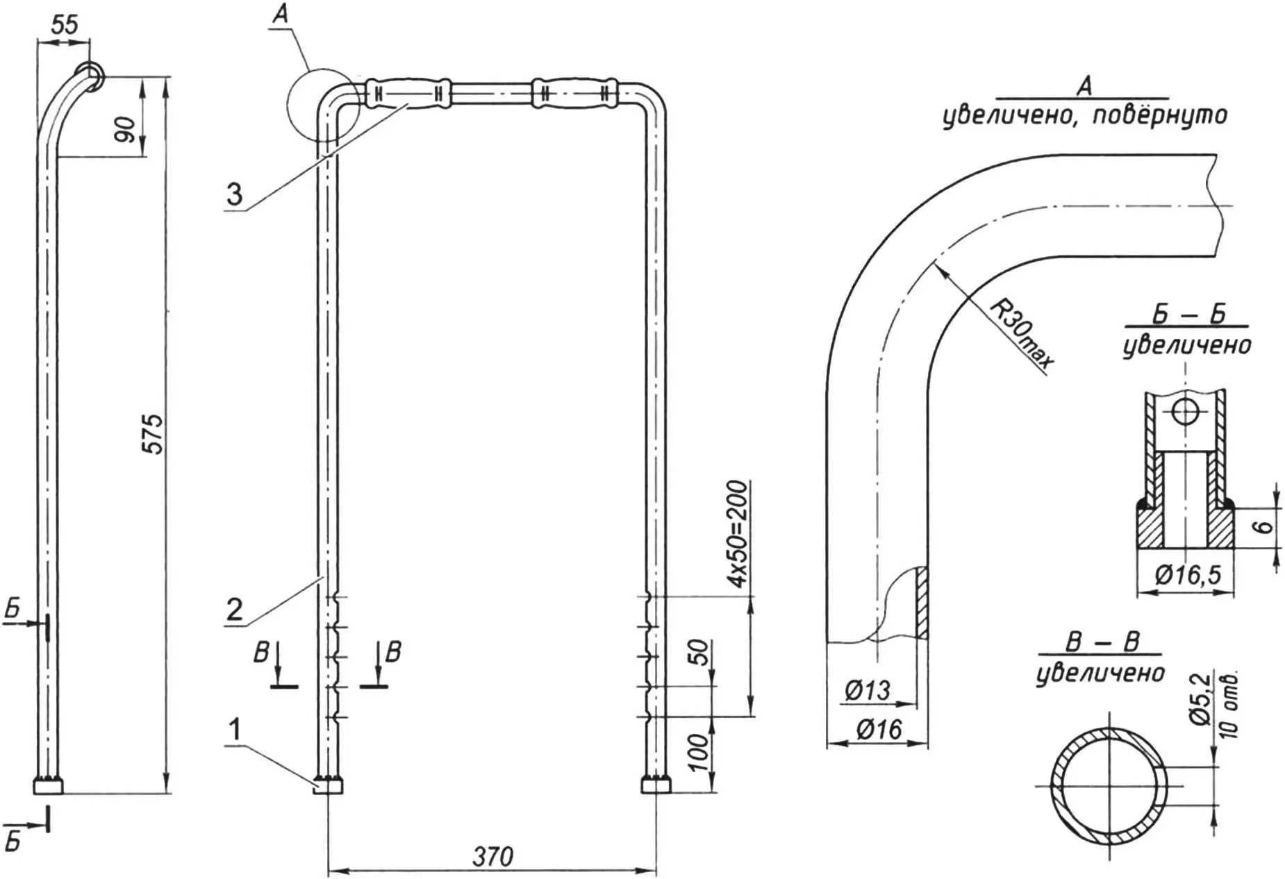
1 — tip (steel; rod Ø17; 2 pcs.); 2 — handle (tube 16×1.5); 3 — grip (rubber, 2 pcs.)
The platform is hinged to the frame uprights at their lower bend on the inner side. The support ends are also hinged to the platform sides, and the strut ends to the support sides in the same way. The other strut ends are fitted on the wheel half-axles and can rotate about them. The platform and its support are subassemblies.
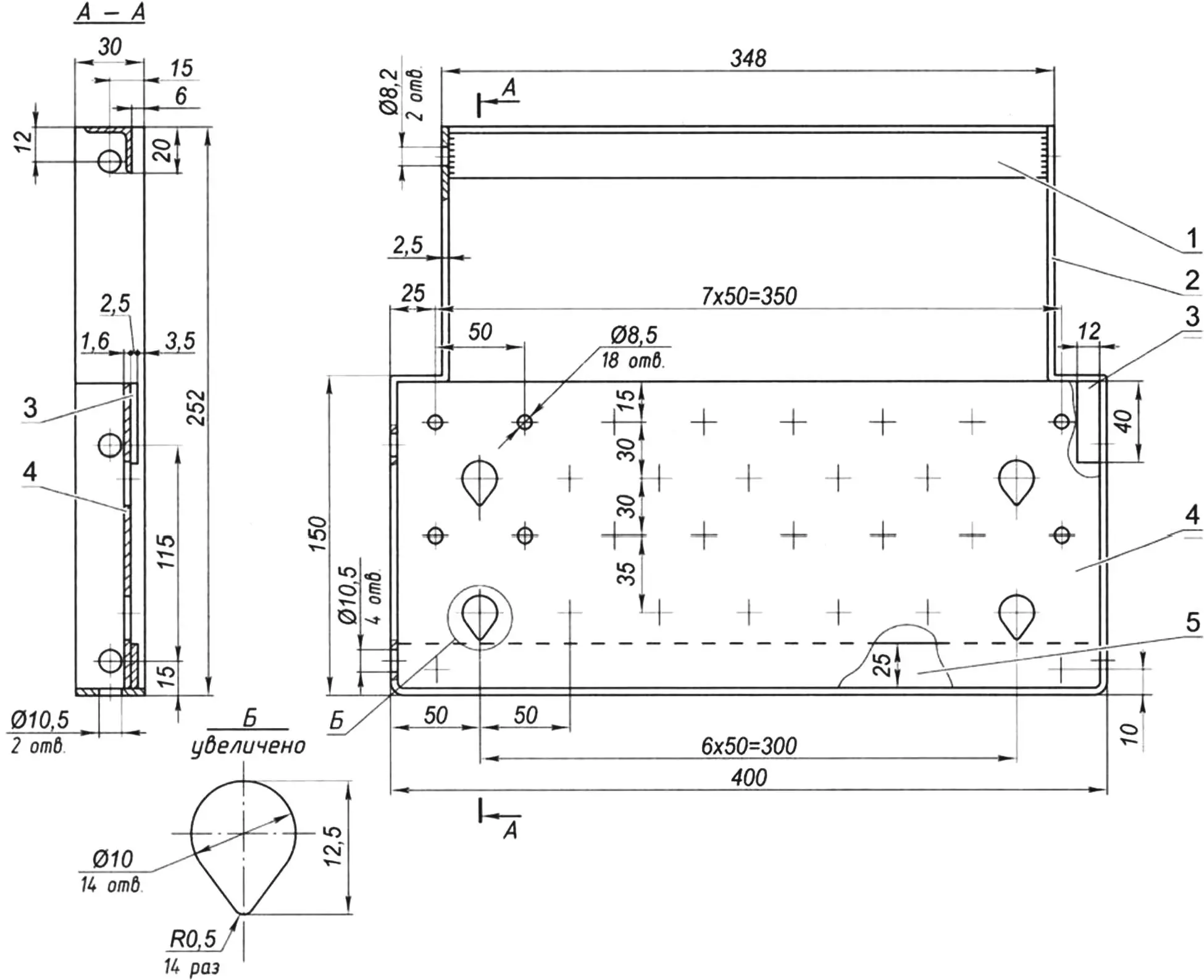
1 — crosspiece (steel, angle 20×20); 2 — frame (St3, strip 30×2.5); 3 — gusset (St3, sheet s3, 2 pcs.); 4 — deck (St3, sheet s1.6); 5 — support plate (St3, strip 25×2.5)
The platform frame is a shaped bracket bent from 30×2.5 mm steel strip. Its ends are welded to a 20×20 mm angle crosspiece between them. Gussets in two corners and a 20×2.5 mm steel support strip on the transverse part stiffen the frame and support the deck on which seed metering units are mounted.
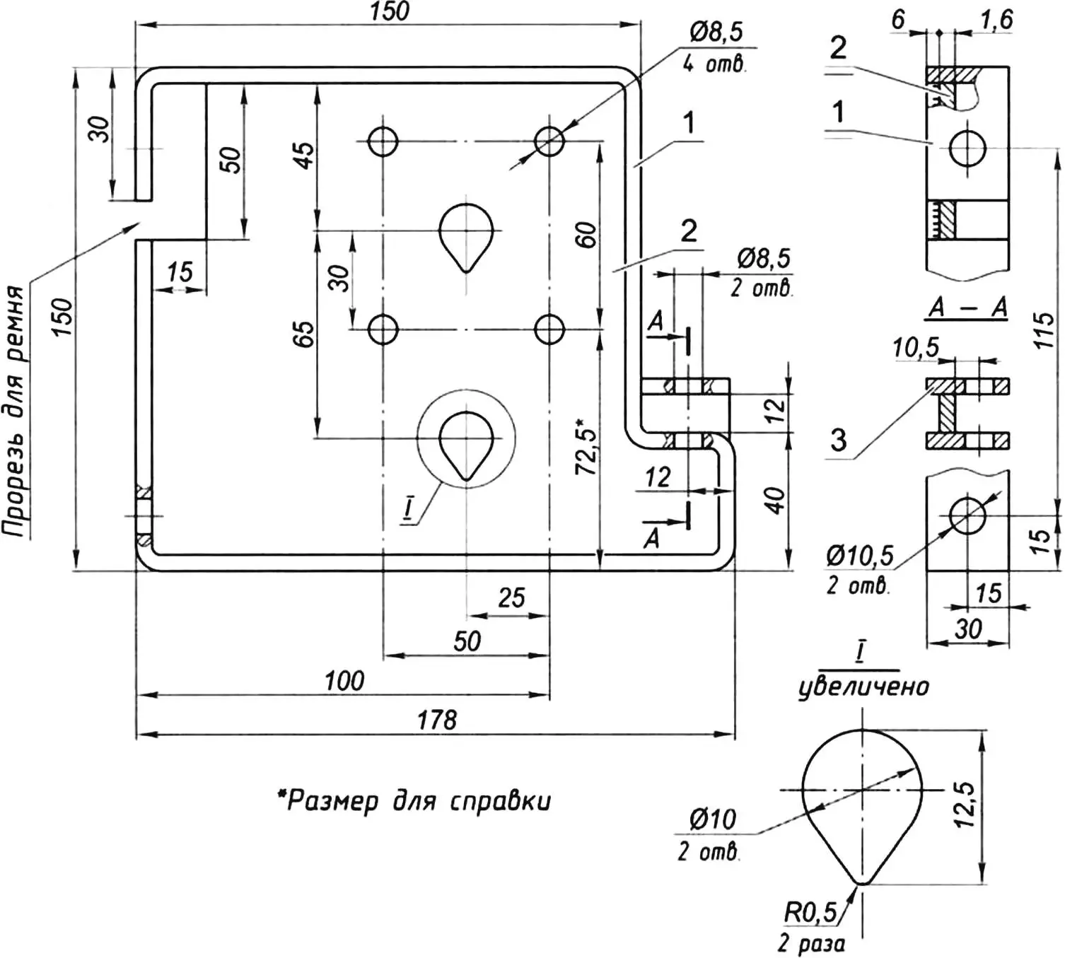
1 — frame (St3, strip 30×2.5); 2 — deck (St3, sheet s1.6); 3 — marker bar socket wall (St3, sheet s2.5)
The support is a pair of brackets bent from 20×2.5 mm steel strip, joined by a 16 mm steel tube insert; the free ends are hinged to the platform frame.
1 — bracket (St3, strip 20×2.5, 2 pcs.); 2 — connecting insert (steel, tube 16×1.5)
To move or store the cart unloaded, the platform can be raised and folded against the uprights, greatly reducing overall size. The support and struts then fold against the platform frame.
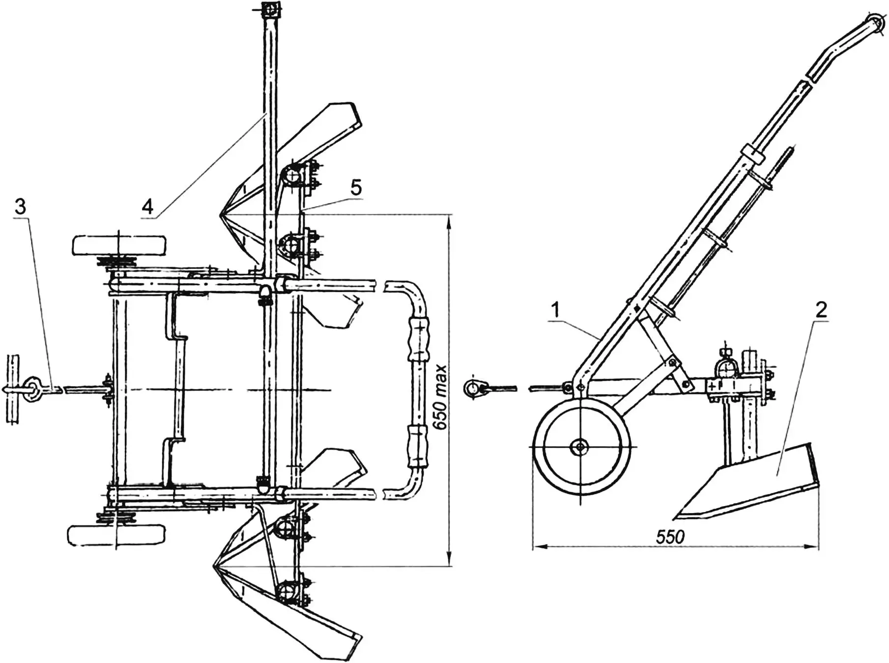
1 — cart; 2 — hiller (2 pcs.); 3 — drawbar; 4 — marker; 5 — hiller bracket
To mount farm tools, the platform is rotated 90° relative to the uprights and locked with the support and strut.
The cart wheels should be large enough — 200 mm or more in diameter with rim (tire) width at least 40 mm.
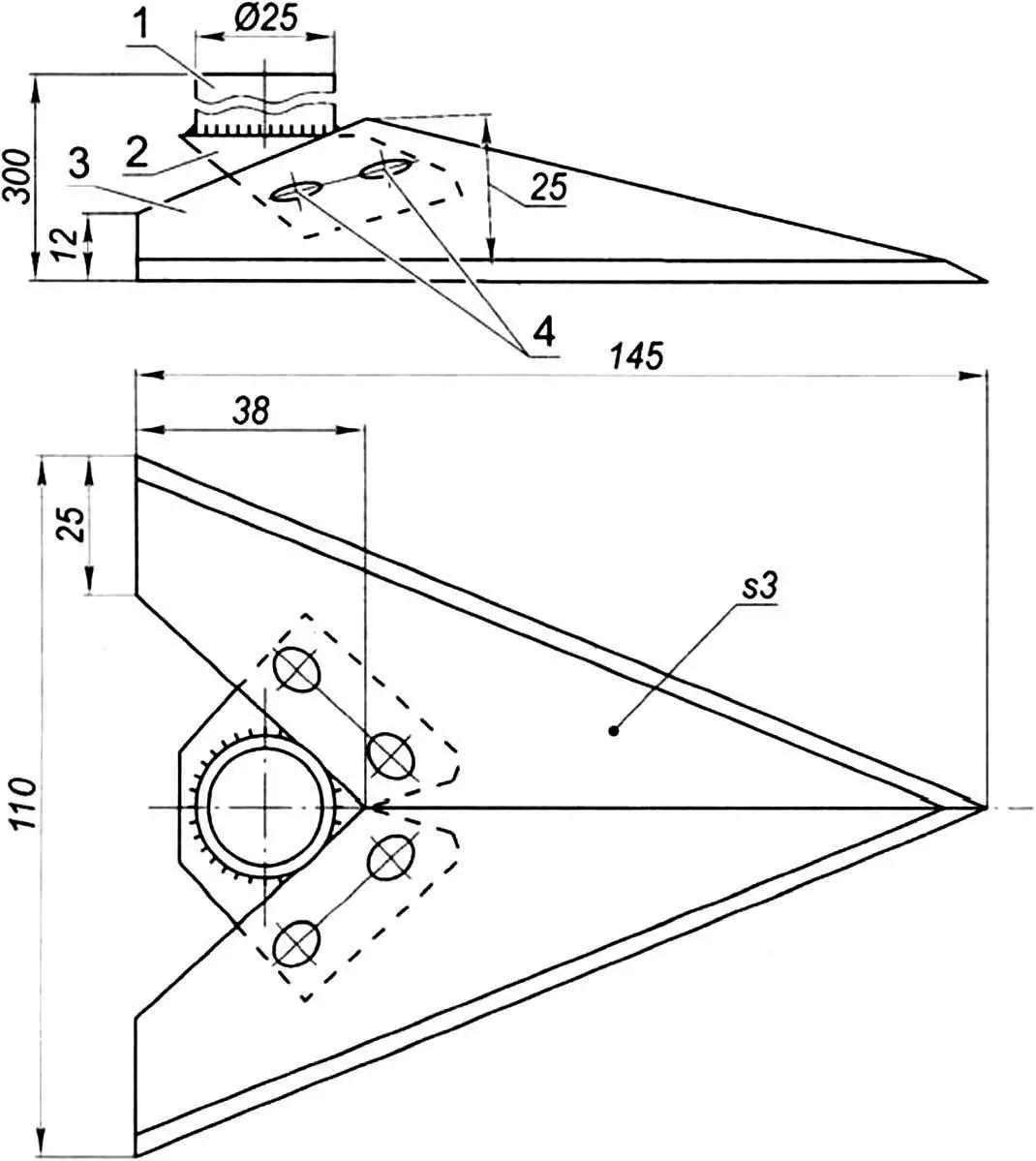
1 — opener (tube 25×3); 2 — bracket (steel, sheet s3); 3 — blade (steel, sheet s3); 4 — rivets (steel, 4 pcs.)
The unit is hand-powered; depending on the operation and soil type it is operated by one or two people. Mass of the cart with attachments is about 15 kg. Overall dimensions in working position (without markers): 1300×760×450 mm.
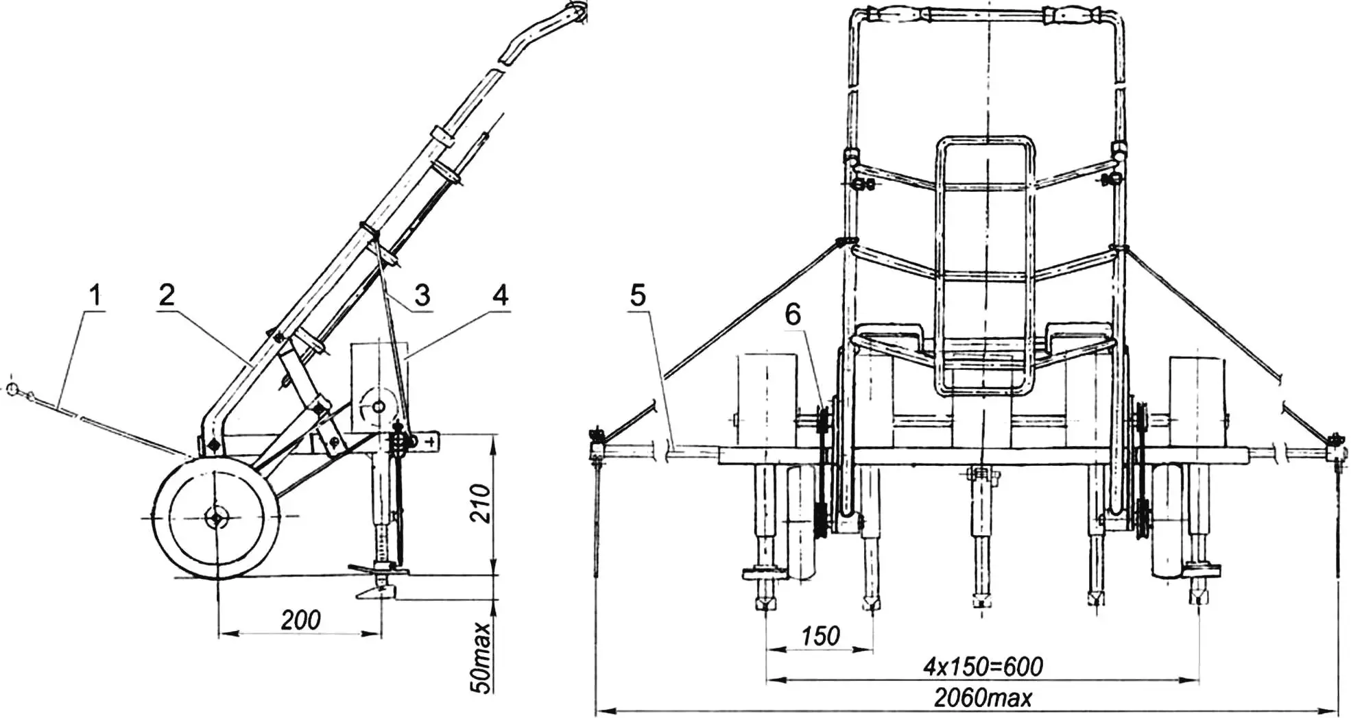
1 — drawbar; 2 — cart; 3 — stay; 4 — seed metering unit (1…5 pcs.); 5 — marker; 6 — V-belt drive (2 pcs.)
The interchangeable attachments for furrowing, hilling, and weeding are simple in design. Their construction and mounting on the cart are clear from the drawings.
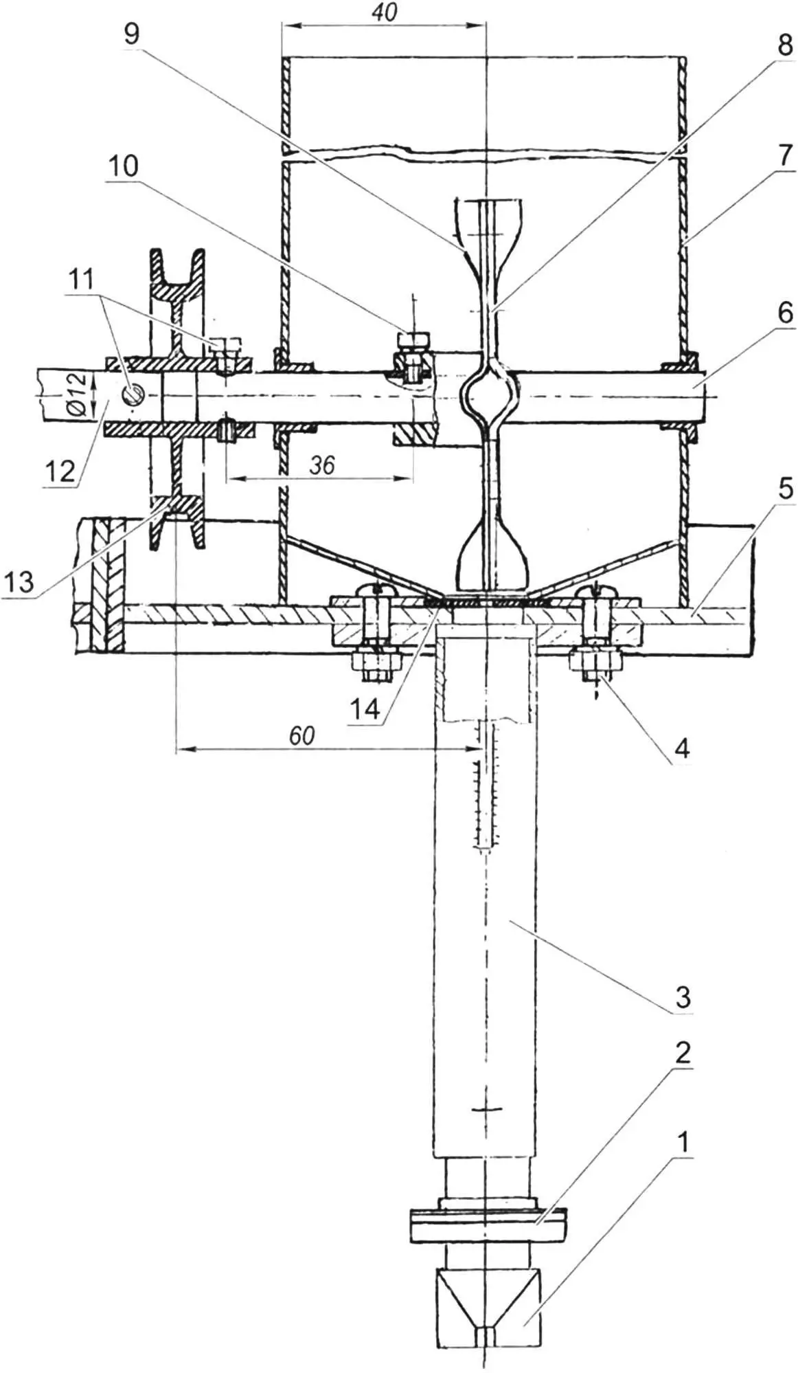
1 — seed tube; 2 — depth stop; 3 — opener; 4 — bolt M8 (4 pcs.); 5 — platform; 6 — link (steel, rod Ø12); 7 — hopper; 8 — dispenser cover; 9 — dispenser body; 10 — screw M4×10; 11 — screws M4×25; 12 — shaft (steel, rod Ø12); 13 — pulley; 14 — shutter (steel, sheet s0.7)
The most complex attachment to build is the precision (drill) seeder. It consists of several modular blocks assembled with sufficient accuracy from well-fitted subassemblies and parts: hopper, dispenser, opener, seed tube, depth stop. The heart of the seeder is the rotating dispensers. Drive is from the cart wheels via V-belt and a common shaft. An important design point is choosing the drive ratio i of this transmission. Together with wheel diameter Dk and number of dispenser cells n, it determines seed spacing T.
T = π×Dk wheel/ixη, where:
i = D/d;
d — drive pulley diameter;
D — driven pulley diameter;
Dk — wheel diameter.
To change seed spacing (it varies by crop; recommended values for common crops are in the table), replace pulleys so that their ratio gives the required spacing.
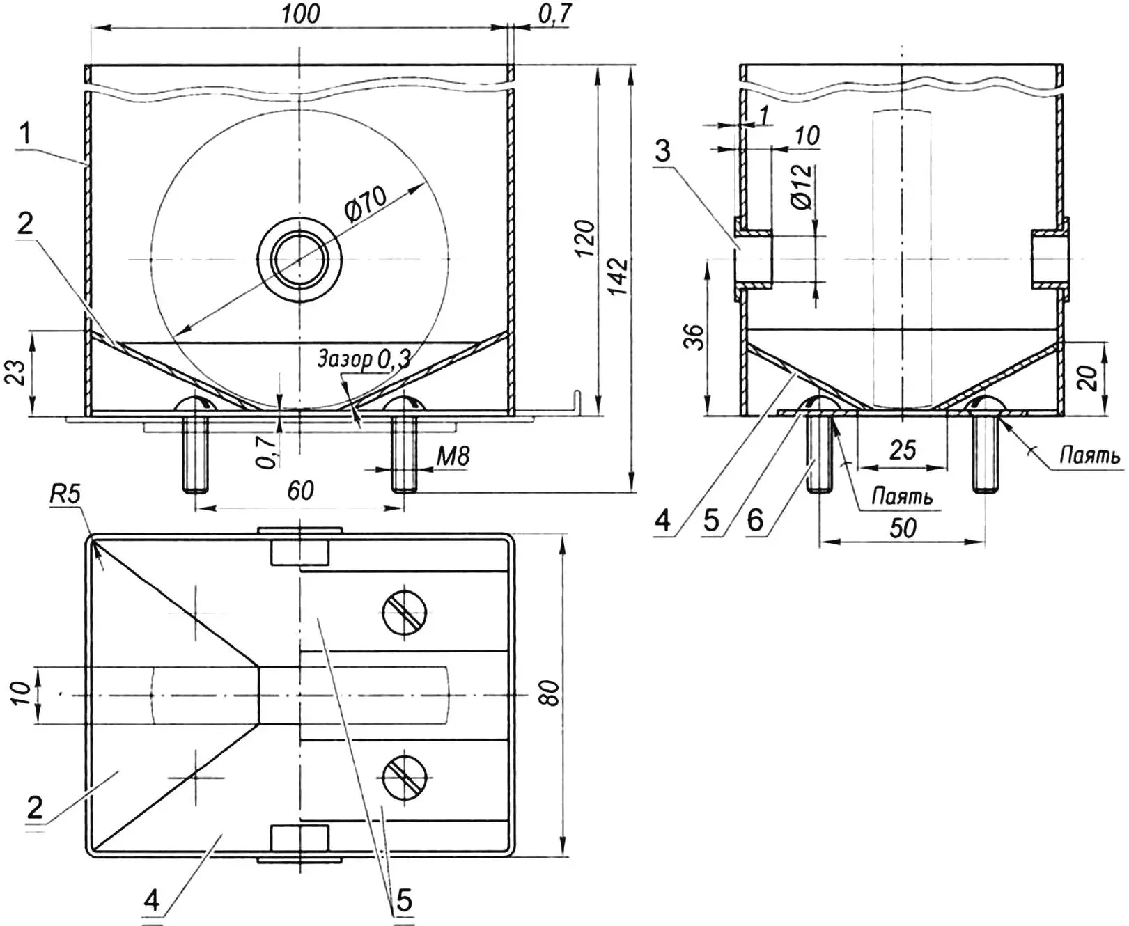
1 — shell; 2 — side (2 pcs.); 3 — bushing (Br.OTS-5-5, 2 pcs.); 4 — wall (2 pcs.); 5 — plate (St3, sheet s1, 2 pcs.); 6 — screw M8×25 (4 pcs.)
Although all dispensers share one shaft, for smoother operation the V-belt drives to it are best taken from both wheels.
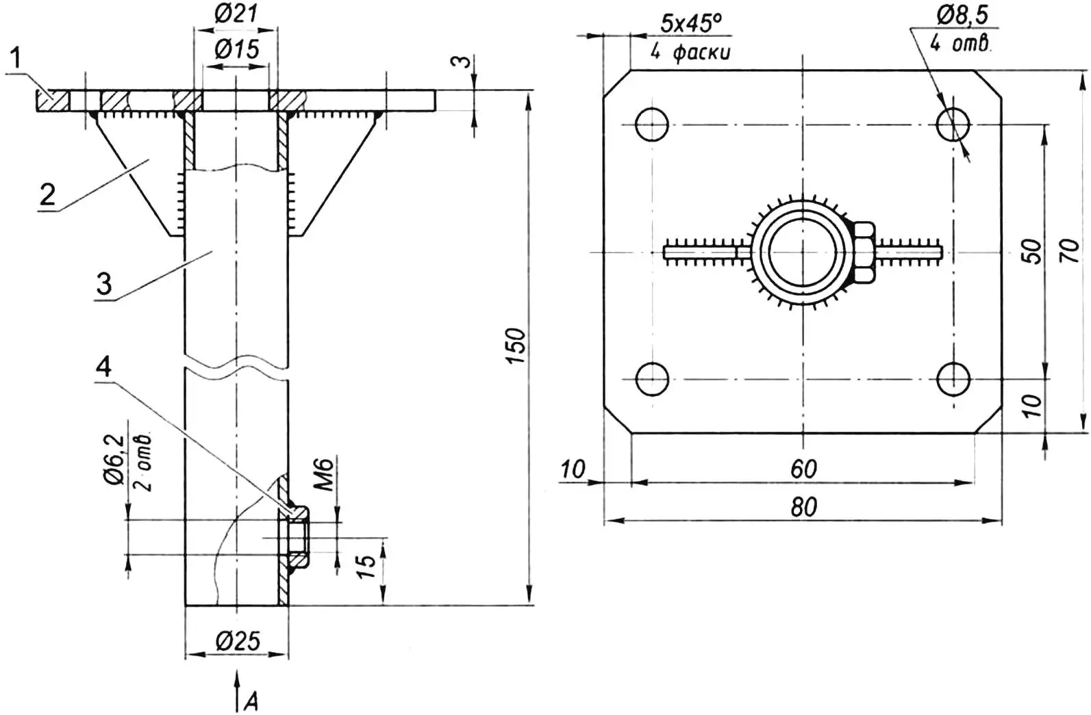
1 — plate (steel, sheet s3); 2 — gusset (steel, sheet s3, 2 pcs.); 3 — upright (steel, tube 25×2); 4 — M6 nut for seed tube mounting screw
So that only one seed enters each dispenser cell, cell inlet size can be adjusted (depending on seed size) by shifting the cover relative to the body.
| Crop | Row spacing, cm | Sowing depth, cm |
|---|---|---|
| Onion | 1.5–2 | 2–3 |
| Carrot | 2–3 | 2 |
| Cabbage | 3–4 | 2–3 |
| Dill | 3–4 | 2–3 |
| Sorrel | 3–4 | 2–3 |
| Radish | 3–4 | 2–3 |
| Spinach | 4–5 | 2–3 |
| Celery, parsnip | 6–8 | 3–4 |
| Peas, beans | 10–13 | 3–4 |
| Pepper (seedlings) | 6–8 | 2.5–3 |
| Lettuce | 6–8 | 2.5–3 |
| Eggplant | 6–8 | 2.5–3 |
From one to five seed metering units can be mounted on the cart platform at 50 mm spacing. To fit the maximum number of units (five) at the largest seed spacing (150 mm), auxiliary platforms are attached to the sides, each carrying one unit.
1 — leg (steel, tube 20×1.5); 2 — wedge (steel, sheet s2.5)
1 — collar (steel, tube 25×2.25); 2 — foot (steel, sheet s1.6)
Sowing depth is adjusted by moving the seed tube relative to the opener and the depth stop relative to the seed tube.
1 — galvanized plate (steel, sheet s0.7); 2 — body (galvanized steel, sheet s0.7); 3 — hub
Depending on seed spacing, different disks with 2, 4, or 8 cells are fitted to the dispenser and the outlet size is changed. A check of seed output is done on a cloth- (or tarp-) covered area. Close the outlet with the shutter, remove the seed tube, fill the hopper with seeds. Then partly open the shutter and move the cart over the area, checking spacing and adjusting as needed.

«Modelist-Konstruktor» No. 11’2009, V. HORT, Kyiv, Ukraine
Recommend to read
 MOP-SURVIVOR
No matter how mounted brush for floors to handle, soon she still gets cranky, and there, staring, and start to come off. This will not happen if the connection is at once strengthened by... WINGED JEEP
The passenger plane the Yak-12. For many worldwide known aircraft designers and their teams, the road to big aviation began with the creation of a light aircraft. Often, these are the...
