PROFILE ONLY

PROFILE ONLY(THE BUILD-POLYOPIA). Building the model-polyopia begin with the manufacture of the fuselage (Fig. 1), the contours of the lateral projection should most accurately reflect the similarity with the copied aircraft. To the fuselage structure demands maximum strength with minimum weight. The greatest difficulty in its manufacture is the reduction in the weight of the tail, which is much longer than the front, So it makes truss.

 
Manufacturer of tail farm is complicated by the necessity of mutual adjustment of parts and glued together. The upper and lower shelf — made from pine slats with a thickness of 3-4 mm and a width of 8-12 mm (on the forward fuselage). It is desirable that the cross section of the rails to the end decreased. The thickness of the diagonal struts 1-2 mm, a width equal to the width of the shelves in this place. The space between the shelves instead of diagonal struts completely to fill light foam. The farm ends with a boss. All the parts of the fuselage are connected by a glue-PVA or epoxy resin. The length of the joints of the shelves and the bow shall be not less than 30 mm.
 
So how to worry about facilitating the forward fuselage and its strength is not necessary, it is made from a monolithic block of wood. Sometimes the bow of paste over with a cloth or fiberglass glue or resin. This reduces the fragility of the pine plates.
Special attention should be paid to the conformity of the contour of the vertical tail — fin and rudder (Fig. 2), as they serve as a kind of autograph, the design Bureau that created this plane.
 
Keel with rudder — wooden plate with a thickness of 1-2 mm. Handlebar denied the right by 10-15° to the tension cords in flight and stiffening of the vertical stabilizer.
 
The stabilizer and the Elevator, too, from wood plate thickness of 2-3 mm. Front edge rounded, rear is reduced to a thickness of 0.5—1mm. All this to reduce drag and weight. Movable Elevator, usually installed only on one half of the stabilizer. This is quite enough.
 
Fig. 1. The design of the fuselage of the model-polyopia
 
Fig. 1. The design of the fuselage of the model-polyopia:
 
1 — front (wooden plate), 2 — cabin (Plexiglas, celluloid), 3 — truss the tail part, 4 — lug rear, 5 — shelf-spar, 6 — brace, 7 — place bonding (wrap the thread), 8 — cutouts for the wing spars.
 
Fig. 2. The shape of the keels, typical for aircraft of various types.
 
Fig. 2. The shape of the keels, typical for aircraft of various types.
 
Fig. 3. Alignment and balancing models
 
Fig. 3. Alignment and balancing models:
 
1 — weight (20 g), 2 — rudder, 3 — pull, 4 cords.
 
Fig. 4. The motor mount on the model-polyopia
 
Fig. 4. The motor mount on the model-polyopia:
 
1 — a bolt M3, 2 — plate, 3 — nut M3, 4 — spring washer.
 
Fig. 5. Installation of the propeller
 
Fig. 5. Installation of the propeller:
 
1 — spinner, 2 — blade, 3 — engine, 4 — thrust washer 5 — washer.
 
Fig. 6. The decoration of the forward fuselage.
 
Fig. 6. The decoration of the forward fuselage.
 
Before attaching the feathers, you should check the centre of gravity of the fuselage with installed engine and attached tail. It needs to be at the leading edge of the wing. Otherwise, it is necessary to take measures to facilitate the farm and tail (Fig. 3).
 
The engine is attached to the model (Fig. 4) with four bolts with nuts. Under both nuts, so they do not cut into the wood, it is necessary to build a common metal plate with a size of 10×20 and a thickness of 1.2 mm.
 
Fixed nuts with lock nuts. Models of aircraft with nose wheel landing gear is secured by a clamp under the same nut. To move the center of gravity of the forward fuselage instead of the hex nuts securing the propeller, put the steel of the COC (Fig. 5) with internal thread on the motor shaft and a transverse hole for the tightening knob.
Sometimes the nose of the fuselage opposite the engine, hang thin plywood, which covers the cutout under Carter. On this side draw or paste the exhaust nozzles of the aircraft engine (Fig. 6). The canopy (Fig. 7) is usually made of transparent celluloid or Plexiglas. Celluloid inside the lantern, you can insert the image of the head of the pilot.
 
Farm fuselage glued paper after mounting of the tail and pre-balancing model complete with engine and propeller. Then proceed To the manufacture of the wing.
 
A typical feature of wing structure model-polyopia is a Central plywood spar with a thickness of 2-3 mm (Fig. 8), which provides a solid connection of the wing to the fuselage and the transmission from the chassis (on most aircraft they are installed on the wing). The height of the plywood spar is the same as the ribs at their intersections, or slightly less.
 
The form takes into account the transverse V – wing. Rib cut in the longitudinal one-third of its height. Cut ribs usually from the bottom, side rail top.
 
Fig. 7. Lantern cockpit And monolithic (plexiglass), B — laminated celluloid.
 
Fig. 7. The lantern of the cockpit:
 
A — monolithic (plexiglass), B — laminated celluloid.
 
Fig. 8. Mount the landing gear to the wing spar
 
Fig. 8. Mount the landing gear to the wing spar:
 
1 — fuselage 2 — thread and glue, 3 — landing gear (wire), 4 — longitudinal.
 
Fig. 9. Rib wing
 
Fig. 9. Rib wing:
 
1 — center spar (plywood), 2 — shelf rails (pine) 3 — rear edge of the wing, 4 — rib, 5 — the leading edge.
 
Ribs (Fig. 9) cut a jigsaw out of plywood with a thickness of 1 mm or phony veneer. Thin fake plates are sawn off on a circular saw and processed to make the surface of sandpaper glued on a flat wooden block with a length of 200-300 mm and a width of 50-60 mm.
 
In addition to power short plywood spar across the wing is the spar dvukhpolosnykh connecting all the ribs and wing tip. It consists of two pine slats, which are inserted from the top and bottom of the ribs into the corresponding grooves. Fabricate the front and rear edges of the wing. The front, usually square, inserted in cutouts in ribs socks on glue, back, of triangular cross-section, has the cuts they impose, the pre-fluff glue the tails of the ribs. Cuts have to do with a depth of one-third edge and the thickness of the tail rib.
 
The wing tips (Fig. 10) from wooden plates or wedges of foam processed with a knife and sandpaper.
 
First glued one half of the wing, and after complete drying, – the second. The assembled wing is mounted on the fuselage (Fig. 11), the power spar is inserted into the corresponding slot in the fuselage and secured with glue. Shelves longerons and the front edge is glued on the plywood parts. During installation not forget to install the root (adjacent to the fuselage) ribs. These parts are only for fixing the covering of the wing and can be greatly facilitated internal cutouts. The angle of the wing zaklinanija must be strictly adhered to and to be constant throughout the scale — distortions are eliminated. Transverse V – wing is symmetrical relative to the plane of symmetry of the fuselage.
 
After the wing mounted gear and empennage (Fig. 12). The stabilizer is put on the farm of the fuselage or hit the boss (depending on aircraft design and drawing models). At the junction of the fuselage and the stabilizer top and bottom for strength bonding laid triangular amplifiers (side of triangular cross-section 2-3 mm), after drying, the adhesive dioscuriada. Keel and rudder are installed after the stabilizer.
 
Landing gear (Fig. 13) schematically replicate the real aircraft. So, the La-5, Yak-7, Yak-9 stand straight, and the Yak-1, Yak-3 as if round the wheel, on the Il-2 “foot” of the chassis — two. Rack — steel wire Ø 2,5—3 mm — fastened to the plywood spar thread on glue. In the spar drilled a few holes in it, and stand as if sewn. In the opening rack of the plane of the wing to the spar and the rib is glued to the plywood rectangle to it is attached the cording.
The wheel is usually made of foam (Fig. 14). A hole in it for the axis is drilled after gluing on both sides a reinforcing plywood plates 3 mm thick To reduce friction in a wheel is inserted into a copper or tin (bent from strips of sheet metal) tube. Without reinforcement of the side plates, the wheel model, despite the presence of the sleeve melts and begins to touch the rack.
 
Side of the wheel is sealed with a circle of construction paper that hides defects in the installation of lining, mimicking the drive wheels of foam rubber conform more to the prototype, but require special care — they are “afraid” of fuel from the engine.
 
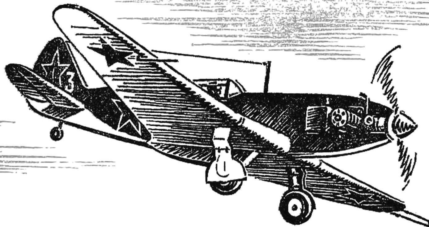
On the real aircraft stands installed flaps covering the hatches of the landing gear. Characteristic of the plane shape must be repeated on model.
 
The control system (Fig. 15) consists of two flexible rods made of steel wire Ø 0,6—0,7 mm, tripledeal dural (S = 1.5 mm) of the swing, the axis of which revolves in the ears attached to the fuselage bracket and wooden end with two wire Ø 1.5 mm tip, aluminum rocking chair, riveted to the steering wheel height, plywood or wire guides on the left wing for the passage of tie rods (POS. 6). These guides are located at 20 to 30 mm behind the center of gravity of the model. In flight the fuselage should not be directed tangentially to the trajectory and nose out of the circle. It is necessary for the tension cords, that is, provide reliable Elevator control. So the model does not roll inside the circle under the weight of the cord or from the occasional gust of wind, the external right-wing heavier load 20-30 g of the rocking Bracket can be installed on either side of the fuselage, but for aesthetic reasons (the desire to maintain a large number of copies per cell on the left side) motor unit with tank, rocking chair, thrust and Elevator are located to starboard, and in the fuselage drill two holes for the passage of the flexible rods.
 
After installation of all units of the model again determines the location of its center of gravity. It needs to be ahead of the first quarter chord of the wing.
 
Fig. 10. Versions of the wing tips
 
Fig. 10. Versions of the wing tips:
 
1 — hard shell, 2 — the ending of the wooden plate, 3 — the ending of the foam.
 
Fig. 11. Installation of the wing relative to the fuselage before gluing.
 
Fig. 11. Installation of the wing relative to the fuselage before gluing.
 
Fig. 12. Installation horizontal and vertical stabilizer on the fuselage of the model
 
Fig. 12. Installation horizontal and vertical stabilizer on the fuselage of the model:
 
1 Kil, 2 — glue, 3 — horizontal tail, 4 — beadings, 5 — fuselage.

 
Fig. 13. Options for landing gear for aircraft of various types.
 
Fig. 13. Options for landing gear for aircraft of various types.
 
Fig. 14. Wheel
 
Fig. 14. Wheel:
 
1 — “disc” (drawing paper), 2 — metal tube-bushing, 3 — wheel (foam).

 
Fig. 15. The elements of the management system model
 
Fig. 15. The elements of the management system model:
 
1 — rocking chair, 2 — winding (thread) and glue, 3 — desire (pine), a 4 — winding (thread) and glue, 5 — castle (wire solder solder POS-40), 6 — pull.
 
The slinky model paper: fuselage — micuenta or writing on the front of the wing and near the fuselage drawing, in other places — micuenta or writing. For stickers it is best to use PVA glue. Paper trim models have to cover two times with nitro lacquer an-1 (emalit), which can be replaced with a solution of celluloid in a solvent for nitropaints or acetone. The second coating is 3-4 hours after full drying of the first. To paint the model, preferably by spray or spray a liquid solution of a medium. Before painting, practice painting art on any other subject. After all, the quality of this operation depends on the final appearance of the model.
 
The typical color of military planes blue on the bottom and different shades of green or khaki top. Many of the aircraft had a top-camouflage-camouflage color stains of green and brown.
 
The red stars on the wings, fuselage and the empennage at the beginning of the great Patriotic war did not have white edging along the contour.
 
Rims usually green or gray colors, the “tires” black. The color of the tires need to be regularly restored, as the paint is erased on the ground during takeoff and landing.
 
After painting is done final balancing. The center of gravity of the finished model must be within the first quarter the width of the wing. In most cases you have to load the bow of the additional metal shims under the mounting bolts of the engine, since the rear alignment (heavier tail) model does not obey the helm of the altitude and flying erratically.
 
S. MALIK

Recommend to read

  • CHERNIHIV PATENTSCHERNIHIV PATENTS
    Children in a hurry. They are in a hurry to become adults. This children's line for the purpose of education first used, perhaps, to A. S. Makarenko. He loaded the boys a real job and...
  • SELF-SIMILAR SPORTS — WHAT IS IT?SELF-SIMILAR SPORTS — WHAT IS IT?
    When we sometimes hear the term "Automodelisme", most often remember the boys with the excitement of chasing RC cars. Indeed, in recent times RC automodel sport has become probably the...