
 Radio, powerful or low-powered — the Fox, which is so earnestly looking for “hunters” at the event. Low-power transmitters on one of the high-frequency transistor of the type ГТ308, П416. They are used for training, demonstrations, and to tune receivers. Diagram of such a transmitter operating in the range of 3.5— 3.65 MHz, — figure 1.
 The oscillator is assembled on the transistor V3. Automatic manipulation (on and off) provides the multivibrator transistors V1, V2. Coil L1 is wound on a polystyrene frame Ø 14 mm, and contains 55 turns of wire of PEL 0,35—0,41 with tap from the middle. On top of it wound coil L2 is 5 turns of the same wire.
Constant resistors — MLT-0,125. Capacitors C5, C6—KT; C1—C3 — C50-6; C4, C7 — segnetoceramic.
Power — battery 7D-0,1. The antenna is copper wire with a length of 1-5 m.
The establishment of the scheme start with the oscillator. It is collected on the sub Board and is connected to the resistor R5 minus power source.
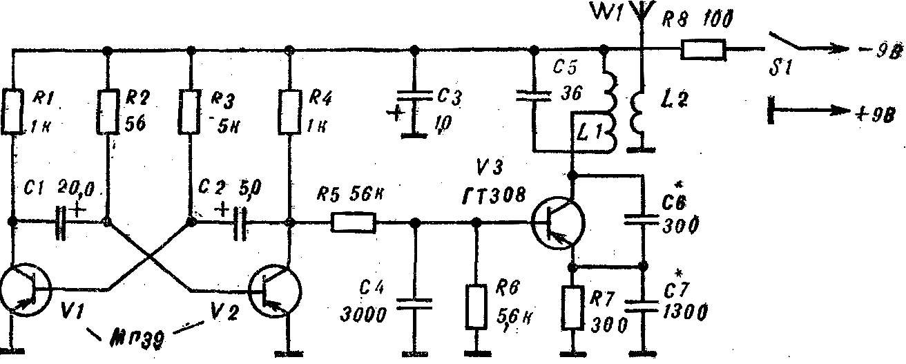
Fig. 1. A schematic diagram of a low power transmitter.
The generator is tested using the S-meter (Fig. 2). Flat coil L1 of the device, consisting of 8-10 turns of wire sew 0,51, put on the contour of the transmitter. If the generation of no, turn off the power, check the correct connection of the transistor and then the capacitor C7 is replaced by a variable with a maximum capacity of 1000 pF. Changing the value of C6 in the range 180-510 pF and rotating the knob of the variable capacitor, to achieve the stable generation of maximum amplitude of oscillation (measured by the deflection of the 8-meter).
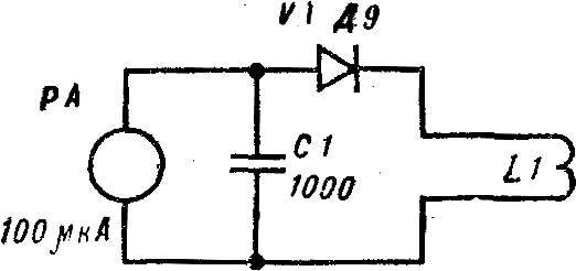
Fig. 2. Diagram S-meter.
The generation frequency depends on the capacitance of the capacitors C5—C7 and inductance L1 of the coil (40 µh). The exact value can be defined in several ways: with a test calibrated receiver, heterodyne resonance indicator (Gere) or standard signal generator, oscilloscope and a balanced mixer.
Adjustment of the multivibrator is produced by resistor R3.
The details of the configured transmitter is transferred to the two printed circuit boards (Fig. 3), while keeping an eye to the insights of the elements were carefully honored.
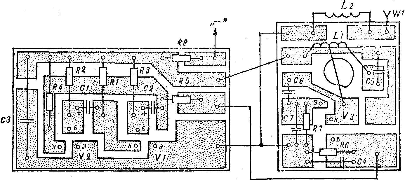
Fig. 3. PCB low-power transmitter (1 : 1).
Circuit Board housed in an aluminium case size 120X90X40 mm. In the upper part of the installed antenna output and the main switch.
Figure 4 shows the scheme of a low-power transmitter with a crystal B1 to stabilize the frequency. The oscillator operates at the moment when the transistor of the multivibrator V2 is closed. Moreover, its running time 8-10 times greater than the duration of the pause. This facilitates direction finding.
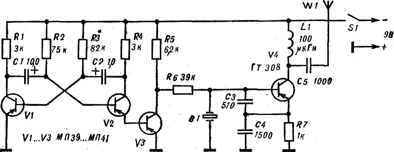
Fig. 4. A schematic diagram of a low power transmitter with a quartz resonator.
Inductor L1 is wound on a polystyrene frame Ø 6 mm, length 25 mm with a carbonyl core and contains 60 turns of wire PEV-1 0,12.
Configure this transmitter comes to the selection of the capacitance of the capacitor C4.
Figure 5 diagram of the transmitter of increased power. An oscillator transistor V1 is stabilized by quartz resonator B1. V2 — the output stage of the RF. The device is assembled on the transistor V3, is intended to indicate the adjustment of the antenna.
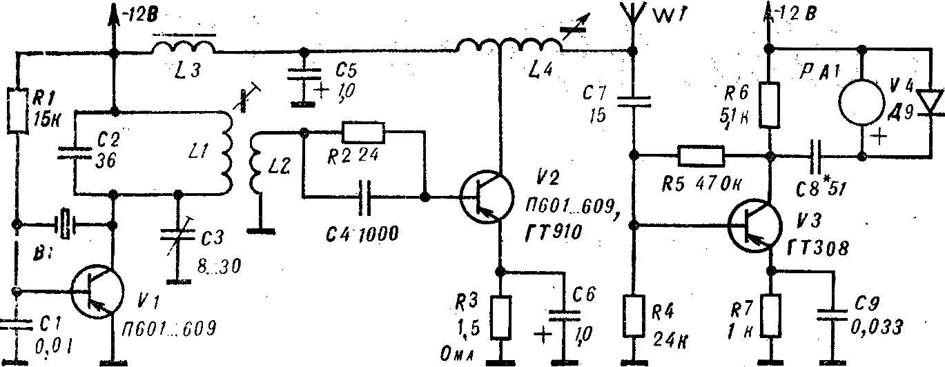
Fig. 5. Schematic diagram transmitter high-power.
Vibrations of high frequency through a current transformer L1, L2 arrive at the base of power transistor V2. In the circuit of its collector is enabled and the loop L4 with positive feedback.
The setting indicator is an amplifier of high frequency. With the collector load R6, RF voltage supplied to the PA1 milliamperemeter. Included parallel to the V4 diode rectifies this voltage.
In the transmitter circuit used power transistors direct conduction. However, you can apply and transistors n-p-n type, changing the polarity of the power reversed. In the master oscillator transistors applicable П601—П609, KT315, КТ603, КТ603, in the output stage — П601—П609 and ГТ910, КТ803, КТ903. (Recommended transistors — both types of conductivity.) Coils L1 and L2 placed in armor carbonyl core SB-(external Ø 23 mm), which, in turn, is mounted in an electrostatic screen. L1 contains 55 turns of wire sew 0,35 (44 µh inductance), L2 is located on top of L1 and contains 1 coil of a wire of PEV of 0.51. Inductor L3 is wound on the frame with inner Ø 8 mm, height 20 mm, containing carbonyl core, and has about 300 turns of wire sew 0,35 (inductance 500 µh). Coil L4 wound on a frame of the size of the regulator lines (RRS) of old TV episodes. This coil has a ferromagnetic core, exiting through the handle along the frame. Ka it is wound with 68 turns of wire sew 0,35—0,41 with the withdrawal from the 3rd round.
Circuit C2, L1 oscillator tune into resonance. Moreover, the operation that produced with deactivated output stage at reduced voltage. Indication carries the S-meter.
After the generator is configured, connect the output stage and connecting the antenna wire length
2-3 m, adjust the contour of the L4 (reduced voltage). The core of the output circuit at maximum indications of the indicator settings (2-3 mA) must be in middle position.
If in the process of adjusting the meter needle is deflected enough, and the S-meter when approaching “rolls over”, it is necessary to increase the capacitance of the capacitor C8. Current full deflection of the S-meter is 100 µa. A well-tuned and properly coordinated with the transmitter antenna consumes a current of 300-350 mA. This value depends on the connection of the driving generator with the output stage (the number of turns of L2) and matching with the antenna.
The transmitter is mounted on a printed circuit Board (Fig. 6), made of foil getinaks. Transistor V2 is installed on the radiator.
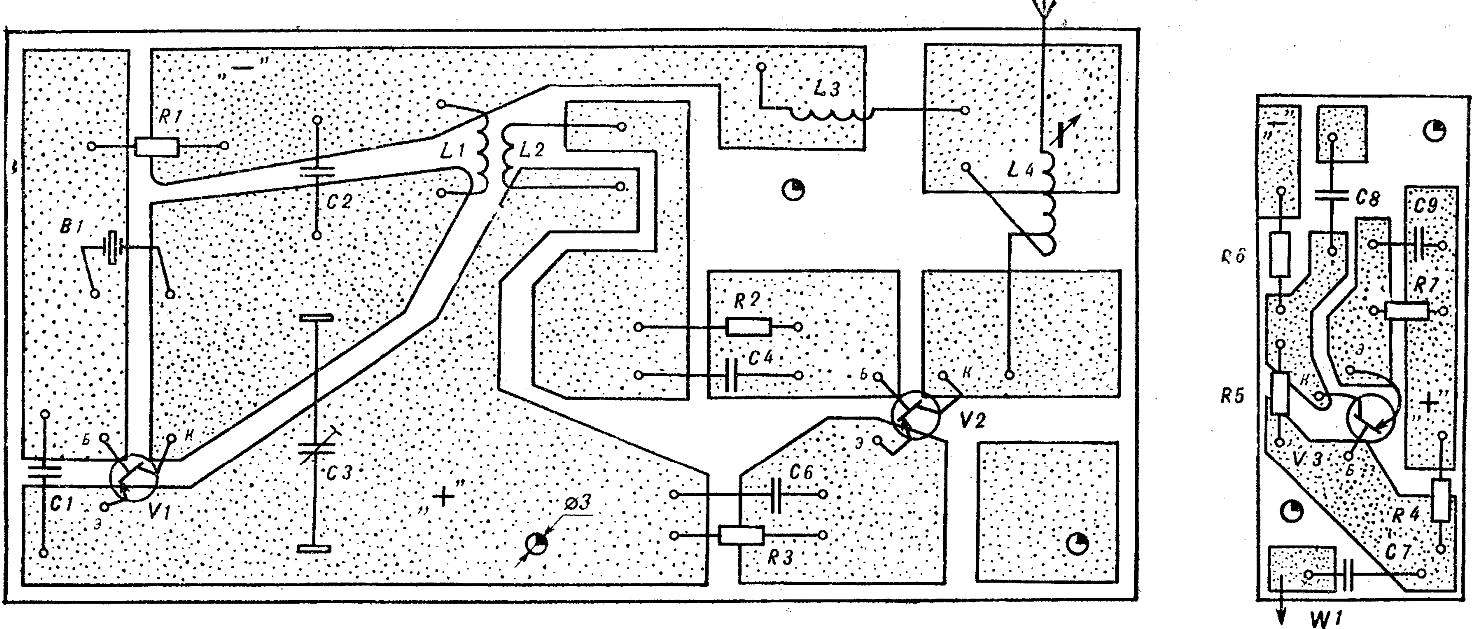
Fig. 6. PCB powerful transmitter and indicator settings (1:1).
Keying of the transmitter is carried out manually with a key or an Electromechanical interrupter (Fig. 7). The latter is a code disc with the relevant contact box made from foil fiberglass. The disc rotates by an electric motor e gear from the children’s designer. The rotation speed is set by electronic controller. Switching diagram of a transmitter and manipulators in figure 8.
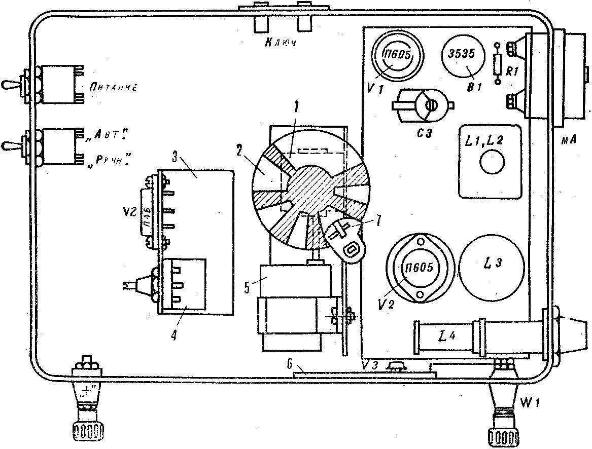
Fig. 7. The deployment of elements of the transmitter in the housing:
1 — reducer, 2 — code disc, 3 — voltage regulator 4 — variable resistor, 5 — motor, 6 — Board adjustment indicator, 7 — collector.
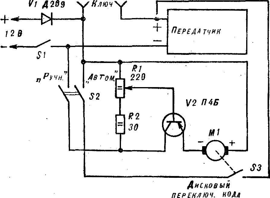
Fig. 8. Switching diagram of a transmitter and manipulators.
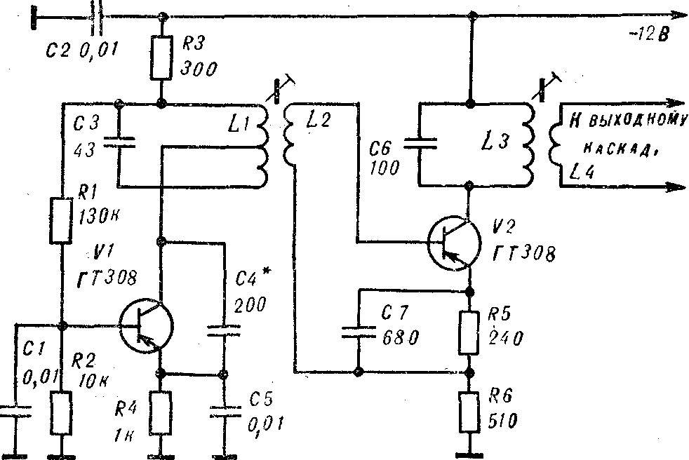
Fig. 9. Diagram of the oscillator.
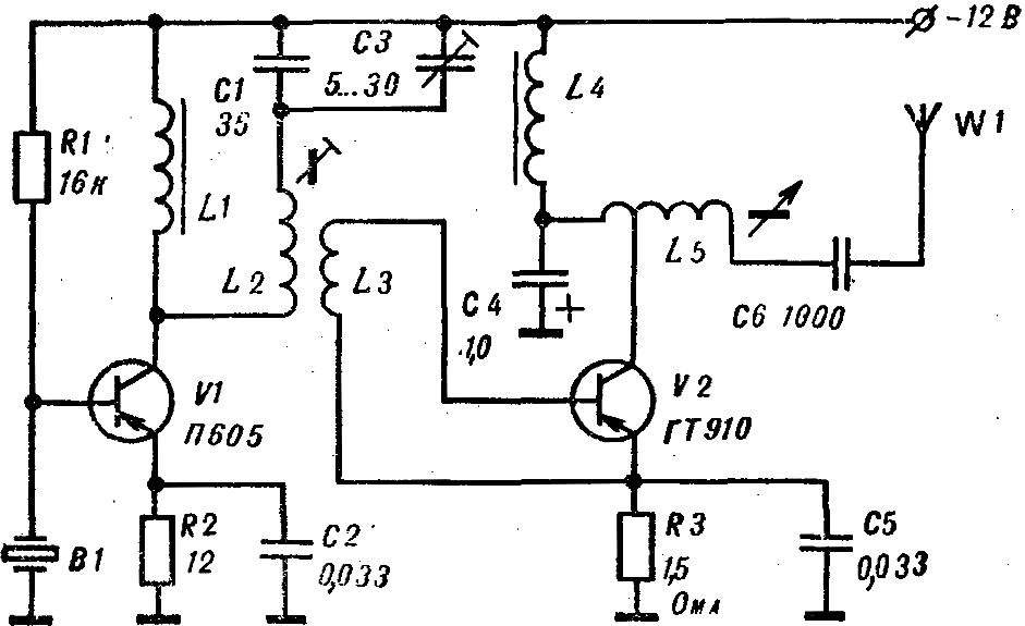
Fig. 10. A schematic diagram of a powerful transmitter.
Instead of the oscillator with a quartz resonator can be used the oscillator with a buffer stage (Fig. 9). Coil L1 consists of 36 turns of wire sew 0,35 with tap from the middle. On top of it wound coil L2. It contains 12 turns of the same wire. L1 and L2 are placed in the armor carbonyl core SB-1A, which, in turn, is mounted in an electrostatic screen and aluminum casing.
Coils L3 and L4 are placed in the armor carbonyl core SB. The first contains 36 turns of wire sew 0,35. On top of her wound 3 coil L4 of the same wire. The core is installed in an electrostatic screen.
Figure 10 shows the scheme of a powerful transmitter for “Fox hunting” with a quartz resonator. Coils L1, L4 are wound on the frame with inner Ø 8 mm, height 20 mm with carbonyl core and contains 300 turns of wire sew 0,35 (inductance 500 µh). Coils L2 and L3 are located in armored core SB-placed in an electrostatic screen. L2 contains 55 turns of PEV-1 of 0.35. On top of it wound 1 coil wire mgshv 0,35.
Coil L5 contains 55 turns of wire sew-1 0,35—0,41 with the withdrawal from the 3rd round and wound on the frame of the RRS of old TV sets.
A. PARTIN, master of sports of the USSR, Sverdlova
Recommend to read
 PAINTING “MATRYOSHKA”
During repair work the goats are not always required, so many people prefer to do without them, making a pyramid of chairs, stools and table. At the same time, there are various... “SHERMAN” WITH “LONG HAND”
The defeat of the English troops on the European continent and the loss of almost two thirds of their tanks forced the British to seek the assistance of the United States. To make up for...
