
 Once his hands were wound transformer coils, he knows how difficult, unproductive and laborious this work. It is necessary not only to carefully, turn to turn, put the wire on the frame, but do it with the necessary — is the same for all coil — tension and not make a mistake when counting turns.
 A good helper in this labour-intensive business can become semi-automatic winding machine: it will count the number of turns, will ensure the necessary tension of the wire and gently laid his turn to turn. You can do it in any circle. All items are homemade, with the exception, of course, the motor (such as DAG) and a Cycling meter speedometer.
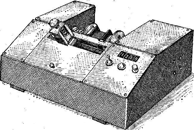
Components and parts of the machine are mounted in a housing, assembled from plywood with a thickness of 5-8 mm or sheet aluminum thickness 2.5—3 mm. Its structure and main dimensions are shown in figure 1. Plywood panels of the hull are joined with adhesive strips and small studs, and metal — dural corners and the M3 screws.
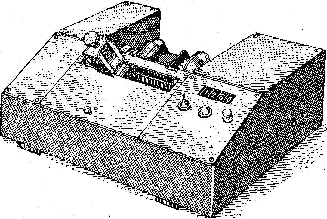
Fig. 1. Semi-automatic winding machine for transformer coils.
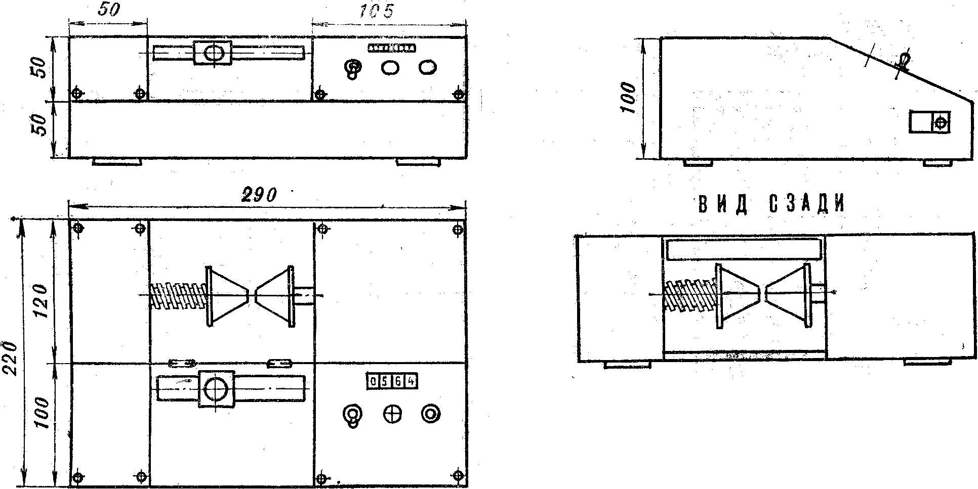
Fig. 2. Diagram of lathe and its main dimensions.
On the right panel mounted rocker switch on engine button short operation of the motor, signal lamp and count number of turns.
The motor is attached to the inside right wall of the housing by two bolts. Its axes are fixed trerosewill pulley, machined aluminum.
The frame of the transformer is mounted between two centering pyramids; one of them (on the picture left) is spring loaded and provides the clamping frame to the other, leading. On the axis of the latter is a slave pulley connected with the pulley motor rubber pasik. Driven pulley, as host, has three working stream for the selection of optimal gear ratios and one additional accounts associated rubber pasik with a pulley on the counter of the speedometer. The gear ratio of the last pulley should be adjusted experimentally: the fact that velocitometer produced under different wheel at each revolution of the shaft of the counter has different change the scoreboard.
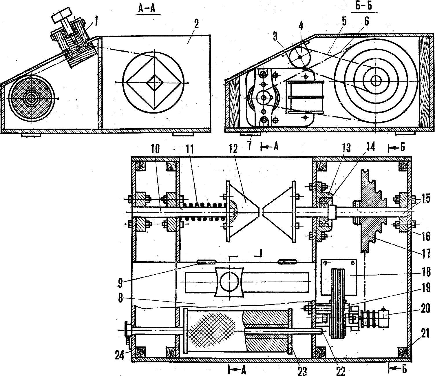
Fig. 3. The layout of the winding machine:
1 — stacking mechanism, 2 — body, 3 — meter (velocitometer), 4 — the pulley of the counter 5 — rubber pasik drive meter, 6 — drive rubber pasik, 7 — support leg (rubber), 8 — front panel 9 — loop front-panel, 10 — shaft centering pyramids, 11 — clamping spring 12—clamping centering the pyramid, 13 — bearing, 14 — bearing, 15 — centering the pyramid with the drive shaft, 16 — bearing, 17 — slave trerosewill pulley, 18 — motor type DOUG, 19 — bolts of fastening of the electric motor 20 to a drive pulley, a 21 — connecting slats (or corners) of the case, 22 — axis of the spool 23 is bobbin with wire, 24 — latch axis of the bobbin.
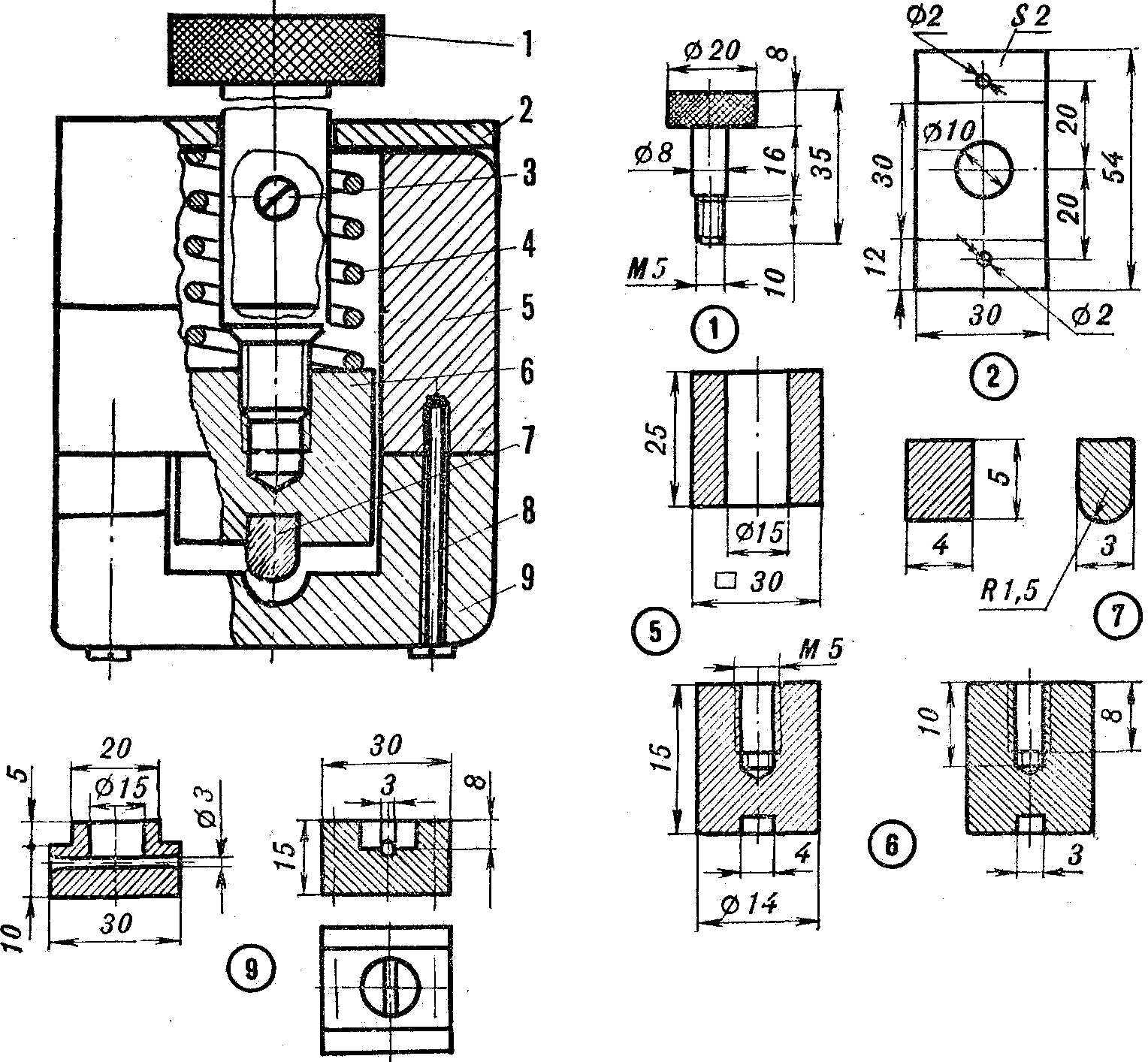
Fig. 4. The stacking mechanism and its details:
1 — adjusting screw 2 — spring retainer 3 — M3 screw, 4 — spring, 5 — body, 6 — clamp, 7 — dry 8 — screw, 9 — base mechanism.
Bobbin with wire is set on the axis passed through the lateral body wall (figure — left) and two internal partitions. The falling axis prevents lock — 2-shaped steel catch.
The front middle panel of the machine has a groove width of 20 mm, which length can freely slide to the stacking mechanism (the design and details in figure 5). Its task is to provide uniform tension in the wire and gently turn to turn to lay it on the frame.
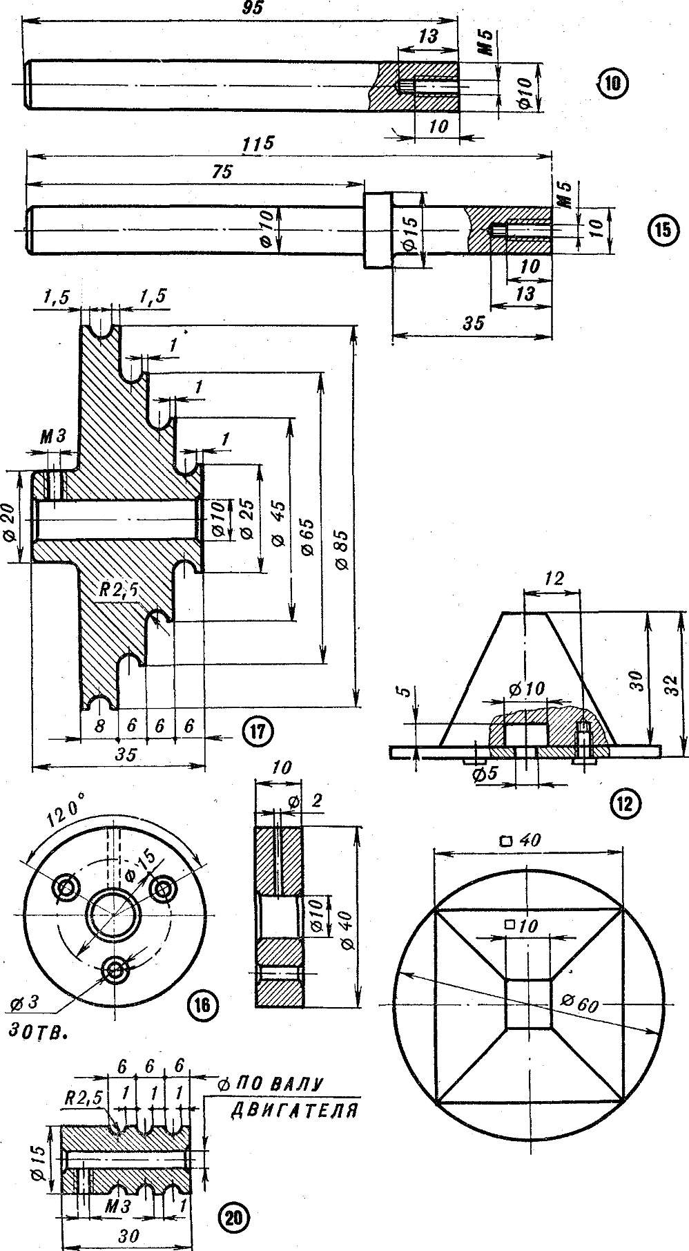
Fig. 5. Some of the details of the semiautomatic machine (part numbers correspond to the positions of figure 3).
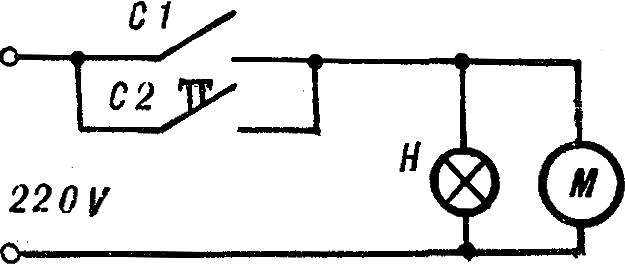
Fig. 6. Wiring the machine.
Now, when the machining is already done, try to wind the first coil. First, you need to fix on the axis of a bobbin with wire, and between the pyramids to insert the frame of the transformer. The end of the wire is passed through the stacking mechanism and is fixed on the frame. Set the adjusting screw of the required tension of the wire, record the number on the meter display (zero reference point) — the machine is ready to work.
Turn on the motor — your function will be only uniform movement in a groove stacking mechanism and observe the meter display.
According to the magazine “ABC tehnike”, Yugoslavia
Recommend to read
 COUNTRY, PORTABLE
With the approach of the summer season this bed is disassembled and can be transported to your countryside area even on the train or commuter bus: its components are easily disassembled...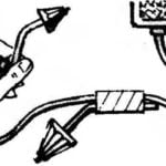 THE KEY IS IN THE IGNITION
When working with a power drill often lost the key to her patron. He will always be on hand if you tape it with electrical tape to the cord at a distance of 0.5...0.6 m from the arm. ...
