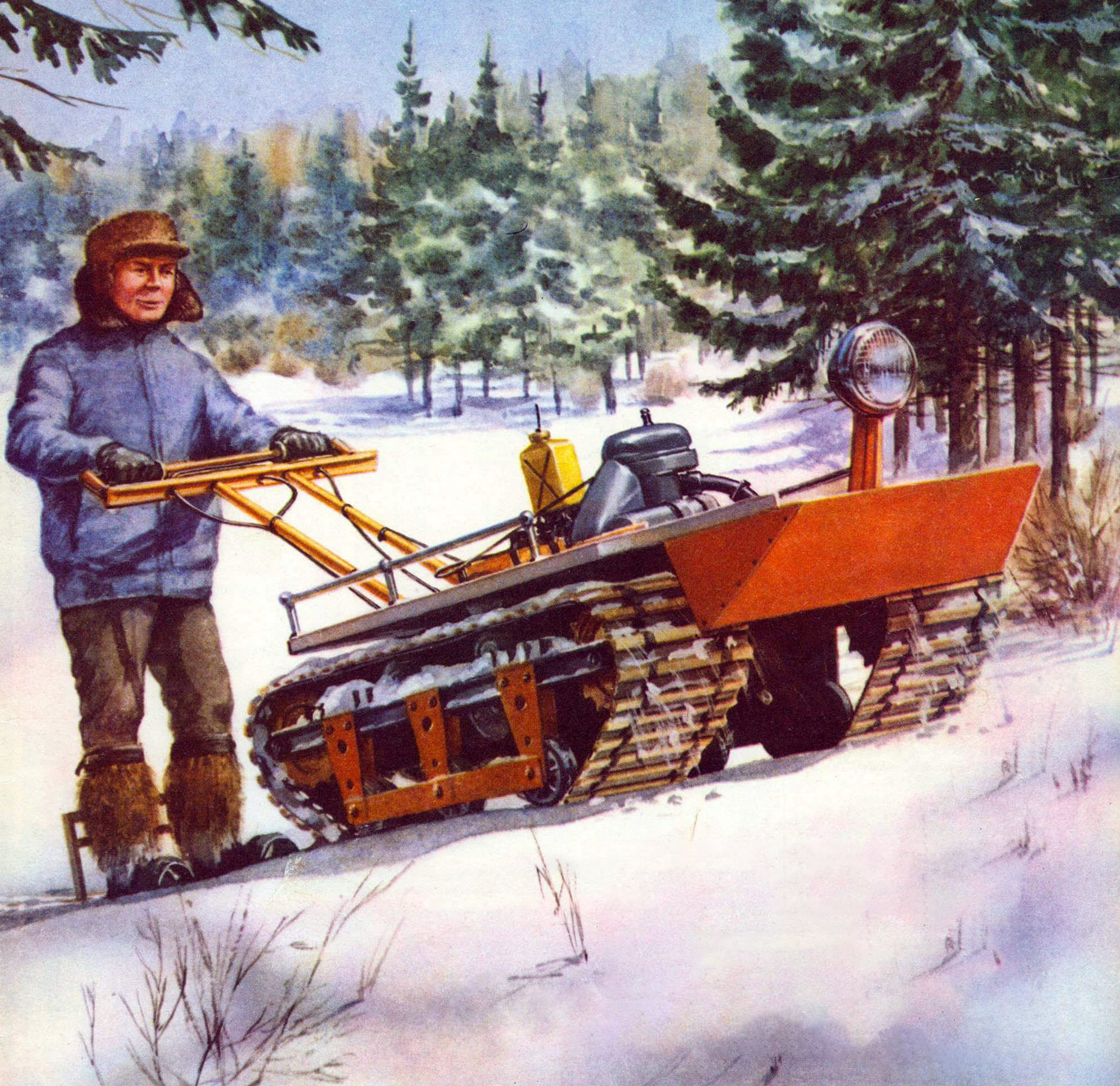
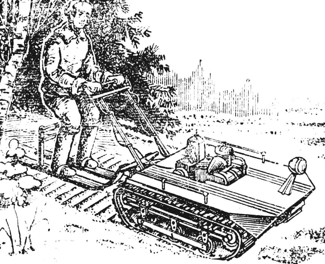
In the snowmobile “Blizzard,” which I designed based on many developments published in “M-K,” elements of the schemes of classic snowmobiles, “amfitrak,” snowcat, pneumatic sleds, and aero skis have come together, combining almost all known snowmobile mechanisms. However, my vehicle cannot be attributed to any of these groups – it is a combination of a tracked drive and skis on which the driver stands. That’s why I called my snowmobile “motoski”. Riding them really feels like a regular ski trip because the driver stands while controlling the snowmobile.
Experience has shown that the scheme has several advantages: high maneuverability and good cross-country ability at a satisfactory speed – up to 15-25 km/h.
Snowmobile consist of two main elements: a motor unit with a tracked drive and skis directly connected to the motor unit with a universal joint. Drive control is carried out using an extended handlebar and throttle, clutch, and variator control levers. To better track the surface when moving uphill, the skis are connected by a parallelogram. This scheme, combined with the universal joint, provides greater flexibility for the running gear, which is especially important when moving over uneven terrain.
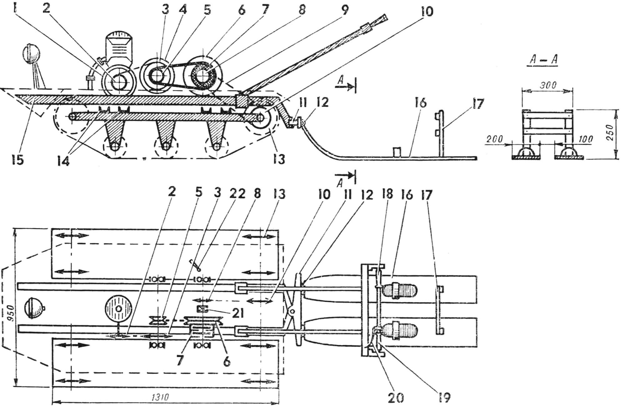
1 – engine starting pulley, 2 – sprocket Z=15, 3 – sprocket Z = 30, 4 – variator pulley Ø 180 mm, 5 – variator pulley Ø 100 mm, 6 – variator pulley Ø 230 mm, 7 – dry double-disc clutch, 8 – sprocket Z – 15, 9 – drive chain, 10 – side sprocket Z = 45, 11 – towing rocker, 12 – ski mounting joint, 13 – track sprockets Z = 12, 14 – cross beams, 15 – sub-motor beam, 16 – ski, 17 – parallelogram, 18 – throttle control handle, 19 – variator control handle, 20 – clutch control handle, 21 – reverse mechanism, 22 – clutch lever.
Motor unit frame – four main beams, four welded cross members attached to them, and two more beams serving as the sub-motor frame. A buffer guard is attached to the front of the latter at a 35° angle, and loops for suspending the towing rocker are attached to the rear. All beams made of 2 mm steel have a channel section measuring 45X30 mm. Thin-walled tubes with a diameter of 35—40 mm can also be used. The ends of the main beams are equipped with cup end caps for track tensioning. Regulating holes are made in the welded tail sections (three in the front, two in the rear). Bearing housings No. 203, closed with nuts, are pressed into the cups.
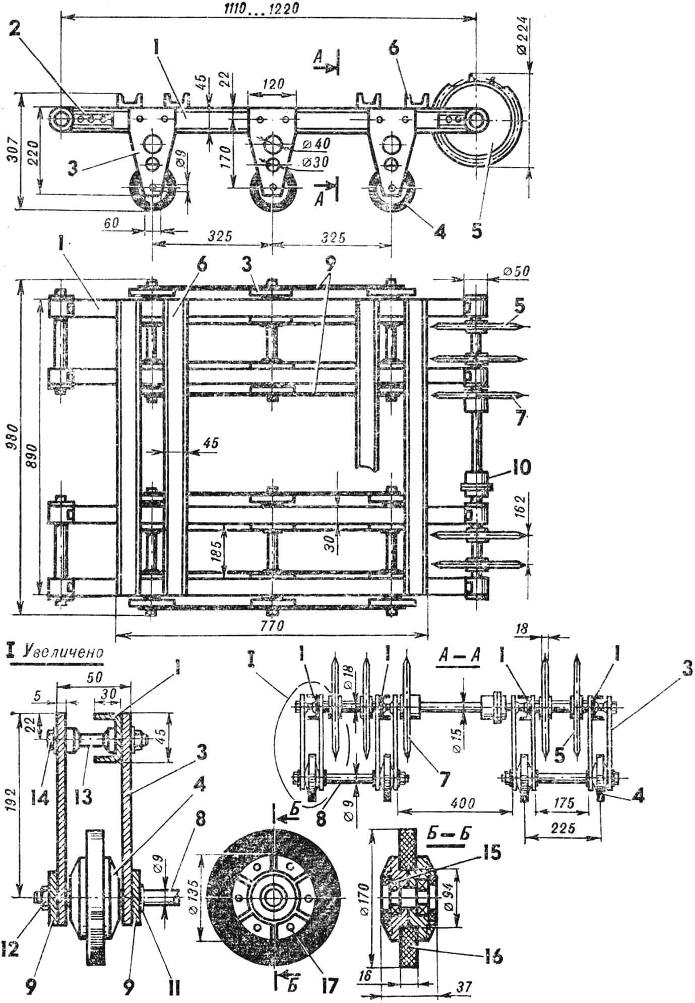
1 – main beam, 2 – cup end cap, 3 – roller support post, 4 – roller support, 5 – track drive sprocket, 6 – cross beam, 7 – drive sprocket, 8 – roller axle, 9 – pad, 10 – coupling, 11 – washer (welded to the pad 9), 12 – nut M8, 13 – thrust roller, 14 – clamping bolt M8X60, 15 – bearing No. 29, 16 – rubber tire of the roller, 17 – hole for the clamping bolt M6X40. Cross beams are not shown on the section A-A.
Three support posts are bolted to each main beam, with one roller installed in each post. To reduce the weight of the posts, they are lightened by drilling. The roller hubs consist of two halves made of AL-2 alloy and are fastened with clamping bolts. The rollers have a rubber tire and are connected in pairs by axles. Longitudinal pads are put on the axles, connecting three pairs of roller supports and providing the necessary rigidity to the entire drive mechanism.
Track – a conveyor belt 7 mm thick, 300 mm wide, and unfolded length of 2900 mm. Fifty-eight bars are riveted to it with a 50 mm pitch.

1 — main beam (45×30 channel), 2 — cup tail (41X25 channel), 3 — cup body, 4 — sprocket shaft, 5 — thrust washer (nut M42), 6 — nut M16X1.5, 7 — bolt for attaching the tail M8X20, 8, 9, 11 — thrust bushings, 10 — bearing No. 203.
The track is driven by two pairs of rear sprockets connected by an intermediate shaft. Both drive and tension sprockets are identical and made of 18 mm thick textolite (Z = 12). On the intermediate shaft, there is a side sprocket (Z = 45) to which the torque is transmitted from the engine through a chain drive. Both drives rotate synchronously; the turning of the motoskis is achieved by changing the direction of the entire snowmobile.
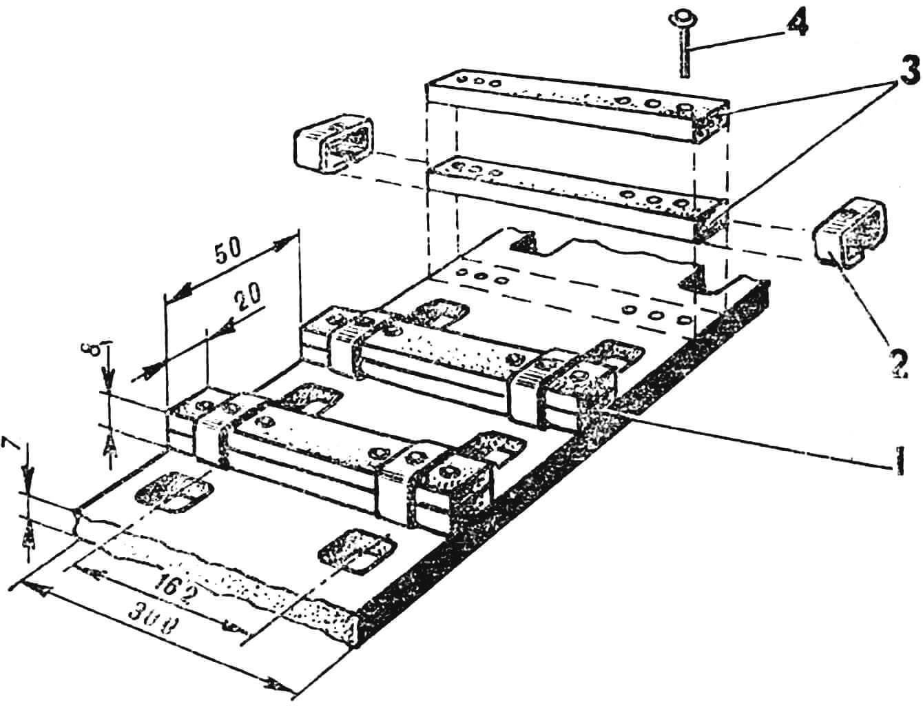
1 — rail assembly, 2 — bracket, 3 — rubber strips, 4 — rivet.
Now about the power unit. Many enthusiasts use the PD-10 starter with an Izhevsk cylinder. I was able to create a similar combination but with a PD-8 engine and a cylinder from a Tula motor scooter. The PD-8 has small scavenging windows, so by replacing its cylinder with a cylinder from the T-200 or “Tulitsa” motor scooter, the engine power increases from 8 to 10—12 hp. Since the PD-8 cylinder head is designed for a large combustion chamber volume, to maintain the same compression ratio as on the T-200, I had to use a motor scooter cylinder head. In addition, the projections of the former gearbox were trimmed from the PD-8 crankcase. As a result, a simple and reliable engine was obtained. The engine is started with a cord, for which a pulley is installed on the left crankshaft journal.
The most important element of the motorski transmission is the variator, combined with a dry two-disc clutch, which I made according to my own calculations. However, I cannot recommend replicating it in the same design. The variator was designed for a specific belt that I had. I think its design and some parameters (especially the adjustment range) can be improved. The only advice I can give to enthusiasts: if the belt is relatively narrow, milling the pulley discs can be useful to increase the adjustment range, allowing the halves of the pulley to enter each other (on motoskis, this mutual entry is 10—15 mm). Enthusiasts of technical creativity from Khanty-Mansiysk V. Meledin, A. Abdurashitov, and V. Kurdenko used a similar method (see “M-K” No. 1 for 1978). I also won’t provide drawings of the motoski reverse mechanism because all five of its gears are homemade, and there is hardly any sense in replicating them one-to-one.
During operation, it turned out that a significant part of the power is consumed by the rotation of the drive. Therefore, it is advisable to reduce the thickness of the track belt to 4—5 mm to give it greater elasticity. There are also reserves in lightening the construction: many of its power elements can be made from lighter materials. To reduce the specific ground pressure, it is useful to increase the width of the tracks. So, I have plans to significantly improve my “Blizzard” in the future.
N. Skrebnev
Recommend to read
 SKILLFUL IMITATION
Sometimes at sea the second tier questions the defense put unsoluble problems, missing that great powers have just in principle. So, Spain, its naval policy dictated not by economic... ASSAULT TANKS OF THE WEHRMACHT
Classification of self-propelled artillery of the Wehrmacht were quite complex and confusing. There were several main classes of ACS: Sturmgeschütze — assault guns, Selbstfahrlafetten —...
