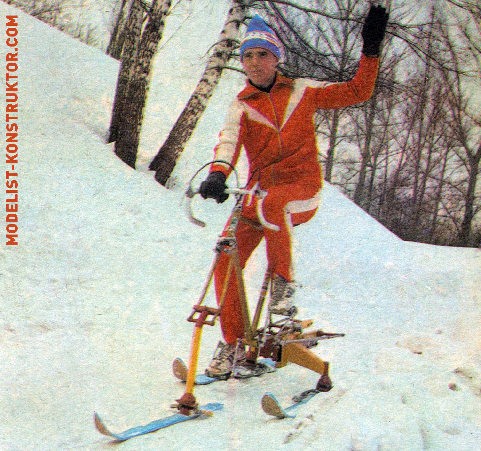
Attempts to combine a bicycle with skis have been made before. However, the resulting snowcat designs could only be used to ride down hills. Our reader and engineer L. Gurfinsky, along with his friends, managed to construct a simple reciprocating mechanism that transforms the snowcat into a ski-bicycle: now it can be ridden both downhill and uphill, as well as on flat terrain.
Simply replace the rear wheel with a guiding frame, attach a paired ski drive to it, and replace the front wheel with a steering ski — and you’re ready for a ride!
When winter arrives, most cyclists are forced to store their bikes away. Snow and ice make bicycles unsuitable for riding: their narrow tires are not well-suited for winter conditions — unlike skis. But why not replace the wheels with skis? Then the pedal-powered machine could be used year-round.
Such a design has been created and patented with Certificate No. 971374. Its distinctive feature is reflected in the name itself: Ski-Bicycle. With it, you can not only ride down hills but also take leisurely walks on snowy trails following skiers.
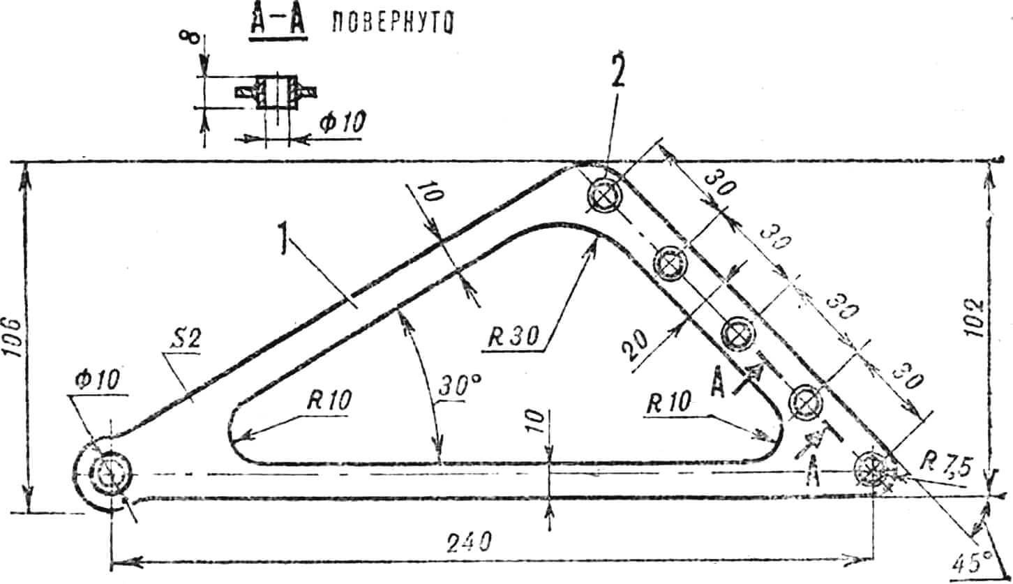
The Ski-Bicycle, shown in the general view on the tab and in figure 1, is manufactured based on a standard bicycle. Its main components include the frame, front and rear supports, brackets, front steering ski, and rear supporting ski-pushers.
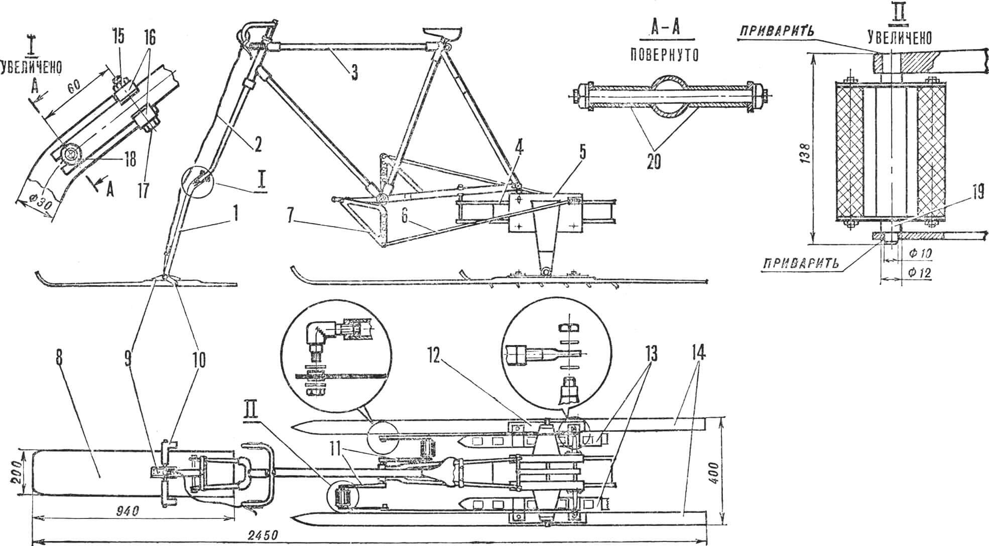
1 — front support, 2 — brake cable, 3 — frame, 4 — bracket, 5 — rear support, 6 — rod, 7 — lever, 8 — front ski, 9 — front overlay, 10 — brake, 11 — crank, 12 — rear overlay, 13 — ski-pushers, 14 — rear skis, 15 — nut, 16 — plate, 17 — bolt, 18 — axis, 19 — pedal axis, 20 — spacer hubs.
The frame is from the “Start-road” sports bike; only the crank assembly has been replaced. Frames from road bikes or children’s bikes like “Orlenok” can also be suitable, with adjustments made to the specified dimensions.
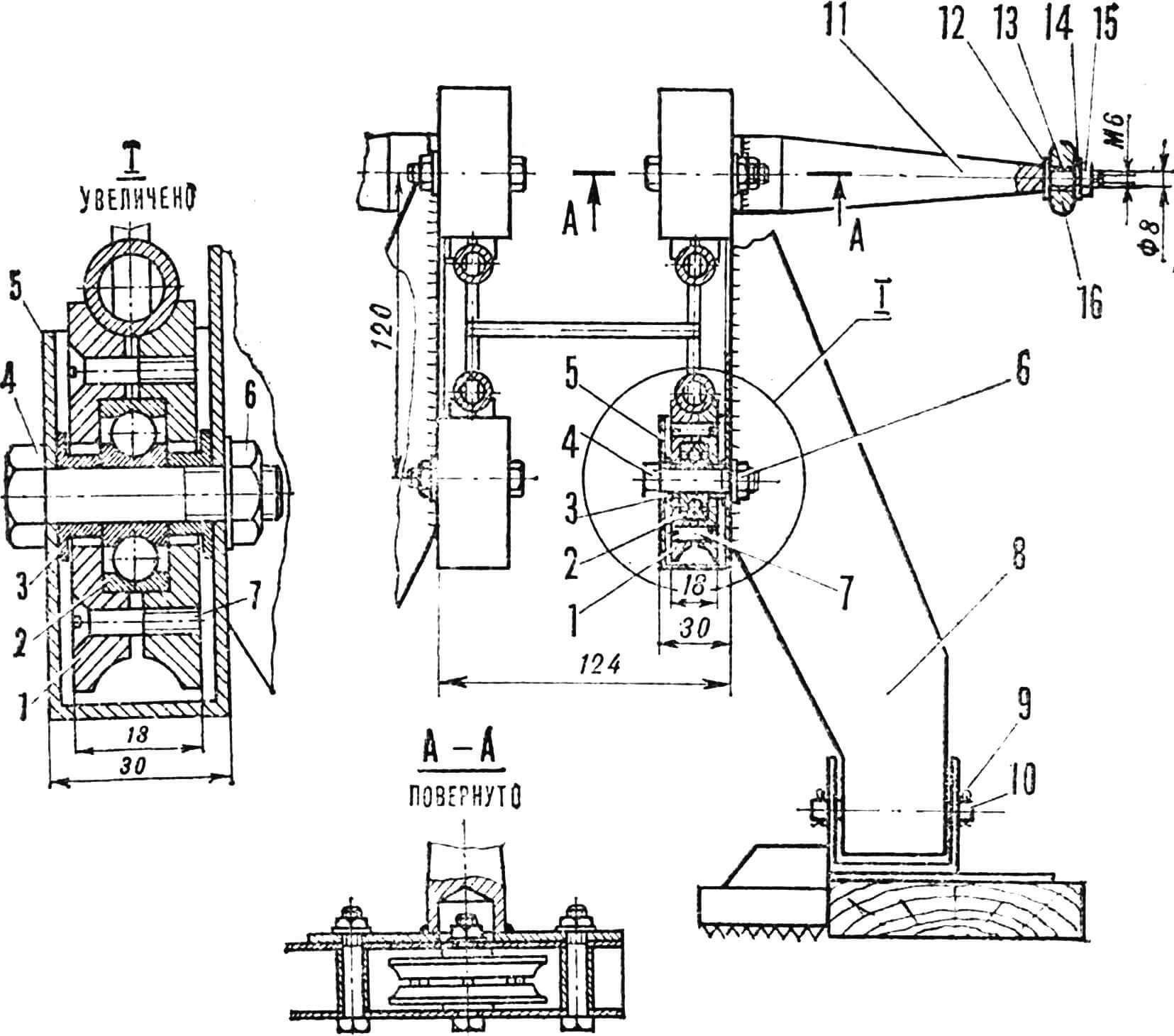
The replacement of the crank assembly involves installing cranks with extended pedal axes instead of the usual ones. Ski-pusher levers are attached to these axes. Standard parts for the new cranks can be purchased at stores or spare parts departments, or salvaged from a retired bicycle. The threads in the pedal holes of the cranks are worn out, so steel rods with a diameter of 18 mm are inserted and welded into them. After installing the pedals, the levers are also installed and welded. They should be oriented so that the lines along which the holes are located are perpendicular to the cranks and pass through their axis of rotation. This orientation facilitates the most rational distribution of forces during riding. The material for the ski-pusher levers is a 4 mm thick steel sheet, and the embedded bushings can be cut from a suitable pipe.
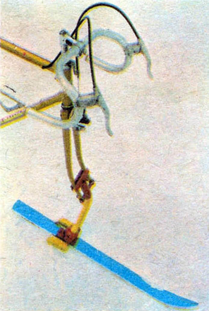
The front support of the Ski-Bicycle, which is an arched metal tube with a diameter of 30 mm, is attached to the steering fork in two places. The main load is on the axis — a steel rod with M8 threads cut at its ends. Two spacer hubs made of metal tubing secure the support in the middle of the fork. To prevent lateral shifts, the ends of the fork-clamping plates, made of 2 mm thick metal sheet, are bent.
The front support is attached to the ski on an axis made of Ø 8 mm steel rod, with Ø 1.5 mm holes drilled for cotter pins at both ends. The axis passes through holes in the support, overlay, and brake. The overlay is made of 2 mm thick metal sheet and is fastened to the ski with six screws.
1 — roller, 2 — bearing, 3 — spacer hub, 4 — bolt, 5 — box, 6 — nut, 7 — screw, 8 — support, 9 — cotter pin, 10 — axis, 11 — bracket, 12 — washer, 13 — PTFE bushing, 14 — washer, 15 — nut, 16 — adjustment bolt of the rod.
The brake consists of two elements, having a G-shaped cross-section, located on both sides of the overlay. A lever and the rear wheel brake cable are used to actuate the brake. The cable, with its housing, presses against a bracket secured by two M3 screws on the front support.
To enable the Ski-Bicycle to ride not only on packed snow but also on fresh powder, the specific pressure exerted on the snow should not exceed 16 g/cm². Based on this value and the maximum weight of the rider, the support area is calculated. Due to the frame’s design, both the front and rear skis bear equal loads. Thus, the support area of the front ski of a Ski-Bicycle intended for powder should equal that of the rear skis.
The front ski is made of wood, manufactured using a technique described in “Modelist-Konstruktor.” To improve glide, plastic is glued to the lower surface with epoxy resin.
Wood is not the only material for skis. A metal sheet, 2 mm thick, such as aluminum alloy, can also be used. In this case, stiffness ribs, such as angles installed with rivets, should be provided.
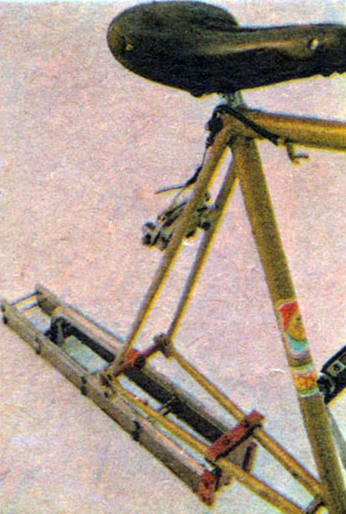
The construction of the Ski-Bicycle’s bracket is understood from the diagram. Its guides are made of Ø 16 mm metal tubing bent in a P shape. The bracing material is Ø 4–5 mm steel rod. Horizontal crossbars of the same rod are welded to the braces, preventing deformation of the guides under bending forces. Dowel pins are machined from Ø 10 mm steel rod. Plates are made of 5–7 mm thick metal sheet, with inclined recesses where the lower fork tubes of the bicycle frame are clamped.
The bracket console is made of metal tubing. The console is installed on two Ø 8 mm steel rod braces welded to the braces. An axis hole is drilled in the upper part of the console, made and installed the same way as on the front support.
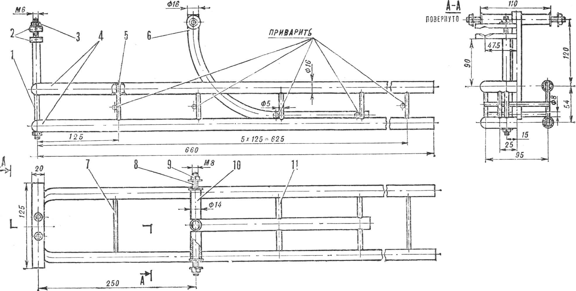
1 — dowel pin, 2 — plates, 3 — nut, 4 — guides, 5 — brace, 6 — console, 7 — crossbar, 8 — axis, 9 — nut, 10 — spacer bushing, 11 — crossbar.
The boxes of the rear support are made of 2 mm thick metal sheet. Their main dimensions are 280x185x30 mm. Each box accommodates four rollers, each consisting of two halves joined with M6 screws. The rollers are installed on № 200 bearings. Spacer hubs, machined from Ø 18 mm steel rod, prevent the roller bearings from shifting laterally. The rollers can be made of steel, aluminum alloy, or bronze.
To eliminate the possibility of the upper rollers coming off the guides, it is necessary to provide for their height adjustment. Oval-shaped holes for the upper bolts are better to avoid this issue.
The brackets of the rear support are attached to the boxes with M6 bolts. To prevent deformation of the box walls when tightening the nuts, it is advisable to insert bushings cut from metal tubing. The brackets are machined from Ø 30 mm rod; plates with a thickness of 2–3 mm are welded to them, and bolts are inserted into the holes.
The post of the rear support, a welded structure, is made from 2 mm thick metal sheet. Welding is the preferred method for attaching the post to the box. However, threaded connection using four M6 bolts can also be used.
The axes, like those on the front support, are made from Ø 8 mm steel rod with holes for cotter pins.
The material for the overlays of the rear skis is a 2 mm thick metal sheet. Twelve Ø 3 mm holes and two Ø 8.5 mm holes are drilled in them, with the countersinks of the latter enlarged from the bottom. The smaller diameter holes are for screws used to attach the overlays to the skis, and the larger ones are for M8 screws with concealed heads. After welding the heads of the M8 screws, the welded seams are cleaned.
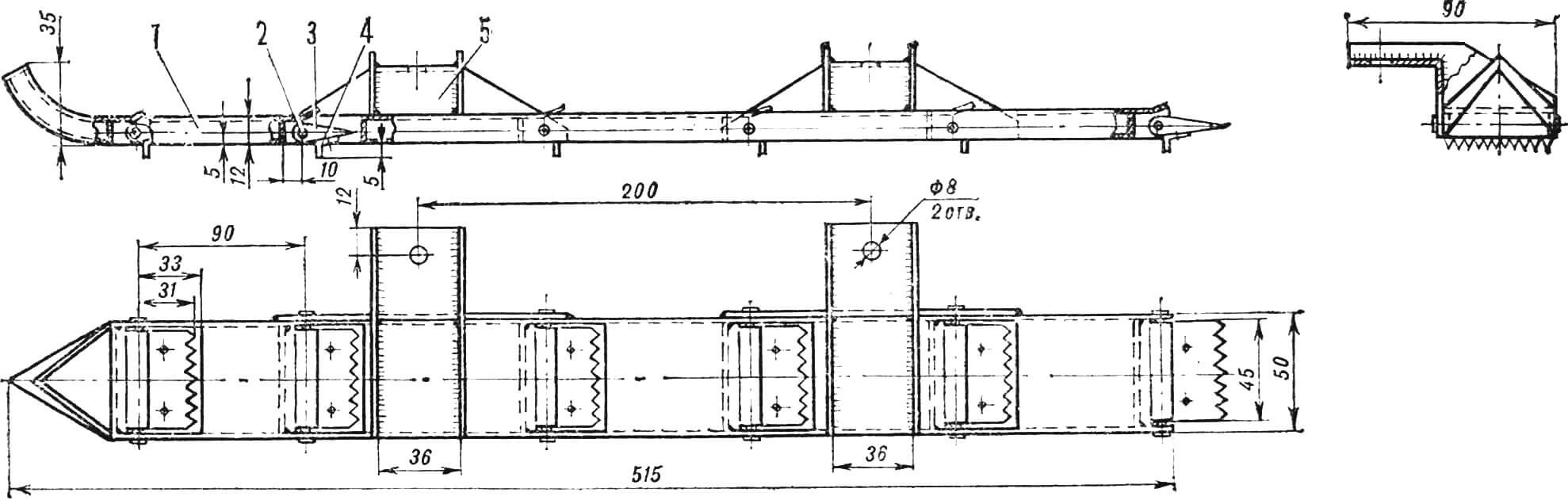
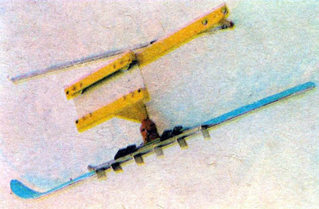
1 — ski, 2 — axis, 3 — ground cleat, 4 — comb, 5 — bracket.
The ski-pusher (Fig. 5) is made of sheet metal with a thickness of 1–2 mm in the form of a box with a sharpened and upward-bent front part. All elements of the ski are connected by welding. Windows are cut out on its upper and lower surfaces. The upper windows have stops for limiting the rotation of the ground cleats. The ground cleats are made of 10 mm thick metal plates. They are pivotally installed on the ski, and their axes are Ø 4 mm steel rods with holes Ø 2 mm and a depth of 3 mm drilled on their ends. After installation on the ski, they are riveted.
The combs, made of 2–3 mm thick metal sheet, are attached to the ground cleats with M3 screws. Triangular-shaped teeth are cut out on both the ground cleats and the combs. The angle between the forming edges of the teeth is 60°. The height of the teeth for the ground cleats is 6 mm, and for the combs, it is 4 mm.
The ski-pusher is connected to the supporting ski with brackets attached to the overlay using M8 screws. The sliding plane of the supporting ski should be 5 mm lower.
Standard “Forest” skis are used as the supporting rear skis; they are only slightly shortened.
In an ideal case, the functions of the pusher and the disputable ski should be performed by a single element. Such a design can be recommended, for example, for a children’s version of the ski-bike.
1 — lever, 2 — bushing.
To make the rod that connects the lever to the bracket of the rear support, a Ø 16 mm metal tube with a length of 600 mm is used. Round M8 nuts with a flange are installed on its ends. They can be machined from a Ø 15–16 mm rod. To prevent rotations and axial shifts, it is better to fix the nuts with welding.
The rod is connected to the lever with a G-shaped bolt, bent from a Ø 10 mm steel rod; the bending point is welded (before bending the rod, cut a recess at the bending point with a round file). The part of the bolt that enters the bushing on the lever is processed similarly to the end of the bracket of the rear support. Threads M8 are cut on the other end.
The rod is connected to the bracket with an adjusting bolt M8; its hole is enlarged to Ø 10 mm. If there is no standard bolt at hand, make it yourself by welding a stud or set screw to a washer.
The riding technique on the ski-bike does not differ from cycling. Moreover, since it is more stable than a bicycle, learning to control it is much easier.
When pedaling, the rear supports with skis, moving on rollers along the brackets, make reciprocating movements. When the ski-pusher starts sliding backward, the combs catch onto the road surface, and the ground cleats, coming out of the lower windows, dig into the snow. Sliding stops, and the ski-bike takes a step. Its length corresponds to the diameter of the circle described by the bushing into which the G-shaped bolt is inserted. When sliding forward, the ground cleats hide in the ski-pusher. Snow sticking to them is thrown out through the upper windows. Limiters prevent the ground cleats from getting stuck.
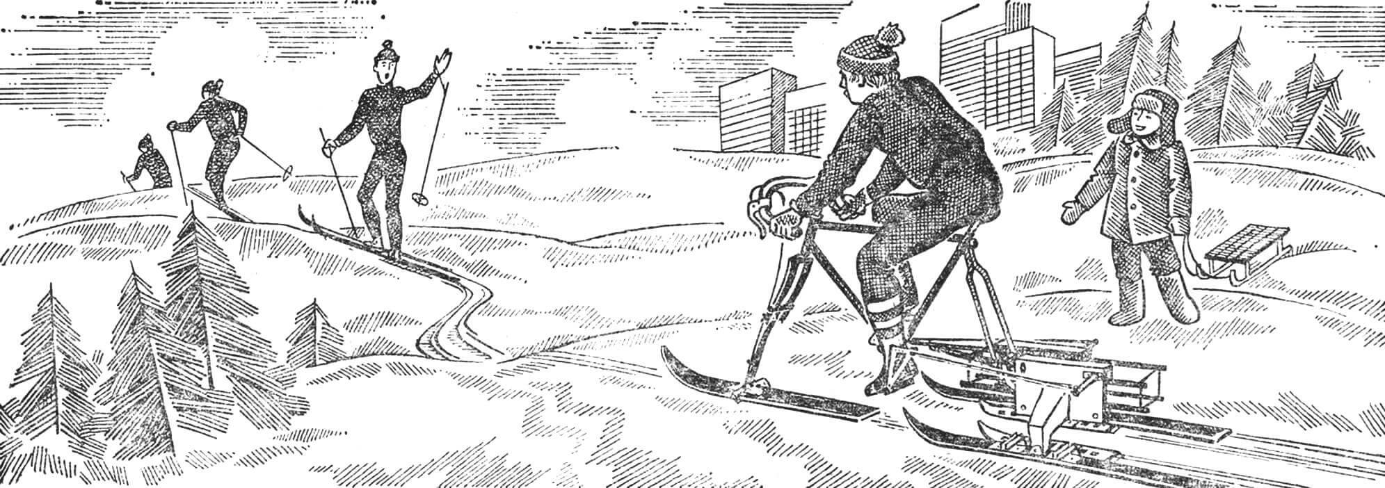
Even an untrained person can easily reach a speed of 8–10 km/h on the ski-bike. Of course, for a trained athlete, this is not the limit. If someone finds it difficult to pedal, the step can be shortened. However, after that, the speed will decrease, but the efforts expended will also decrease.
The maneuverability of the ski-bike is not high: the turning radius is 2 m. Therefore, it is better to ride it on relatively flat and straight tracks laid along frozen riverbeds, canals, or clearings.
Every appearance of the ski-bike arouses inevitable interest. People approach, ask about the design, and inquire about the capabilities of the machine. Many are inspired by the idea of building a similar snowmobile for themselves or their children. We hope that this publication will help them independently manufacture a ski-bike.
L. GURFINSKY, A. KOROTKOV
Recommend to read
 WASHER AGAINST SCRATCH
Means and ways to curb the creaking doors invented a lot, but almost all of them require regular renewal of any grease. Meanwhile, there is a kind of "lubricant" that will work... FROM VELCRO — BRUSH
Clasp type "burdock", which is widely used on jackets and other apparel, consists of a strip with a loop surface and pressed against her other band with a dense network of small hooks....
