 If you try to list all the known constructive scheme of ATVs, that’s probably not enough of this page — after all, their number comparable to the number of Amateurs involved in all-terrain equipment. In this list you will find the place and motonarty, and snowmobiles, and apparatus on the air cushion… And as it turns out, it is harmless to look back and see whether all the “care” of the oldest known structures? Did a reader of our magazine A. Kremnev, designing all-terrain vehicle-amphibious “Ob”.
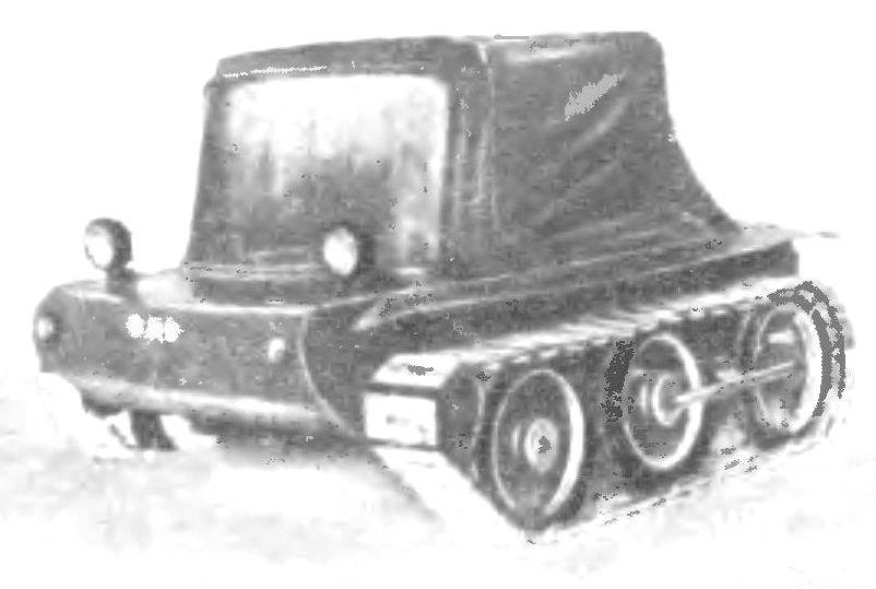
In our panorama (see “M-K” No. 2, 1977) was a photograph of this machine and a little information about it — just a few lines of description. The publication caused a lively reader’s interest, as evidenced by several letters received by the editorial Board and all unanimous request: send drawings! Revision requested A. Kremneva to prepare more detailed material on my ATV. The answer was not long in coming — he’s in front of you!
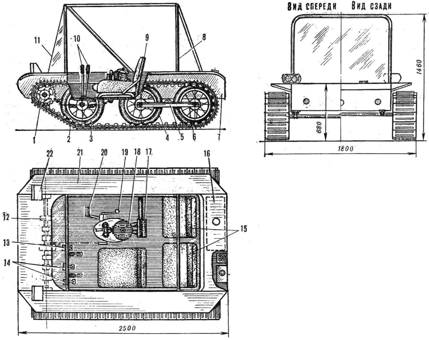
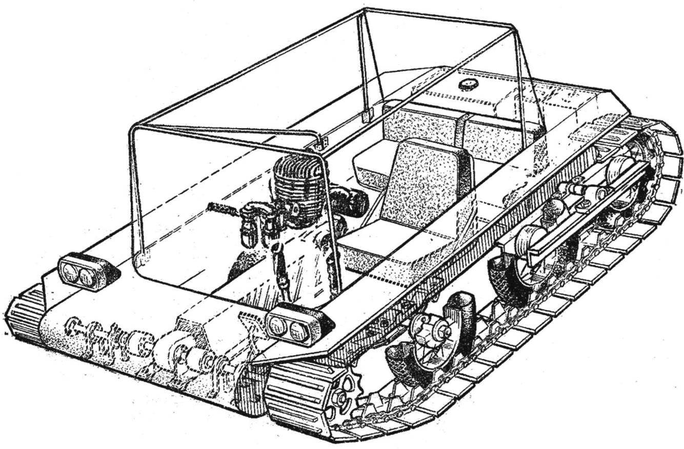
The main advantages of the “Ob” (Fig. 1) simplicity and functionality. Everything — from the body to chassis.
Fig. 1. The layout of the Rover “Ob”:
1 — drive sprocket, 2 — caterpillar mover, 3, 4, 6 — rollers, 5 — carriage rear rollers, 7 — casing, 8 — the tubular frame tent, 9 — driver seat, 10 — levers clutch, 11 — windscreen, 12 — main gear, 13 — clutch pedal, 14 pedals brake, 15 — seat passengers, 16 — fuel tank, 17 — muffler 18 — engine, 19 — shift lever 20 — pedal kick, the 21 — mudguard, 22 — Farah.
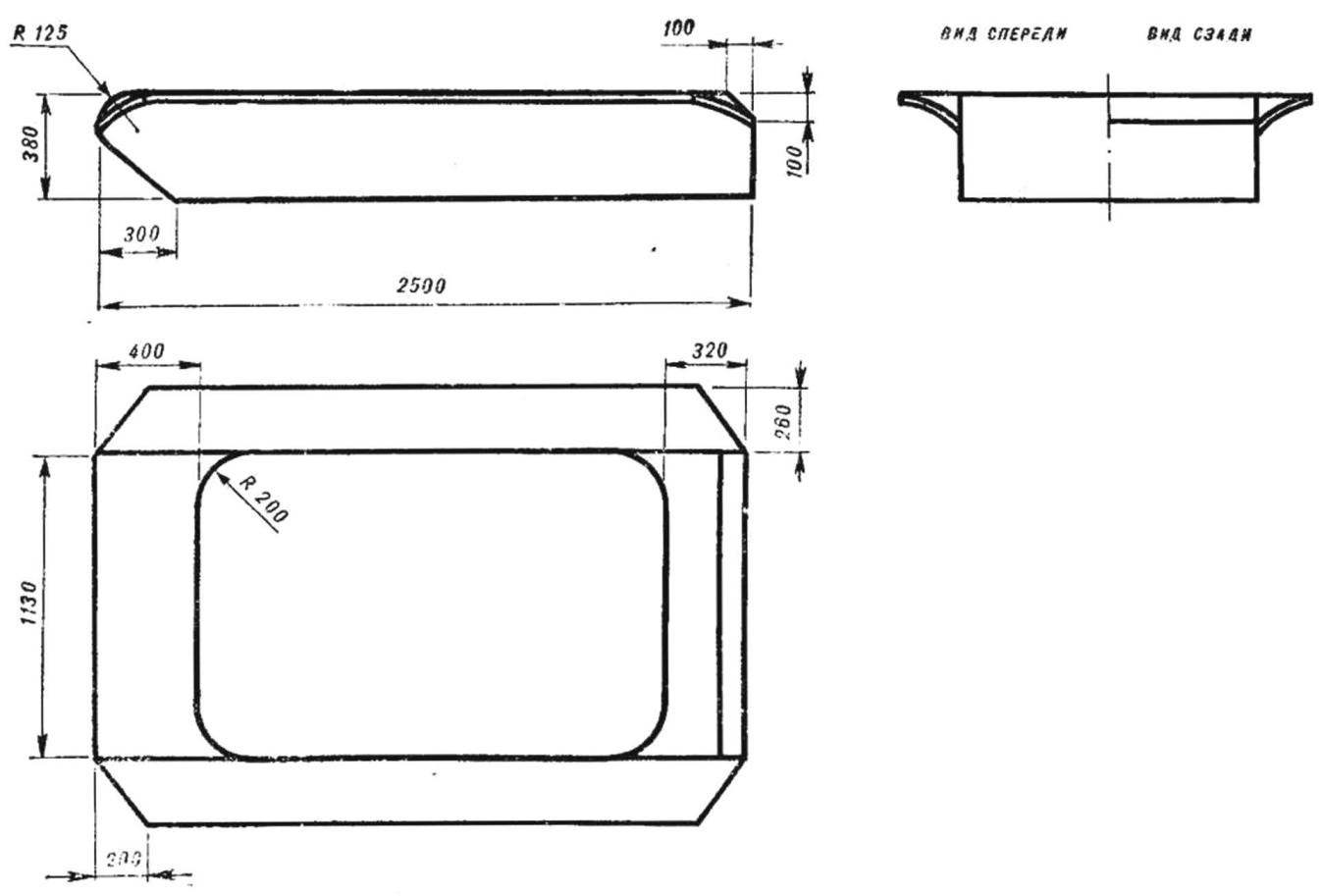
Fig. 2. The body of the Rover.
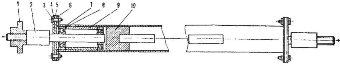
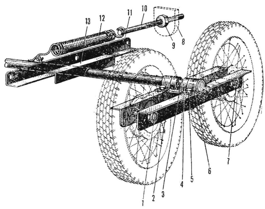
Fig. 3. Front axle:
1 — notched nut, 2 — axis, 3 — bolt M6 nut 4 — bearing cover, 5 — leather cuff, 6 — flange, 7 — beam front axle, 8 — bearings No. 205, 9 — spacer, 10 — wooden plug.
Fig. 4. Installation diagram for the front axle:
1 — bolt M8 with nut, 2 — plate, 3 — the case of Rover, 4 — bolt M8 with nut and washer, 5 — plate 6 — bracket 7 — semi-elliptic leaf spring, 8 — ladder 9 — front axle 10 — front bracket, 11 — axis.
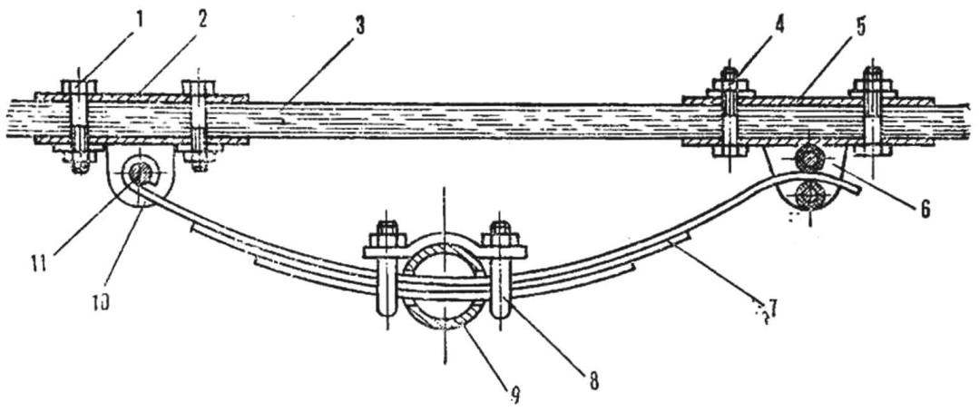
Fig. 5. Carriage rear rollers:
1, 7 — axis rollers, 2 — rocking chair 3 — axis carriage, 4 — restrictive sleeve, 5 — bolt M8 with nut and washer, 6 — bolt, 8 — base plate bracket 9 — nut tensioning device, 10 — rod, 11 — slide, 12 — spring, 13 — slide.
What is this vehicle amphibious? To begin the description it follows, apparently, from the housing (Fig. 2). It is made from sheets of plywood 12 mm thick, connected by a metal profiles (area) and rivets. Stiffness and strength were such, that there is no need to frame. Therefore, the unibody amphibians turned weighing only about 45 lbs.
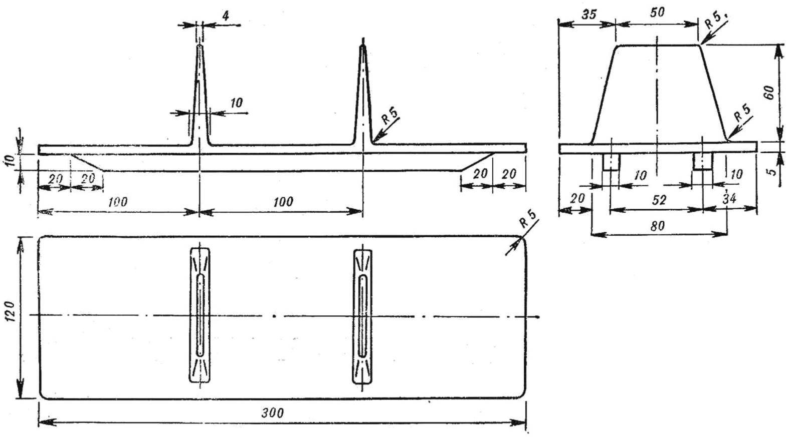
It was not easy to solve the problem of caterpillars — a common, perhaps for all homebrew. Aluminum trucks, cast in a makeshift foundry, and riveted to roller chain, the mover of my Obi. Each caterpillar weighs about 38 kg. the Principal dimensions of the trucks is shown in figure 6. Caterpillar mounted on six rollers — the wheels of a motorcycle “rising” and are driven by four sprockets, two on each. Rollers mounted on three axles on ball bearings.
Front axle (Fig. 3 and 4) mounted on two longitudinal semi-elliptic leaf springs, each of which is recruited from three plates. Rear axle rollers are suspended on a moving (swinging) the frame assembled from steel sections (angles). Adjusting track tensioning, as in most such designs is longitudinal movement of the frame (Fig. 5).
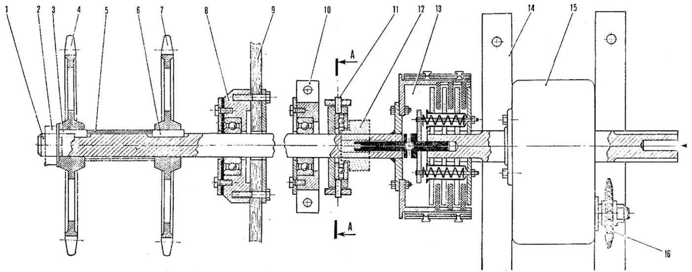
Leading asterisks are placed on the axis of the main transmission (Fig. 8), consisting of gear unit, two clutch mechanisms and a number of supporting and intermediate bearings. The asterisk at the input of the reducer with roller chain connected with the sprocket engine of the motorcycle IZH.
In addition to the driver, “Ob” can “take on Board” two more. For protection from the elements provides easy-to canvas tent: it is attached on the arcs, welded steel pipes.
Fig. 6. Truck caterpillar tracks.
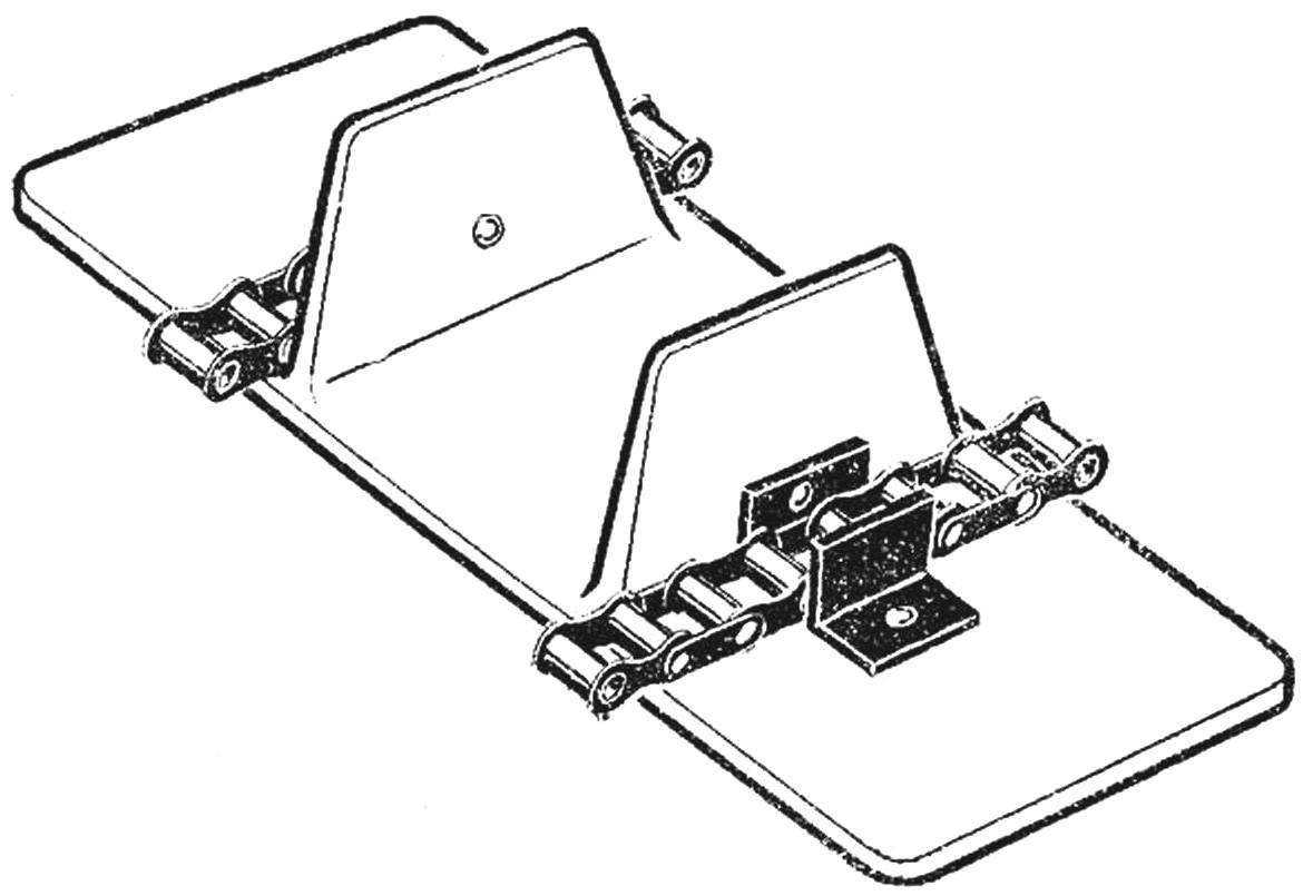
Fig. 7. The design of the caterpillar.
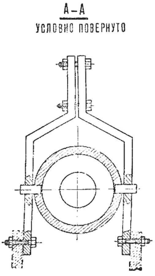
Fig. 8. Diagram of main transmission:
1 — driven shaft, 2 — nut, 3, 6 — pins, 4, 7 — leading stars, 5 — spacer, 8 — bearing No. 206 in the housing, 9 — side panel of the body of the Rover, 10 intermediate bearing No. 206 in the housing, 11 — clamp enable clutch with the thrust bearing 12 is notched dowel, a 13 — steering clutch, 14 — stretcher reducer, 15 — reducer, 16 — sprocket reducer.
To manage the “Ob”. Equipment of a workplace of the driver is a little different from tractor — the same two lever side clutch, clutch pedal, brake pedal, kickstarter and throttle of the carburetor of the engine (gas). The engine starts with the kick starter when you pressed the clutch, then turn on the first transmission (friction clutches are included), and the vehicle moves off. Turn is a off the corresponding clutch. Shifting is almost the same as on any other machine.
A small Rover is not terrible neither snow, nor spring thaw; even the water hazard without difficulty overcome “Ob” — sealed body, caterpillar mover with success works and in the water.
“Ob” is in operation here for about four years, and during that time any serious damage was not. The car is fine, delivering me to and from work on almost any terrain — because by profession I am a fisherman.
A. KREMNEV, POS building, Tomsk oblast
Recommend to read
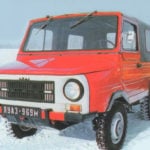 FROM THE “US-1” TO “VOLYN”
Since came to light the car, designers fascinated by the problem of creating a small and cheap machine. Not a toy, a car truly fit for normal use. Early attempts led to the... “DREAM” — A CAR PRESCHOOLER
Dream... How can she be the child? 1949. I am 5 years. Father Andrewski, the boy next door, buy somewhere a used pedal car (our industry at that time, in my opinion, not released),...