First of all, I thank the editorial board of “Modelist-Konstruktor” for promoting the ingenuity, intelligence and talent of ordinary people, for providing the opportunity to use their rich creative experience, concentrated in the magazine. Keep it up!
For my part, I would like to offer readers a description of a very practical mini-truck. Practical in the sense that it is simple in design, easy to operate and inexpensive to maintain. This simple vehicle is designed to transport various cargoes, as well as one passenger. I had long been planning to create such a mini-truck — it is simply necessary in a household. And when a used “Muravey” scooter happened to fall into my hands, I decided to use its main units and parts as the basis for my four-wheeled machine, as more stable than a three-wheeled one. With minor modifications, these units and parts (thanks to the Tula machine builders for the quality of their products!) made it possible to make the design inexpensive to manufacture and reliable in operation.
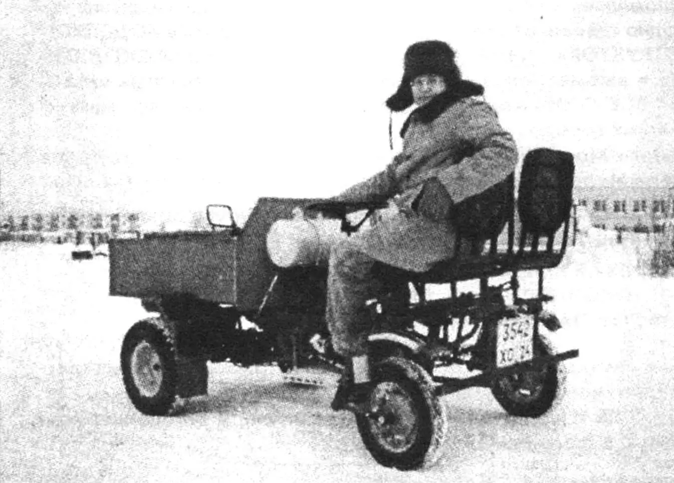
The truck, named “Sledopyt” (Pathfinder), is a “Muravey” redesigned with the body forward. Externally, it somewhat resembles the T-16 self-propelled chassis. But unlike it, it has front drive wheels. The choice of the self-propelled chassis layout is explained by the following consideration: the rear drive wheels of the “Muravey”, becoming the front ones of the truck, increase its cross-country ability, and the front steerable ones, becoming the rear ones, — maneuverability. This gives a certain advantage when driving off-road or in a cramped farmyard.
To realize my idea, I needed to modify the standard front suspensions; manufacture a rear axle beam with bearing units at the ends; adapt a steering wheel from “Moskvich-412”, steering mechanism and ball joints — from “Niva”; install controls for “gas”, clutch, brakes; make seats and a dump body.
All this took four months. The work went smoothly because I was already mentally driving the “Sledopyt”. The finished and painted machine was, as required, registered. True, as… a mini-tractor. This metamorphosis is simply explained: at that time I only had a driver’s license for a tractor. However, this circumstance does not prevent me from using the “Sledopyt” mainly as a vehicle.
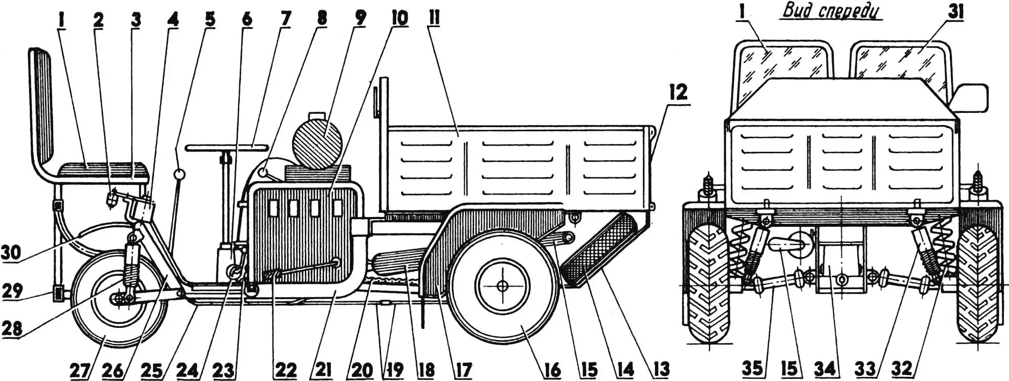
1 — passenger seat; 2 — steering joint; 3 — sub-seat frame; 4 — rear wheel unit, steerable; 5 — gear shift lever; 6 — steering mechanism; 7 — steering wheel; 8 — reverse reducer control lever; 9 — fuel tank; 10 — engine hood; 11 — dump body; 12 — folding side; 13 — protective pan; 14 — spare wheel; 15 — exhaust pipe; 16 — drive wheel; 17 — front fender; 18 — muffler; 19 — brake rod; 20 — chain drive; 21 — mini-truck frame; 22 — kick-starter lever; 23 — brake pedal; 24 — “gas” pedal; 25 — gear shift lever rod; 26 — steering wheel fork; 27 — steerable wheel; 28 — rear shock absorber; 29 — bumper; 30 — rear fender; 31 — driver’s seat; 32 — suspension spring; 33 — front shock absorber; 34 — main drive; 35 — half-shaft with universal joints.
“Sledopyt” is a good helper in a household. In addition, I drive it for mushrooms and berries, as well as for fishing. I operate the truck mainly only in the warm season, so I didn’t make a cab. I sometimes make trips of 100 km and don’t feel particularly tired. The machine is easy to operate — all controls are located right in front of the driver. And although the pedals are spaced a bit wider than on a car, you quickly get used to it.
It’s convenient not only for the driver, but also for the passenger: the machine’s ride is soft, no wonder it has independent suspension on all wheels. Everyone who has ever ridden the “Sledopyt”, sitting in the passenger seat, did not experience, in their opinion, any inconvenience. Later, when the seats got armrests, and above them — a removable awning, the reviews of the trip even included such a definition as “comfortable”.
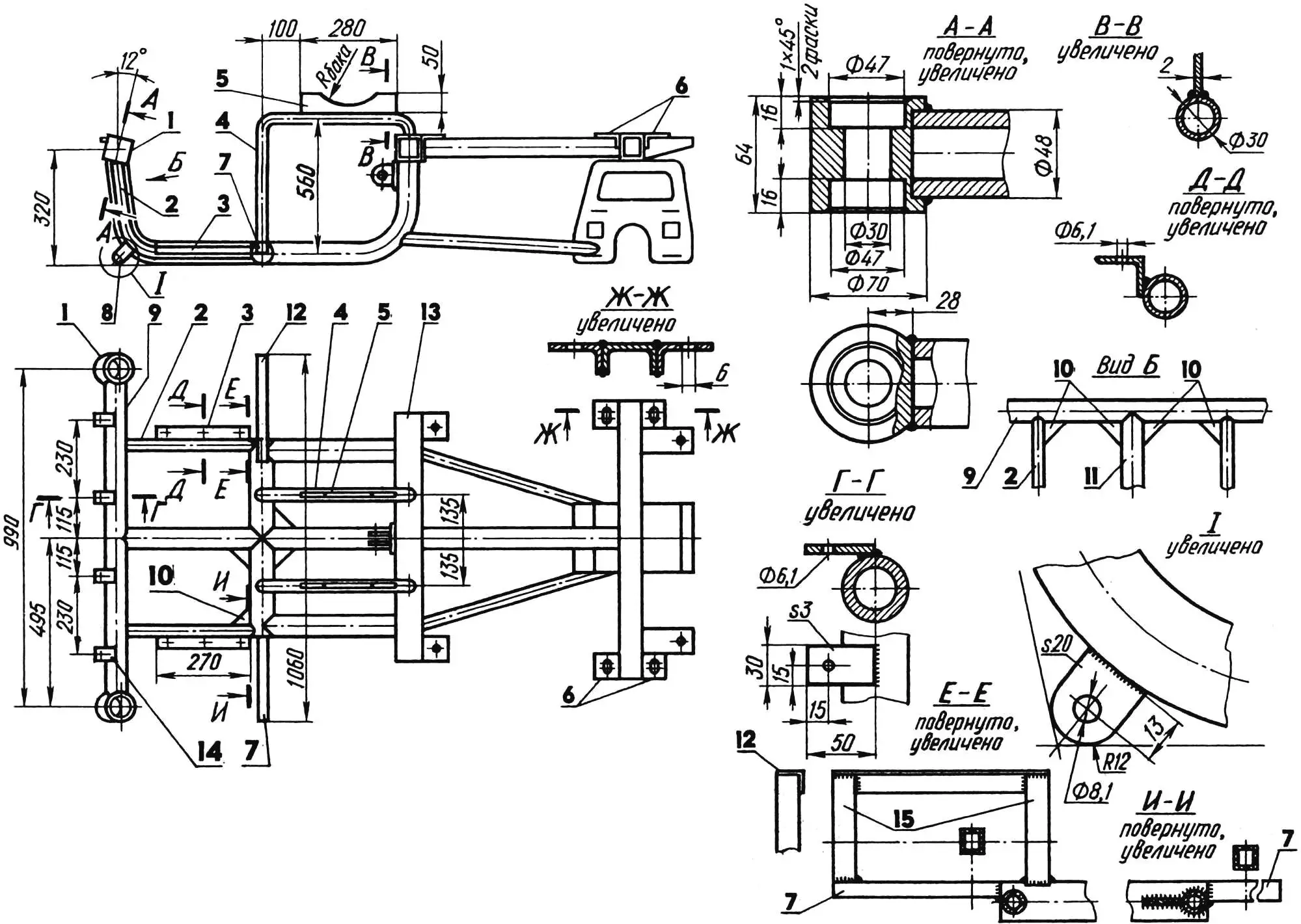
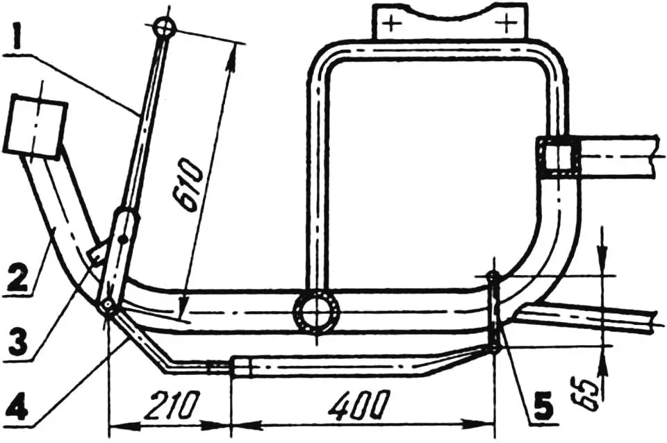
1 — kingpin bushings; 2 — cross members (tube 30×2); 3 — floor mounting brackets (angle 30×30); 4 — former sub-seat frame arcs; 5 — fuel tank cradles (steel, sheet s2); 6 — front fender mounting brackets (angle 70×70); 7 — floor mounting consoles (tube 25x25x2); 8 — sub-seat frame mounting eye (2 pcs.); 9 — rear axle beam (tube 48×5); 10 — gussets (steel, sheet 50×50, s2); 11 — scooter frame knee, central; 12 — clutch pedal mounting bracket (angle 30×30); 13 — scooter frame; 14 — sub-seat frame mounting bracket (4 pcs.); 15 — posts (tube 25x25x2).
In short, I’m satisfied with my mini-truck. I should note its cross-country ability, especially when it’s loaded, because the drive wheels are wide-profile, from the “Tula” motorcycle (steerable ones — from the scooter). It’s just that the power of the “native” engine is not always enough. Therefore, before towing a heavy load, I have to change the motorcycle wheels to scooter ones, and paired ones at that.
The mini-truck body is a dump, swivel type. But it can also be fixed. Then it’s easy to attach a “Zhiguli” skid plate (engine sump guard) with a “spare” — a scooter wheel — underneath. In this configuration, the “Sledopyt” looks quite unusual, attracting the attention of passers-by.
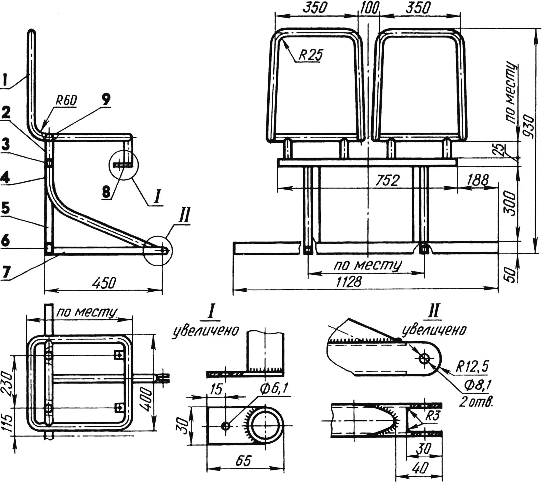
1 — seat frame (tube 22×2, 2 pcs.); 2 — seat leg (tube 22×2, 8 pcs.); 3 — support beam (tube 25x25x2); 4 — strut (tube 22×2, 2 pcs.); 5 — post (tube 25x25x2, 2 pcs.); 6 — bumper (tube 50x25x2); 7 — stop (tube 25x25x2, 2 pcs.); 8 — mounting bracket to mini-truck frame (4 pcs.); 9 — cross member (tube 22×2, 2 pcs.).
When designing the mini-truck, I was guided by the need to ensure the following: sufficient strength and reliability of the structure, good stability and controllability, effective braking, optimal placement of all units, functional arrangement of controls, comfortable seating for the driver and passenger, and finally, an aesthetic appearance.
FRAME of the mini-truck. Its basis was the “Muravey” scooter frame, to which a rear axle beam, cross members, fender mounting angles and fuel tank cradles were added.
REAR AXLE. It should be noted that the rear axle is one of the most loaded units of the mini-truck structure. To successfully resist alternating torsional and bending loads, the rear axle beam must be rigid and strong, so it is made of thick-walled tube. It is fixed at the location of the former “Muravey” steering column (at the end of the central frame knee) and reinforced with two gussets.
In addition, the beam is supported on the right and left by cross members that repeat the bend of the “Muravey” central frame knee (the latter is important so that the floor for the driver’s and passenger’s feet is even). The cross members have eyes at the bottom for attaching the sub-seat frame, and brackets for mounting the floor on the sides.
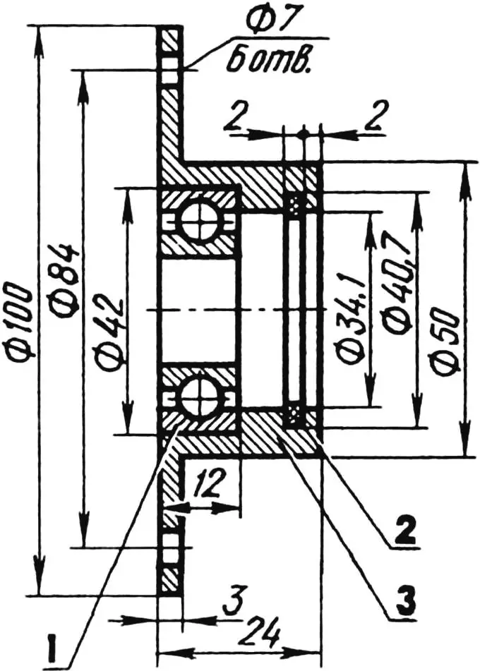
1 — bearing 104; 2 — seal (rubber ring); 3 — cover body.
A technological subtlety: I attached the rear axle beam to the frame assembled with suspensions — forks, shock absorbers and wheels. First, I tacked the beam by welding to the central knee, and then, having set it relative to the frame and finally determined the dimensions, welded it to the knee and cross members.
The 12° angle of inclination of the kingpin bushings is due to the use of wheels sized 6.70—10″ — drive and 4.00—10″ — driven. At this angle, the mini-truck frame plane is parallel to the road. The angle can and should be changed when using four wheels sized 4.00—10″.
As rear suspensions, modified front suspensions from two “Muravey” scooters are used. The modification consisted of replacing the kingpin and attaching an additional knee to the fork, strengthening the connection of the fork with the steering lever.
The sub-seat frame with driver’s and passenger seats is attached to the rear axle beam by its four upper brackets. This frame is connected to the cross member eyes by two lower brackets (loops).
FRONT AXLE, I remind you, is the drive one. It includes: reverse reducer, wheel suspensions, springs, shock absorbers, half-shafts, brakes — all from “Muravey”. With some modifications, these units are located in their former places under the body.
ENGINE of the mini-truck is “native”, T-200. Its power, due to the installation of a head with a reduced combustion chamber, has been increased to 14 hp. Instead of the standard ignition system, a “magneto” is used, which simplifies maintenance of the power unit. The engine mounting to the frame is left unchanged.
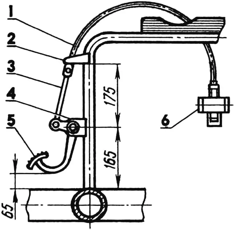
1 — cable in sheath; 2 — stop; 3 — rod; 4 — pedal mounting bracket; 5 — “gas” pedal; 6 — carburetor (engine conventionally not shown).
The torque from the engine to the reverse reducer is transmitted by a chain from a moped. For this, the sprockets, drive (z = 14) and driven (z = 27), are fitted to the mounting dimensions of this chain by reducing the thickness of their teeth on a lathe. High tractive effort was achieved by replacing the standard drive sprocket (z = 17) with a “Minsk” one with fewer teeth (z = 14). The chain drive on the “Sledopyt” performed excellently: after 800 km of running, the possibilities of its adjustment are far from exhausted. And the sprockets show no obvious signs of wear.
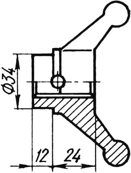
TRANSMISSION. The standard gear shift lever is replaced by a lever from a diesel engine high-pressure fuel pump, which fit the spline mounting dimensions.
The “Sledopyt” is equipped with a reverse reducer from the “Muravey” cargo scooter. Its weakest parts are the half-shafts. Under peak loads, they break because they are weakened by holes for fixing pins, and have significant play — universal joints with rubber couplings, as well as single suspension, do not contribute to a long service life of the half-shaft mounting locations.
To prevent the running gear from failing, I solved the problem radically. For this, I made new differential bearing covers, into which I pressed bearings 104, suitable for the half-shaft mounting dimensions.
1 — gear shift lever; 2 — frame knee, central; 3 — lever mounting bracket; 4 — adjustable rod; 5 — gearbox lever (engine conventionally not shown).
I also modified the universal joint forks: first, shortened them; second, turned them on the outside so that it became possible to sink the forks deeper into the covers and thereby increase the reliability of their splined connection with the half-shafts. After this, the pins fixing the forks on the splined shafts became unnecessary.
Still in my plans is the installation of wheel reducers for the drive wheels. This will improve the overall weight distribution of the structure, ease the engine’s work, and increase the tractive characteristics of the mini-truck.
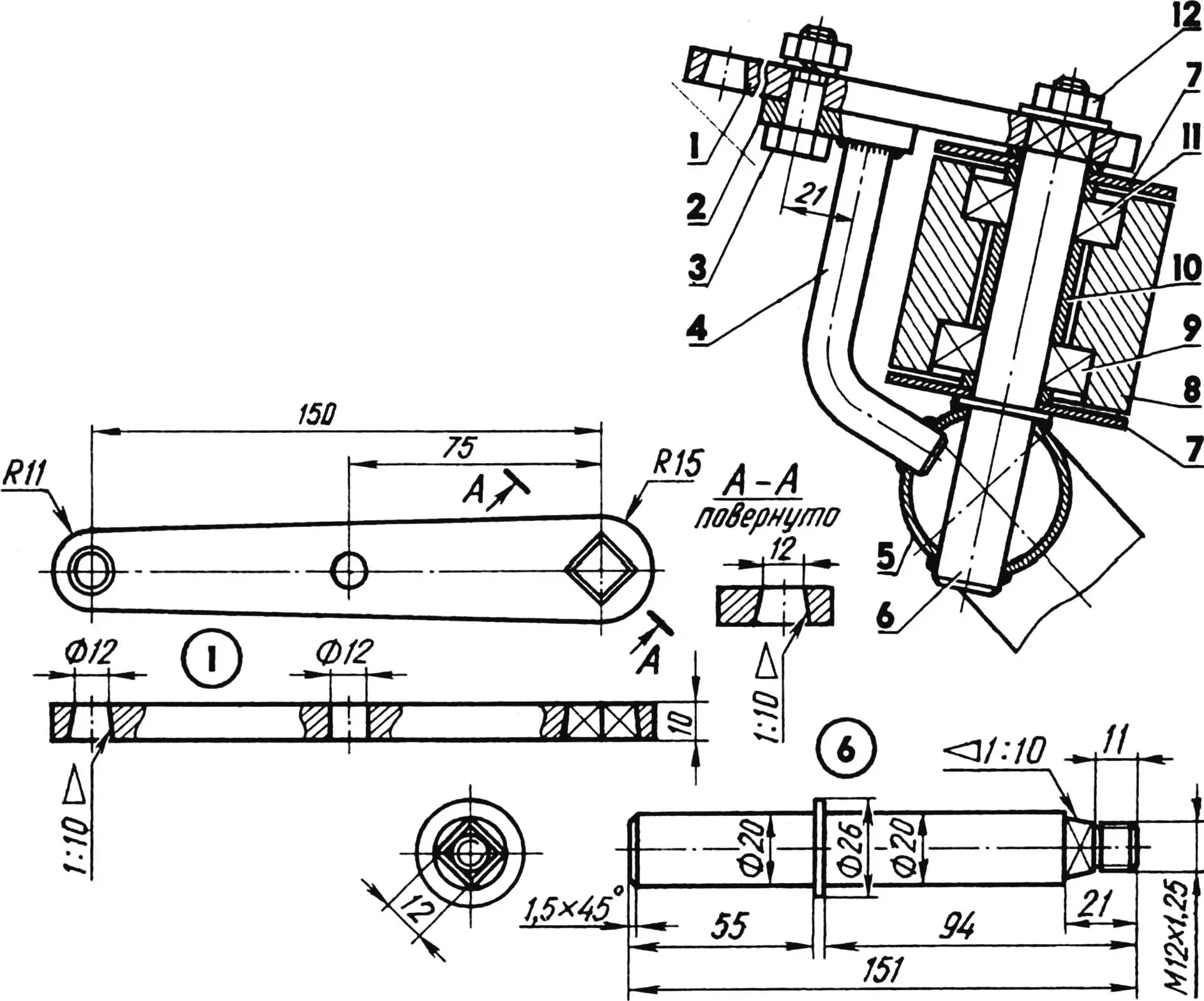
STEERING DRIVE. When placing it on the mini-truck frame, I faced the task: how, without interfering with the driver and passenger, to connect the steering wheel in front of the seats with the steering levers under the seats?
After considering several options, I used a rocker that connects the entire kinematics of the steering drive. The rocker is located at the top of a vertical shaft that rotates in two ball bearing supports attached to the central frame knee with clamps.
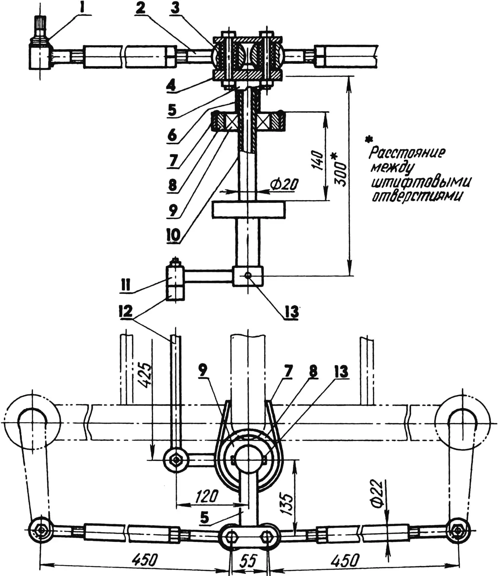
1 — ball pin (from “Zhiguli”); 2 — transverse rod; 3 — rubber-metal joint (from “Moskvich-2141”); 4 — rocker (strip s10); 5 — rocker head (tube 30×5); 6 — thrust bushings (tube 26×3); 7 — mounting clamp to central frame knee (strip s5); 8 — bearing housing (tube 77×15); 9 — bearing 204; 10 — drive shaft (tube 20×4); 11 — steering arm; 12 — longitudinal rod; 13 — fixing pins.
Steering rods of variable length are made of steel tubes and rods. At one end they have ball pins from “Zhiguli”, at the other — rubber-metal joints from “Moskvich-2141”. The rods allow adjusting the toe-in of the steerable wheels so that during movement all gaps in the steering drive under the action of rolling friction forces are taken up and the wheels become parallel.
The steering mechanism itself is taken from the “Niva” car. A homemade column with a steering wheel from “Moskvich-412” is welded to it at the top.
CONTROL SYSTEM. Speaking of it, I mean the mechanisms for controlling brakes, clutch, carburetor throttle valve, reverse reducer.
The mini-truck uses an automotive control system: under the driver’s right hand is the gearbox lever, under the left — the reverse reducer, under the right foot — “gas” and brake pedals, under the left — clutch (the last two pedals — from the “UAZ” car, modified for the installation location). As clutch and “gas” pedals, brake pedals from the “Turist” scooter are used.
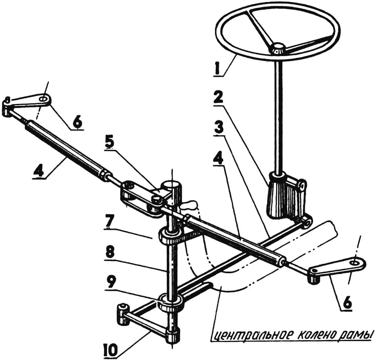
1 — steering wheel (from “Moskvich-412”); 2 — steering mechanism (from “Niva”); 3 — steering rod, longitudinal (from “Zhiguli”); 4 — steering rods, transverse, adjustable; 5 — rocker; 6 — steering levers; 7,9 — bearing supports; 8 — drive shaft; 10 — steering arm.
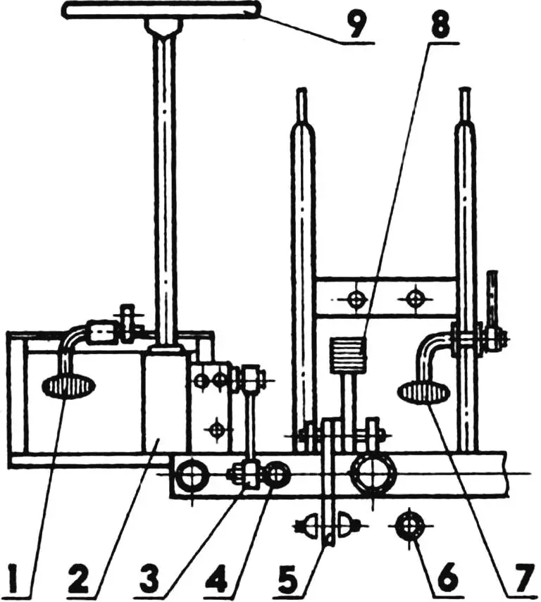
1 — clutch pedal; 2 — steering mechanism; 3 — steering arm; 4 — steering rod, longitudinal; 5 — brake lever; 6 — gear shift lever rod; 7 — “gas” pedal; 8 — brake pedal; 9 — steering wheel.
The control mechanisms for clutch and throttle valve are cable-operated; for brakes, gearbox and reverse reducer — rod-operated, rigid. The brake rods and gear shift lever rod are made adjustable in length.
The carburetor air enrichment lever (“choke”) is located under the driver’s right hand — on the sub-seat frame tube.
1 — steering lever; 2 — base plate (plate s5); 3 — bolt Ml2x1.25; 4 — additional knee (rod Ø14); 5 — wheel fork; 6 — kingpin; 7 — dust covers; 8 — kingpin bushing; 9 — bearing 46204; 10 — spacer bushing; 11 — bearing 204; 12 — nut M12x1.25.
Reliable brakes are the key to the safety of any vehicle. The engine may not work, but the brakes must always be in good working order — there is great meaning in these words. Therefore, the mini-truck design uses the standard “Muravey” mechanical brake system.
The brake pedal is connected by a rigid adjustable rod to a rocker — a brake force equalizer and further — to the drive (front) wheels. In the future, the “Sledopyt” will also have a parking brake acting on the steerable (rear) wheels.
SUB-SEAT FRAME is a simple structure welded from steel tubes of round, rectangular and square cross-sections, fastened with bolts at six points: four of them are located on the rear axle beam and two — under the cross members. If necessary, the frame is easily dismantled, leaving free access to the steering drive.
Seat frames are made of thin-walled tubes 22 mm in diameter, seat cushions and backs are taken ready-made — from transport equipment. Vertical backs provide comfortable seating for the driver and passenger. In addition, to prevent lateral displacement of riders during sharp turns, the seats were later equipped with armrests.
FUEL TANK is made from a brake system receiver of a “KrAZ” heavy truck. For its placement, the arcs of the former “Muravey” sub-seat frame were chosen: cradles are equipped on them, to which the tank is attached with clamps and rubber pads. Its capacity is about 35 liters, which is quite sufficient for long trips. Fuel from the tank flows by gravity to the engine carburetor.
WHEELS. For steerable ones, scooter tires with a fine, so-called highway tread pattern are used. They pick up less dirt, quickly self-clean, providing satisfactory controllability off-road, and create less resistance when driving on asphalt.
For drive wheels, the choice is much wider. On the mini-truck, depending on the route and driving conditions, any of four wheel sets can be installed: “native” single or paired, homemade with “aggressive” off-road tread for driving off-road, or wide-profile from the “Tula” motorcycle. The latter option is the most advantageous for the “Sledopyt”.
EXHAUST SYSTEM. Its placement was not associated with any difficulties. Here there is only one innovation — an additional elbow at the muffler outlet, which made it possible to divert exhaust gases from under the body outward — to the right. This freed the driver and passenger from the inevitability of breathing exhaust gases.
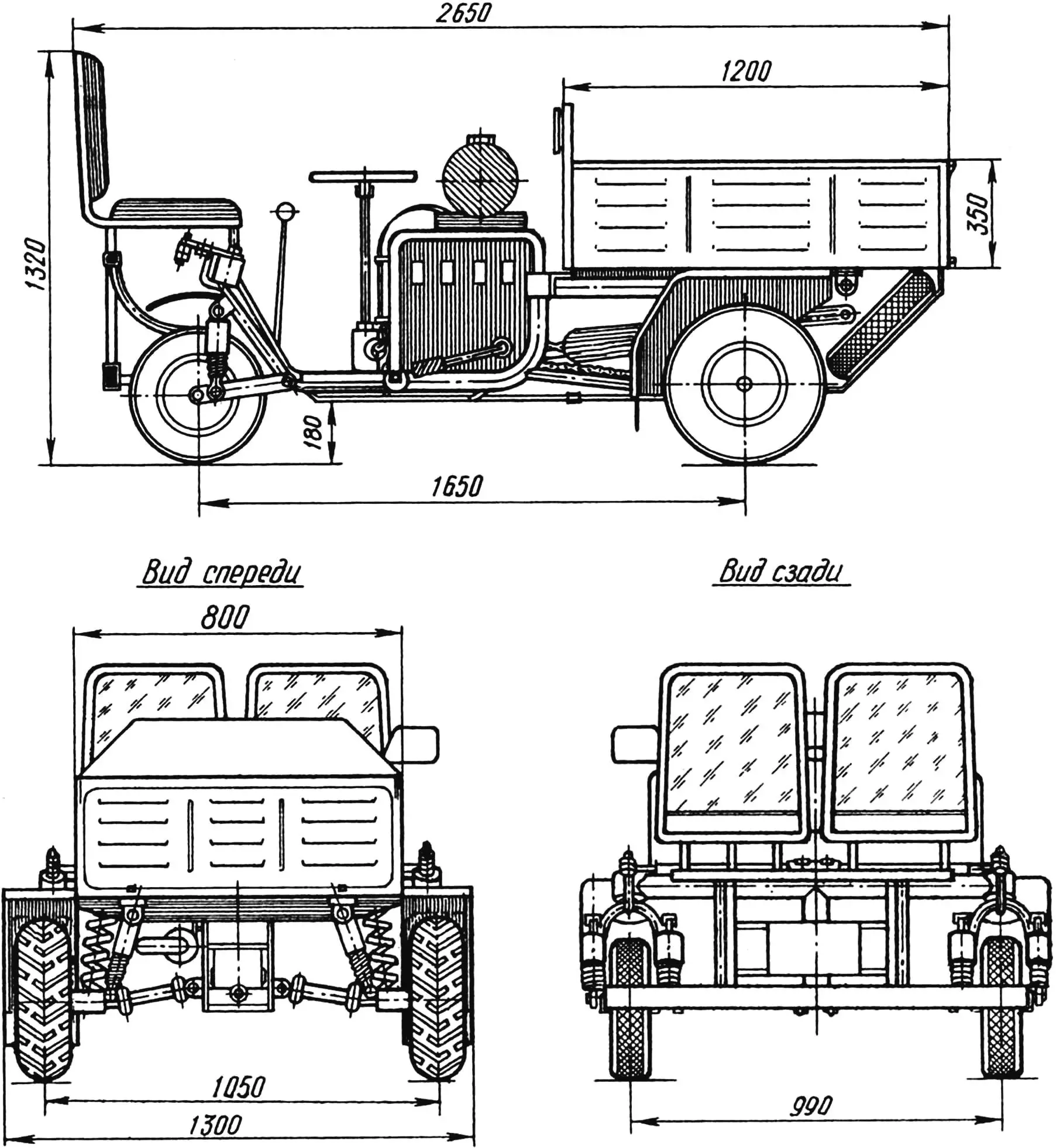
BODY of the mini-truck is homemade with dimensions of 1200x800x350 mm. Its load capacity is 300 kg.
The body is made from metal air duct sheets (sheet thickness — 1.5 mm). The sides are edged with an angle, but a small-diameter tube can also be used, having first cut a groove in it along the entire length from the bottom. The edging is attached with an intermittent weld.
The fact that the body is of a dump type is very convenient in operation. Among other things, this allows, by raising it, to perform preventive inspection and repair of the transmission without crawling under the machine!
SPECIAL EQUIPMENT. For safe driving on roads, the mini-truck is equipped with a rearview mirror and lighting equipment from “Muravey”.
This equipment also includes a rear bumper, as well as a “Zhiguli” sump guard with a spare wheel installed under the body.
To protect the driver and passenger, as well as the engine and other structural units from water and dirt getting on them, all four wheels are equipped with fenders and mudguards.
The drive wheel fenders are made from parts of a household refrigerator inner chamber body. For the rear wheels, parts of the front fenders of the “Izhevsk” motorcycle are used.
Three years of operation of the “Sledopyt” have shown that it is quite viable. The mini-truck’s good design is attractive — many take it for an industrial sample.
Based on the “Sledopyt”, a four-wheeled motorcycle, mini-tractor, as well as an all-terrain vehicle on pneumatics can be made. Any of these machines will ease the work of a summer resident, farmer or builder.
TECHNICAL SPECIFICATIONS OF «SLEDOPYT»
Overall dimensions, mm:
length 2650
width 1300
height 1320
Wheelbase, mm 1650
Track, mm:
front wheels 1050
rear wheels 990
Ground clearance, mm 180
Weight, kg 175
Maximum speed, km/h 40
Load capacity, kg 300
Fuel consumption, l/100 km 5.6 — 6.2 (depending on drive wheel diameter)
«Modelist-Konstruktor» № 10’2000, S. YAKISHEV
Recommend to read
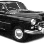 GAZ-12 “ZIM”
Executive car GAZ-12 "ZIM" was intended for managers of the second echelon of state power (Ministers, secretaries of regional committees, chairmen of Executive committees, etc.) and had...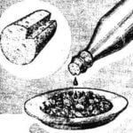 CULINARY PIPETTE
Soft metal cork-cap on the bottle with vegetable oil after opening, is usually vented, and the usual on the slippery bottle to use uncomfortable, and the hosts often do not clog the...
