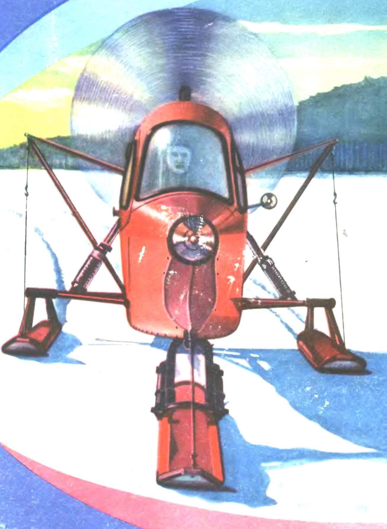
 “In the past I Aviator, wrote the Director of station of young technicians Ufa refinery P. S. Astashkin, and for obvious reasons I wanted to build a snowmobile that resembled a plane. After all, the best part of his life to aviation started at the flying club, finished in guards red banner assault regiment, which took place from the Volga to Berlin.
In the design of the sleigh I was based on the well-proven in aircraft truss fuselage welded from thin steel tubes. Sheathed his leaf aluminum variable thickness (0.5 to 1 mm). Suspension — trehmernoi scheme, with the front steering ski and symmetrically arranged rear. Diagram of the machine in three planes is shown in figure 1. The case has a fully enclosed double cabin (Seating arrangement — each other) streamlined contours smoothly blend in with the hood a twin-cylinder engine M-52 “Sport” (a motorcycle of the type “Ural”), which via a standard gear box rotates the pusher propeller. Access to the cabin through the door opening forward and sideways. The cabin has a large glass area, and combined with mirrors, automotive-style a good all-round visibility.
Management. Management system is also unusual snowmobile steering ski controlled, airplane, foot pedals, handle passes the command to the clutch and the brake. Gaza — when moving forward the speed of the motor increases, the back — decrease. Motorists may this system do not like: they are accustomed to a conventional steering wheel, but I like the pilot, it is convenient. However, to replace the pedal by the actuator on the steering wheel will not be easy.

Fig. 1. Scheme in three dimensions and principal dimensions of snowmobiles ASP-3:
1 — headlight, 2 — handle, 3 — antenna, 4 — top gas tank, 5 — sensor tachometer, 6 — trunk, 7 — lower the gas tank, 8 — seat, 9 — the lower shoulder of the control knob.

Fig. 2. Design and basic dimensions of the frame:
And the contours of the main frames, B — the outline of the bow (side view); B — General view of the frame: 1 — Hoop lights, 2 — lower spar, 3 — side side rail, 4 — rail tie rack, 5 — steering rack, 6 — tube transverse frame, 7 — frame № 1, 8 — angular front windscreen, 9 — the arc of the roof frame, 10 — frame № 2, 11 — roof rail, 12 — frame № 3, 13 — lower roof rail, 14 — brace, 15 — Hoop of the bonnet, the 16 — sub-frame, 17 — upper strut Assembly, 18—, 19 — the front engine mounts, 20 — spring strut, 21 — axle shaft rear skis 22 the see — saw suspension, 23 — reinforcement of the gusset plate 24 to the balancer, 25 — frame of the rear seat 26 and the frame of the front seat 27, the lower cross member, steering rack, 28 — plug attachment of the steering ski.

Fig. 3. The scheme of control and location of main components:
1 — the cable pulley run 2 pen run 3 — clutch lever, 4 — brake handle 5 — tachometer 6 — wiring the tach, 7 — wiring the ignition switch, 8 — tachometer sensor on the engine, 9 — duplici lever shifter, 10 — kick, 11 — recoil brake, 12 — scraper brake, 13 — rope of the Gaza strip and 14 cables shifter, 15 — clutch cable, 16 — wire rope brake, 17 —lever of the gear selector, 18 — the lower shoulder of the control handle, 19 — video cable foot control, 20 pedals, 21 — foot control cable, 22 — fork the steering of the ski.
Fig. 4. The shaft of the propeller.
Rotor group. The regular gear box is used for the selection of turnover, the most relevant step of the screw and driving the sled. So riding your sled in first gear, which used the screw a few easy, we include a second (as is done on cars and motorcycles), and the engine is properly loaded. It turns a threefold benefit: eliminates the need for the manufacture of variable-pitch propeller, ensures that the engine start from the cockpit using a rope and wires to kickstarter, which is convenient and safe, and finally, the possible heating-up and adjustment of the engine at neutral gear position, and then sampling when the screw in any gear. In order to bend the axis of the propeller, the box turned 180° and used a homemade counter shaft (Fig. 4), which serves both the shaft of the propeller. Accordingly, the bearing had to be replaced on roller radial thrust, which receives axial force from the thrust force of the propeller. Gear 1st and 2nd gear put on the shaft of the screw, and the other is put the bushing-restrictor.
The propeller (Fig. 5) made of pine gorse (strips), glued to the package with epoxy glue and after processing the profile with contraband covered with two layers of fiberglass, ASTT(b).
The screw is not quite the usual way is mounted on the shaft between the latter and the propeller hub includes a flexible coupling (Fig. 7). It connects with the shaft by dowels or splines, and the screw sits on the cone shaft tightly, but without pins. The flange coupling has four tabs (round toes), which are included in the corresponding holes of the bushing where pressed rubber liners. The hub nut is tightened so that she was sitting on the cone shaft without backlash, but was able with little effort to rotate by hand. This system ensures smooth gear shifts, protecting parts against premature wear.
I have said before that in first gear the engine quickly spins up and goes to the best operating mode.

Fig. 5. Air screw: top view and side view.

Fig. 6. The propeller hub

Fig. 7. The design of the elastic coupling connecting the propeller hub to the shaft.

Fig. 8. Construction under the engine frame and suspension skis.
Pull up to 130 kg, the sled go easily, but slowly. The one who will want to repeat this design, after enabling the second gear the engine can dramatically dump momentum, the attraction will start to fall. This means that the screw is heavy. To remedy the situation, it is necessary to make either a new pair of gears with the degree of reduction of 1-3 (ratio nominally equal to 2.28) or other screw with such parameters: Ø 1500-1600 mm, pitch 500 — 600 mm. tai will have to do if it used the engine less power about 25-30 HP Economically viable mode of operation of the engine: 3500-4000 rpm in second gear; the speed of the sled at the same amounting to about 40 km/h.
Some recommendations for starting and pulling away:
1. If the gear is engaged and the ignition is off several times to turn the screw. In a strong frost it is sometimes useful to turn out the candles.
2. Screw the candles, open benzaken, turn the screw 1-2 times.
3. Sitting in the cockpit, the gear lever put into neutral, remove the gas completely, the lever to adjust the ignition timing set on “later”, close the diffuser carburetors valves.
4. A handle and cable connected with the lever the kick starter several times to turn the crankshaft. After that, turn on the ignition and a vigorous pull will start the engine, keeping the revs in the Gaza strip.
Finally, run the engine at low, then medium speed. Remove the gas. Squeeze the clutch, look around, and if there are no people and no obstacles, include the first transfer, at the same time adding gas. It remains to disperse the snowmobile to a speed of 30-40 km/h, squeeze the clutch, remove the gas and to include the second transfer, smoothly and on time adding momentum to the engine.
Remember! At the time of gear shift propeller it is necessary to slow down to avoid sudden jerks and bumps. For this purpose a lever with a rubber boot abutting the disk of the sleeve under the action of cable tension associated with the lower ends of the Gaza strip.


