
 Every radio Amateur knows how it is sometimes difficult to find in electronic equipment, faulty transistor, especially when there is no instrumentation. From the diagram it is necessary to use almost all transistors until you find the “culprit” of the failure. I tried to test the transistor directly into the circuit, not Vipava it.
Here’s the essential our device. It allows you to easily and quickly find the faulty transistors, not Vipava them from the scheme. Indicators are the lamp of the flashlight.
The probe is a blocking oscillator in which the subject transistor T1 (Fig. 1) is an active element. If he doesn’t, the blocking oscillator generates pulses supplied to the thyristor D1. In its anode circuit is included the lamp L1. A control pulse is supplied to the thyristor D1 in the moment of transition of the tested transistor from the open condition of n closed. Then, if he punched the collector-emitter transition, not false inclusions D1.
The ability to test simultaneously two transistors connected electrically (Fig. 2), extends the scope of the probe. In this case to obtain a generating mode input positive feedback via the additional capacitor C2.
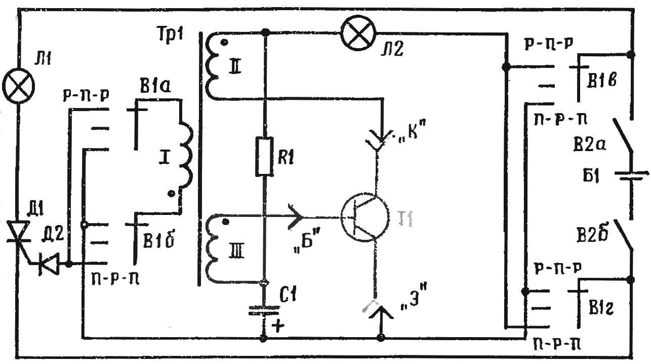
Fig. 1. A schematic diagram of a probe for testing transistors: R1 20 kω, C1 20 UF, D2 Д7А — W
Figure 3 shows a universal scheme that combines both functions. On the cover of the instrument housing installed two lamps, switch the litany of jacks for connecting the probes, switch the conductivity type of transistors (n-p-n or p-n-p). Transformer TR1 is wound on the core Ш6,4X6 mm (pocket radio). The winding of I contains 400, and the winding II and III — 200 turns of wire PEV-2 0,12. Indicator lights L1, L 2 h6-60 (KM-1) or MNZ.5-0,14, V1 — the disk toggle ПГГЗП4Н, B2 — switch TP1-2, D1 — thyristor Д235А or НУ201, condensers — K50-6, resistors — the MLT-0,5. The probe is powered from the battery 3336L (KBS-L-0,5).
N device connect a known good transistor and check generation. For this purpose one of the windings of the transformer TR1 is connected to the oscilloscope or phone. If the generation of no, the terminals of the windings II or III must be reversed.
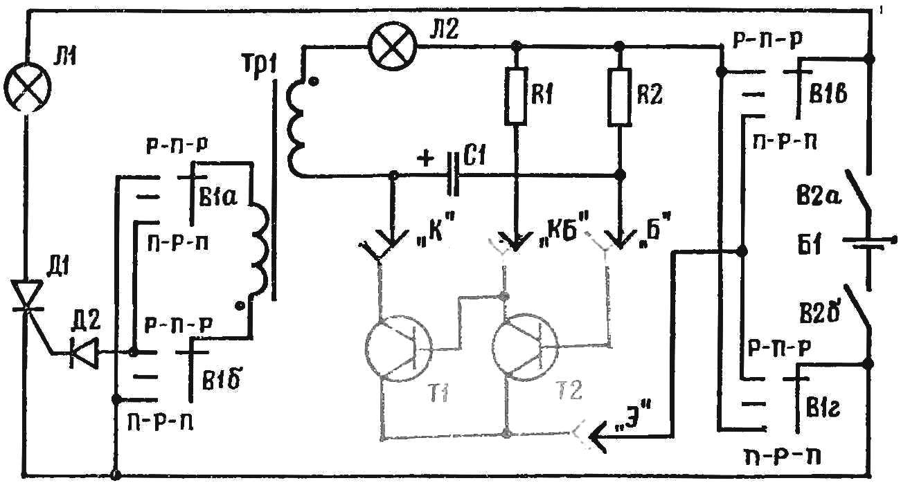
Fig. 2. Schematic diagram of probe to test pairs of transistors with electroplated bond: R1 5.1 kOhm, 30 kOhm R3, C1, C2 20uf, D2 Д7А-J.
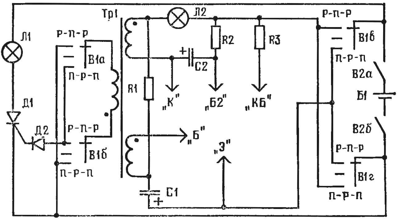
Fig. 3. Schematic diagram of the universal tester to check transistors: R1 20 kOhm 5.1 kOhm R2, R3 30 kω, C1 20 UF, D2 Д7А — J.
Lamp L1 should turn on when the open probe “C” and “3”. If it lights up when the circuit of these probes, we need to swap the insights of one of the windings of transformer Tp1.
The smaller the resistance of the resistors R1 and R2, the greater the current the device consumes from the power source and more powerful transistors can be checked.
When working with the device to terminals of the test transistor connecting the probes “a”, “K” and “B”. The switch B1 is set to the “n-p-n or p-n-p” and turn on the power. When the lamp L1, the subject transistor is suitable. If the lamp L2, it is necessary to verify whether the test transistor in circuit with a galvanic connection (see Fig. 2) if not, then prometeo collector-emitter junction. Otherwise, you need to connect and styli “KB” and “B2”. Now the burning lamp L1 indicates that both transistors are suitable. But if it is not lit, then one of the transistors need desoldering and test each separately.
When both of pampas are not lit, this indicates that the transistor has failed.
A. RUBANOV, Stavropol
Recommend to read
 SURVIVE INTERIOR LIGHT AND LAMP
Unfortunately, the real service life of bulbs and shades in lightly places their exploitation is often not as long lasting as I would like. Break the bullies, twisting the bottom-feeders... A SCOOTER OR CITY BIKE?
Less and less will see on our roads a nimble scooter. This is not surprising: the main producers and their fates were abroad — in Latvia and Ukraine. So what else from this series is now...
