 The domestic industry for many years produced mopeds and motorbikes with engines of the type “D”. However, all of these machines were a significant disadvantage (which was, however, pay for their low price). The fact that these motors had a single transfer, which significantly reduces their opportunities. So, for them it was almost impossible to budge without preliminary acceleration by foot pedal; connect to motor “human power” I had when driving uphill or on a dirt road, and when driving on the highway the scooter would not prevent accelerating transmission, allows to increase its speed at least 50 km/h.
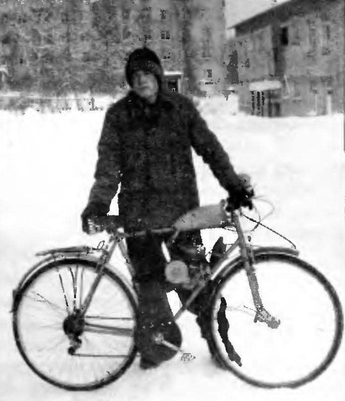
All these deficiencies deprived of a motorbike created by a team of young technicians “planet” of the city of Izhevsk under the direction of R. V. Cheraneva on the basis of the four-speed bike “Tourist” and the once-widespread engine D-8. When the engine was running rear wheel drive is effected via an intermediate gear and an additional sprocket of the pedal. The pedals remain stationary. To move on foot, normal for the bike mode, simply turn the engine off and the clutch.
Engine D-8 using regular clamps attached to the frame of the bike closer to the steering column. To increase the power of the engine, the height of the combustion chamber is reduced by 2.5 mm. the Silencer (on motor bike) had to slightly modify to be able to set it close to the cylinder as the chainsaw “Friendship”. Fuel tank — standard with a capacity of 2.5 liters, is mounted to the top tube of the Bicycle frame.
With the drive sprocket of the motor rotation through the chain is transmitted to the intermediate gear. This node is entirely self-made, and its design will discuss the Basis of axle reducer is from steel 40X, which is two ball bearings (201 and 202) is mounted in the sleeve-body made from duralumin brand D16T.
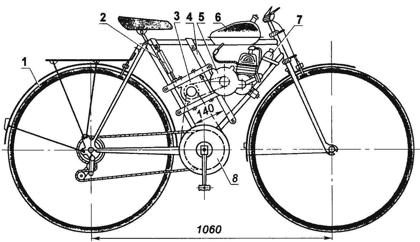
Fig. 1. The layout of the bike:
1 — bike “Tourist” with 4 gears, 2 — thunder — vertical chain tensioner intermediate, 3 — intermediate gearbox with horizontal tensioner 4 — sub-frame; 5 — engine D-8, 6 — tank; 7 — damper, 8 — pedals
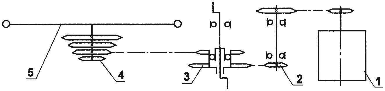
Kinematic diagram of the drive:
1 — engine D-8,2 — intermediate gearbox, 3 — block sprocket pedals with a freewheel (ratchet-odnorodnoi off the bike “salute”); 4 — block of sprockets of the gearshift, 5 — rear wheel
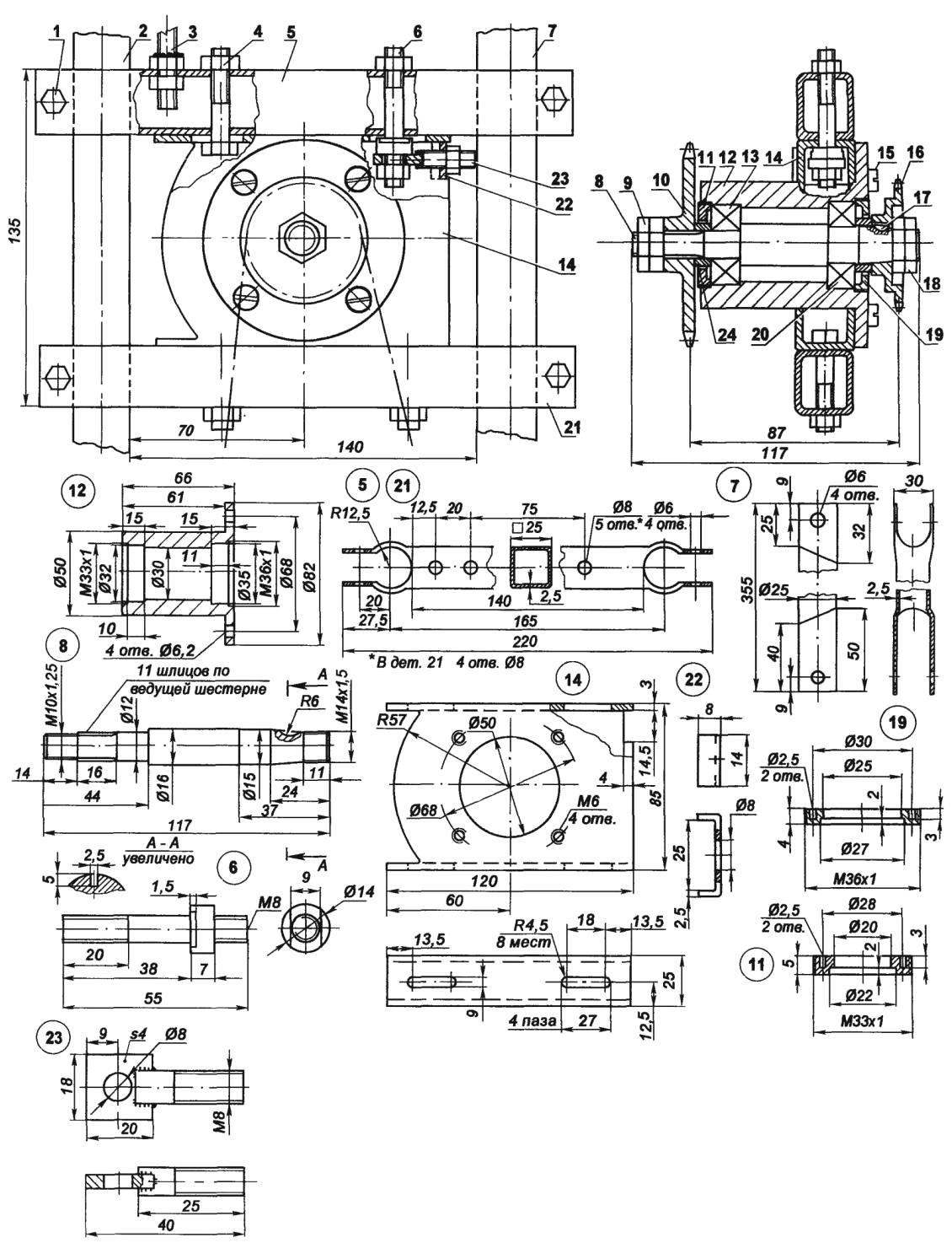
Fig. 3. Intermediate gearbox:
1 — mount jumpers (bolt M6, 4 pieces); 2 — seat front bike frame (tube Ø25); 3 — vertical tensioner; 4 — mount housing (bolt, nut M8, 3). 5 — upper jumper wire (steel, pipe 25x25x2,5); 6 — the horizontal emphasis of the tensioner (M8 stud), 7 — subframe (steel pipe 25×2,5); 8 — shaft (steel 40X, lap 16); 9 — mount the driven sprocket (nut M10x1,25, 2), 10 — sprocket driven (z = 16, from moped “Verhovina”); 11 — bearing cover 201, 12 — bearing housing (duralumin D16T); 13 — the bearing 201, 14 — the case intermediate gear (duralumin D16T, pipe 85×25); 15 — fastening the bearing housing (screw M6,4 pieces); 16 — sprocket (z = 10, from the engine D-6); 17 — segment shear; 18 — mounting the drive sprocket (nut М14х1,5, 2 PCs.); 19 — bearing cap 202; 20 — bearing 202; 21 — lower jumper (pipe 25x25x2,5); 22 — bracket tensioner (steel, band 2,5×14); 23 — spec-bolt horizontal tensioner, 24 — remote bushing (2 PCs)
In the manufacture of axes because of the lack of special equipment, difficulties arose with the processing of the slots. In this regard, applied to a primitive, but effective technology After the turning process, the workpiece axis in a vertical position, rigidly clamped in the vise thread M10x1 up. The workpiece was attached sprocket z – 16 (with slots) and end abruptly, and was greatly struck with a heavy hammer as the sprocket is hardened to 55 — 60 LDCs, and the axis cannot be thermally processed, at the end of a cylinder shaft with a diameter of 12 mm appeared clear prints 11 slots, as in the hole in the sprocket Further processing was carried out on a lathe the axis of the fixedly clamped in three-jaw Chuck and was propped up by the tailstock center Specially sharpened cutter is fastened in the tool holder, the front surface in the direction of the cartridge Cross-feed of the caliper tip of the cutter was applied to the marked end of the axis and longitudinal pitch, when working on a planer, layer by layer gradually processed groove slot, leaving only a small allowance for final operation After pre-processing all of the slots, the workpiece is again clamped in a vise, and with a star as a broach, finally formed splined surface.
The splined end of the shaft is secured the driven sprocket with 16 teeth (from the moped “Verhovina”), and on the other, to segment the key — 10-bevel sprocket from the engine D-6. Each sprocket is secured by a nut and lock nut Between the bearings and the sprockets are installed remote rings and covers, which perform two tasks: protect the bearings from contamination and fix them in the sleeve (this is insurance in case the nut on the axle will spin)
The host of stars is fixed in the gear housing manufactured from window profiles — aluminum rectangular pipe with a height of 85 mm, a width of 25 mm and a wall thickness of 3 mm Assembled intermediate gearbox bolts M8 is fixed to the two crosspieces of steel square tube 25×25, which, in turn, are fixed on a seat tube of a Bicycle and additionally installed parallel to the subframe.
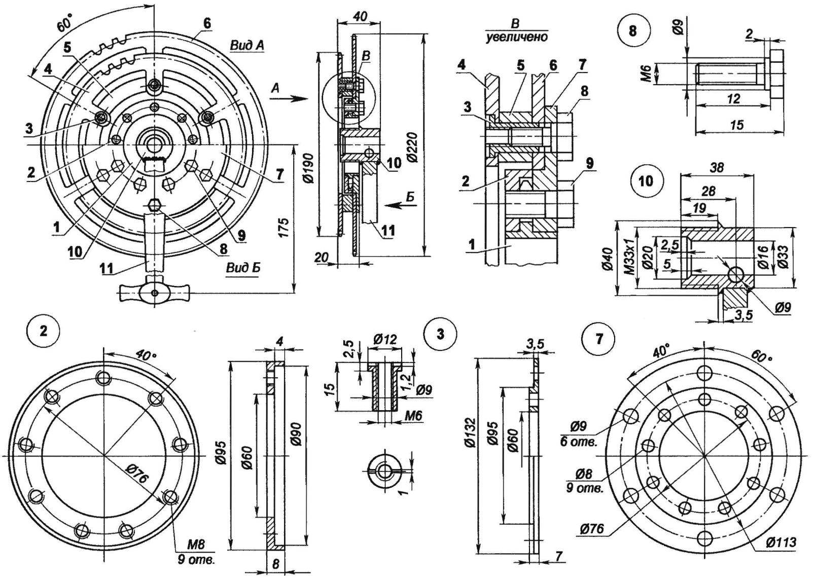
Fig. 4. Pedals:
1 — ratchet-sprocket (from a Bicycle “Salyut”); 2 — puck mounts ratchet (duralumin D16T); 3 — nut-piston M6 (steel, circle 12, 6 PCs); 4 — sprocket (g = 43, off the bike “Sputnik Sport-highway”); 5 — remote spacer (duralumin D16T); 6 — sprocket driven (z = 53, off the bike “Sputnik Sport-highway”); 7 — plate of the pedal sprocket (steel 40X); 8 — special bolt sprocket (M6, 6 PCs); 9 — securing ratchet (bolt M8, 9 pieces); 10 — bushing rod (steel 40X); 11 — the connecting rod (standard)
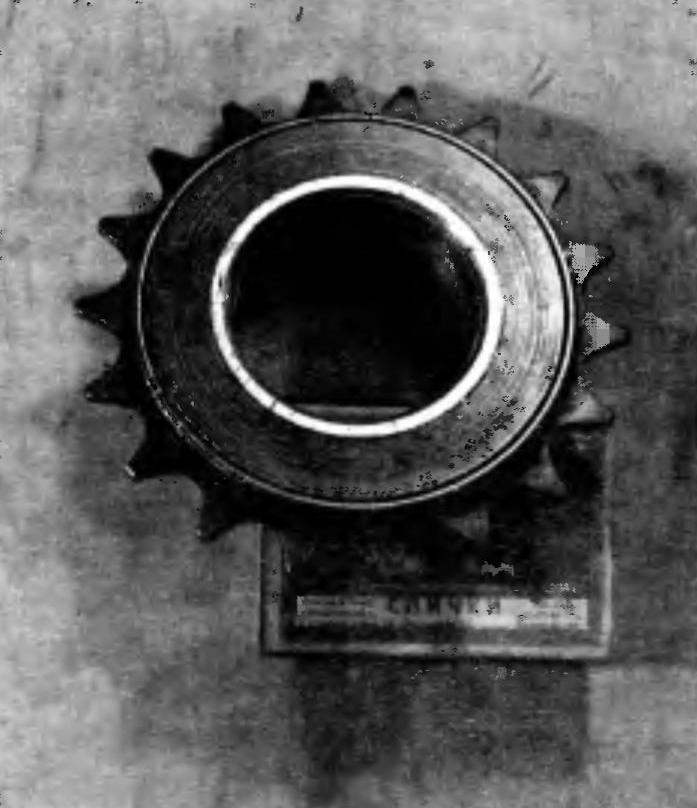
The ratchet-sprocket of a Bicycle “Salyut”
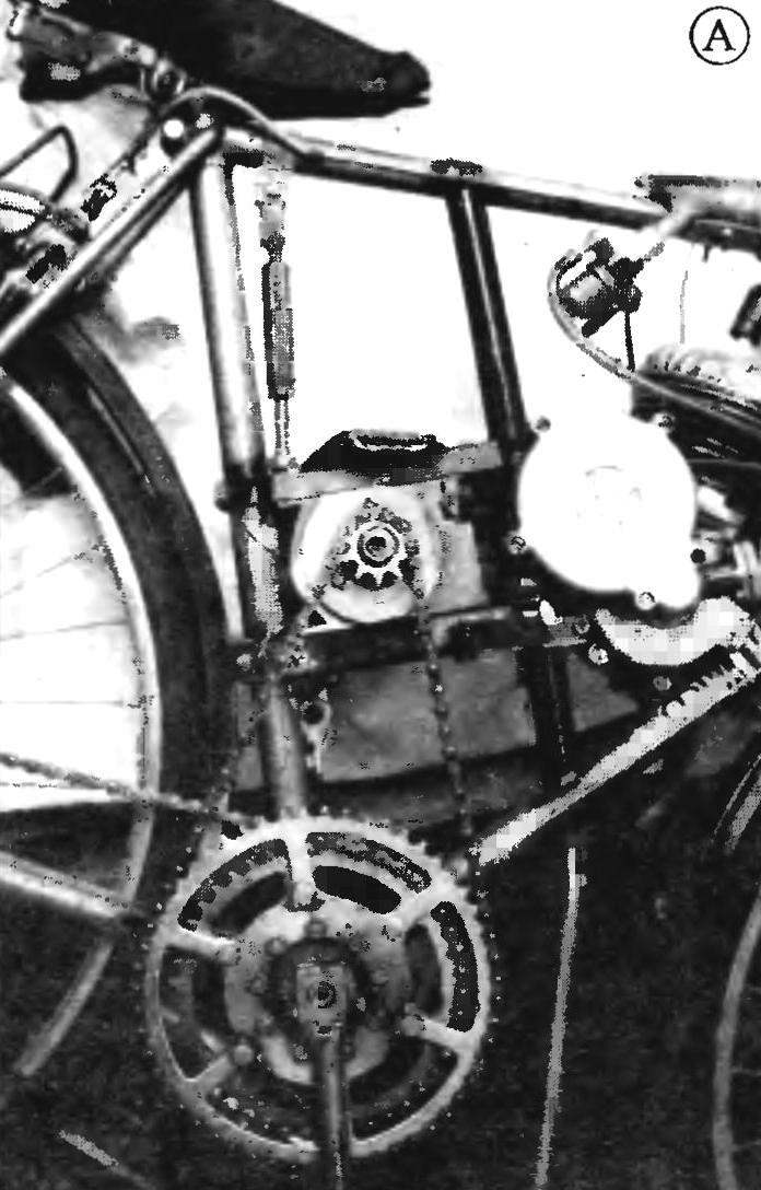
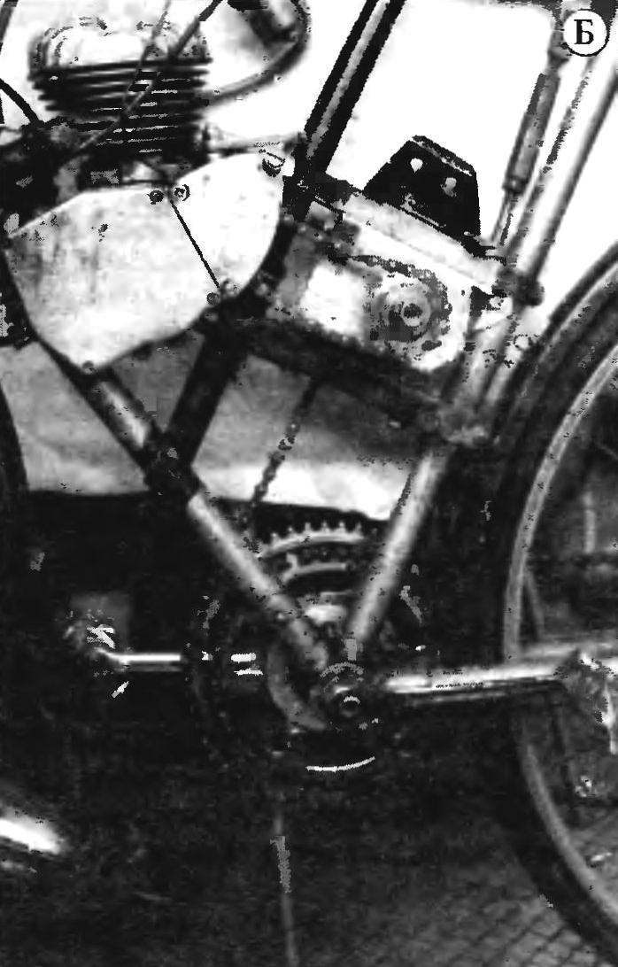
The mechanical drive of the bike:
A — side view of the pedal; B — view from the opposite side
With the sprocket gear, the rotation is transmitted to pedals. Its design know — how of young technicians of syut “planet”. This site brings sports bike Tourist in two modes: traditional (with the treadle) and the motor, allowing you to quickly and effectively implement the switching from one to another (This ability is bike attracted great interest on the part of trainers and riders participating in the evaluation of works by young technicians at the national contest Because in order to successfully lead the training of their athletes, the coach should be with cyclists generally, it uses a motorcycle or car. But the trainer was more important to be equal with athletes conditions, i.e. to sit on the bike and pedaling).
The base part of the pedal (pic 4) is a disc (7). In the Central hole of 60 mm diameter is inserted into the ratchet-sprocket (1) from the bike “salute” and pressed the special washer (2) using 9 bolts M8 Bolts are arranged with an interval of 40° and pass between the sprocket teeth, which in this case performs the role of a tough clutch. On the cylindrical band of a disk with a diameter of 95 mm is mounted with the driven sprocket (6) z = 53 of the intermediate transmission. Then through the spacer (5) is joined by sprocket (4) z. = 43. Both sprocket — bike “Sputnik Slort-highway” is used without elaboration. Fastening them together to drive is nuts-the caps (3) with M6 bolts (8) length of the nut is chosen such that it passed through the driving sprocket, the spacer and partially included in the ring Bolt M6 Allen head has a cylindrical belt with a diameter of 9 mm, which is included in a corresponding hole in the disk. This design of fastening elements required to ensure the accuracy of the connection of stars. At the end of the Assembly of the pedal into the threaded hole of the ratchet screwed the bushing of the connecting rod (10) welded to it standard connecting rod.
Now a few words about the technology of assembling and adjusting the engine transmission. To begin with the installation of the pedal. Then the intermediate gearbox with the ridges and mounted on them by the tensioners attached to the seat tube of the Bicycle. After that, the pipe connects the subframe with the ridges, with the upper and inclined tubes of the frame. The engine and chain are mounted last. The most important thing at this stage of the Assembly — do not tighten the fasteners to lock: the jumper and the housing of the intermediate gear must have freedom of movement for the implementation of the chain tension.
First, it regulates the motor circuit. This intermediate gear to shift along the jumper toward the seat tube of the Bicycle. This operation is carried out by horizontal tensioner (Fig.3). Through the right groove in the top shelf of the housing (14) and two holes of 8 mm diameter in the upper crosspiece (5) is inserted a special thrust pin (6) and is fixed on the nut Flats on the cylindrical lug studs protect it from turning when tightening. On the lower threaded end of stud put on a plate the head of setbolt (23) horizontal tensioner. The bolt goes through the hole in the bracket (22) mounted in a rectangular groove of the housing. On the bolt (23) M8 plain nut is screwed, through which you can move the reducer and, consequently, tension the motor chain. After adjustment of the final tightening of the thrust stud.
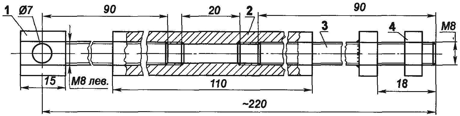
Fig. 5. Vertical tensioner:
1 — top of the threaded rod (special bolt M8 LH), 2 — housing (hexagon 19, L110); 3 — the bottom threaded rod (stud M8 welded nut); 4 — fastening the tensioner to the top bridge (nut M8)
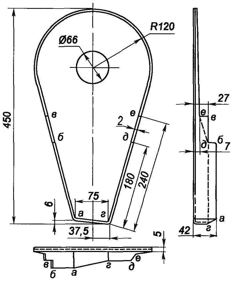

Fig. 6. Casing intermediate chain transmission
The tension of the intermediate circuit (from the reducer on the driven sprockets of the pedal) is manufactured by thunder with a vertical tensioner (Fig.5). The lower threaded rod is attached to the upper crosspiece from the inside (see Fig.3). This is necessary to ensure that mounting nut does not interfere with the movement of the housing when adjusting the first circuit.
Top pin for an elongated hexagonal head with fixed clamp on the top tube of the Bicycle frame. It should be noted that vertical movement of the reducer does not affect the tension of the motor chain.
After the final adjustment of circuits is required to tighten all bolts and nuts of fastening of lintels, frame and the housing.
Here I would like to note that it was originally supposed to do one tensioner is a turnbuckle. But to ensure the optimum tension of the two chains at the same time proved impossible.
And finally, a few words about safety. To prevent injury, which can cause the movable elements of the drive (sprockets, chains), it must be covered with protective screens or covers. The photo and figure 6 presents a General view and drawings of the most complex in the manufacture of the casing, closing the intermediate gearbox, chain and pedals. This casing is made in the same way as the other protective elements are made of sheets of polystyrene thickness of 2 mm by extrusion.
Technology following. On a thick Board or plywood is drawn at full size inner contour of the casing and marked the center hole with a diameter of 66 mm using a jigsaw on the markup is cut out the template, then stripped of its irregularities and rounded edges. In the planned center, drilled a corresponding hole, is fixed a cylindrical rod-clamping diameter 30 — 40 mm. wall of the notched hole in the remaining part of the Board subject to the same revision as the template. In the future it will serve as a matrix.
The rod casing is made with a large seam allowance on the contour. The holes it are drilled 2 — 3 mm larger than the diameter of the striker. Next, the billet is subjected to heat treatment: slowly heated in an electric furnace (muffle type) to a temperature of 180 — 190 degrees, periodically turning it. Gradually, the polystyrene softens, becomes plastic and malleable. Then carefully but quickly (to keep it hot) is put on the workpiece by the hole on the clip and crimped hanging the edge of the Board matrix. After cooling of the wall are cut along the contour of the casing with scissors, hacksaw, metal or red-hot nichrome filament, and the hole rastaquouere up to a diameter of 66 mm.
Technical characteristics
Engine power, HP………………………..2
Maximum speed, km/h………………..73
The weight of the bike with the engine, kg……….21
R. CHEREPNEV, Izhevsk
Recommend to read
 SINCE THE BATTERIES “DO NOT PULL”
It happens that the recorder or the player when you rewind the tape "do not pull" due to the large current hooked the batteries. And in many electronic games such as, Brick game... AND ILLUMINATES AND WARMS
Most aquarium fish — loving, so even room temperature water to cool them, it must be heated. They need additional lighting. "Kill two birds" will allow such accommodations. On the...
