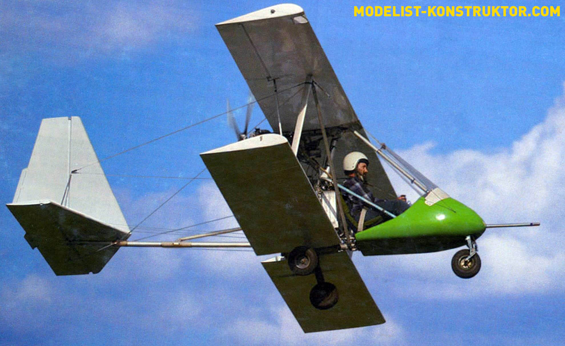
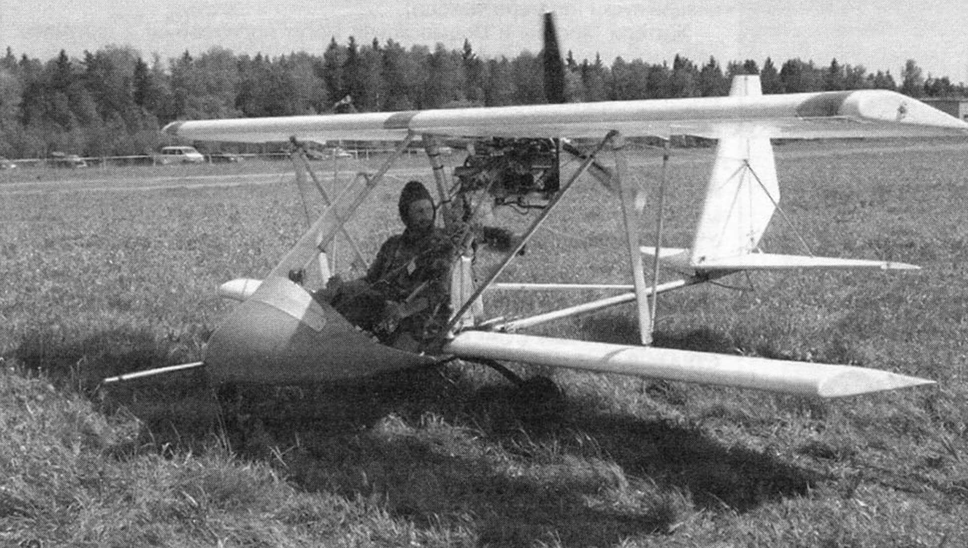
Last summer, the head of the aviation club of the Vnukovo House of Culture (Moscow), amateur pilot Andrei Chernikov, demonstrated quite complex aerobatic maneuvers over the Razdolye airfield in the Vladimir region on a single-seat biplane he designed and built with his own hands.
The aircraft does not yet have an airworthiness certificate due to financial and organizational difficulties. However, it was built in accordance with the requirements for aircraft of this type. Today Andrey Aleksandrovich presents his plane to the readers of our magazine.
Before we begin to describe the design of the aircraft, we will have to tell you a little about the history of its creation. And an ultra-light aircraft (SLA or ultralight) was created in the aircraft design circle at the Vnukovo Palace of Culture. The guys, as in other similar circles, built various sports models and performed (and not without success) in competitions. Mastering the basics of the theory and practice of creating aircraft, the circle members came up with the idea of building a real airplane – albeit small, but on which one could take to the skies.
The next stage was the choice of the aircraft layout, its layout and design.
The first thing that guided the choice of design was its cost. It is clear that the simpler the design, the cheaper it is. But the main criterion was still reliability, and therefore safety. For this purpose, they chose both a biplane design and a power plant with a pusher propeller. With this arrangement, the rotating propeller is protected in front by wings with struts and struts, and on the sides by braces. In addition, with this arrangement of the propeller-engine installation, nothing limits the pilot’s forward view, and the engine exhaust from the muffler remains behind. Savings were achieved by using inexpensive and non-scarce, but repeatedly tested materials, components and assemblies.
Frankly speaking, most of the work on the construction of the aircraft, fearing that the first pancake would not come out lumpy, and to speed up the process, I did myself, in my free time from circle duties.
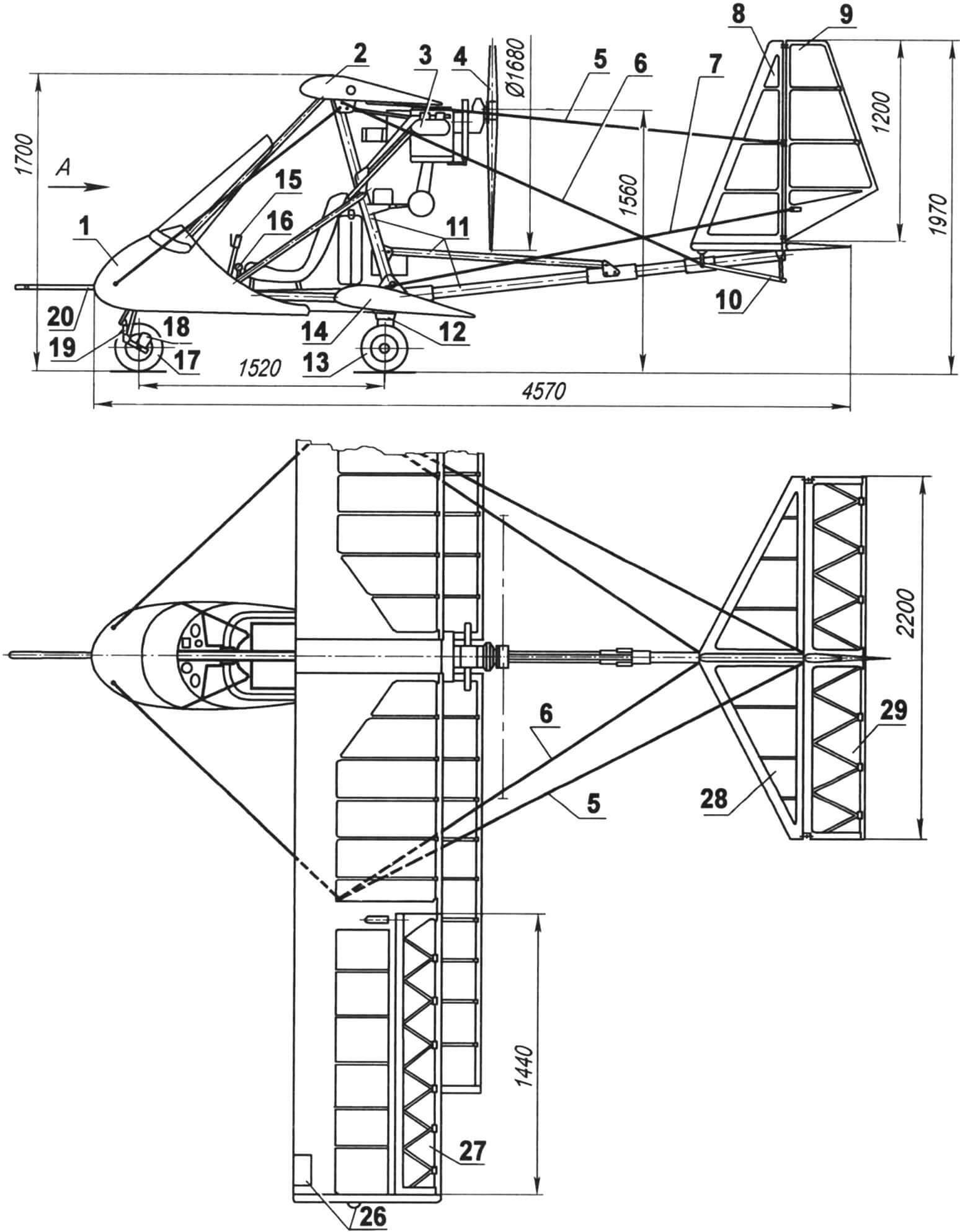
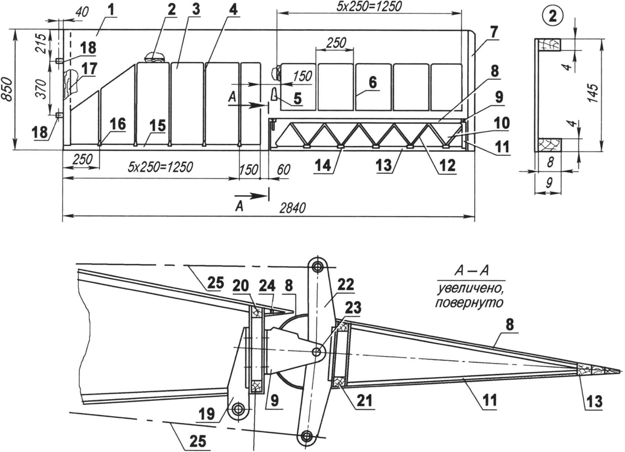
1 — fairing with windshield; 2 — upper left half-wing (right — mirror image); 3 – engine; 4 — propeller; 5 — keel brace (cable Ø1.8); 6 — brace; 7 — rudder cable wiring; 8 – keel; 9 — rudder; 10 – heel; 11 — power set; 12 — spring of the main landing gear wheels (steel plate); 13 — main landing gear wheel; 14 — left lower half-wing (right — mirror image); 15 — aircraft control stick; 16 — engine control lever; 17 — front (steer and brake) wheel; 18 — brake mechanism; 19 — front wheel stand; 20 — air pressure receiver; 21 — biplane strut (2 pcs.); 22 — strut of the upper half-wing (2 pcs.); 23 — front braces (cable Ø1.8); 24 — stabilizer and keel strut (D16, pipe Ø14×1, 2 pcs.); 25 — additional biplane rack (2 pcs.); 26 — headlight and navigation light (2 sets); 27 — aileron (2 pcs.); 28 — stabilizer; 29 — elevator; 30 — trim (duralumin s0.5)
The power structure of the aircraft is a flat truss assembled mainly from duralumin pipes with a diameter of 60 mm and a wall thickness of 2 mm. The wings, empennage, power plant, fuel tank, instrument panel, landing gear, seat and pilot fairing are attached to this truss. The truss pipes are connected to each other by means of plate linings with shaped radius washers and bolts with self-locking nuts.
In the places where the struts or braces are connected, the tail beam of the truss is reinforced, and bougies are put on it – tubular bushings with brackets.
1 — main beam (pipe Ø60×2); 2 — front strut (pipe Ø35×1.5); 3 — pylon for attaching the upper wing (pipe Ø60×2); 4 — central post (pipe Ø60×2); 5 — seat frame (pipe Ø30×2); 6 — tail boom strut (pipe Ø35×1.5); 7 — tail boom (pipe Ø55×2); 8 — long bougie (pipe Ø60×2.5, 2 pcs.); 9 — short bougie (pipe Ø60×2.5); 10 — motor mount strut (pipe Ø16×1, 2 pcs.)
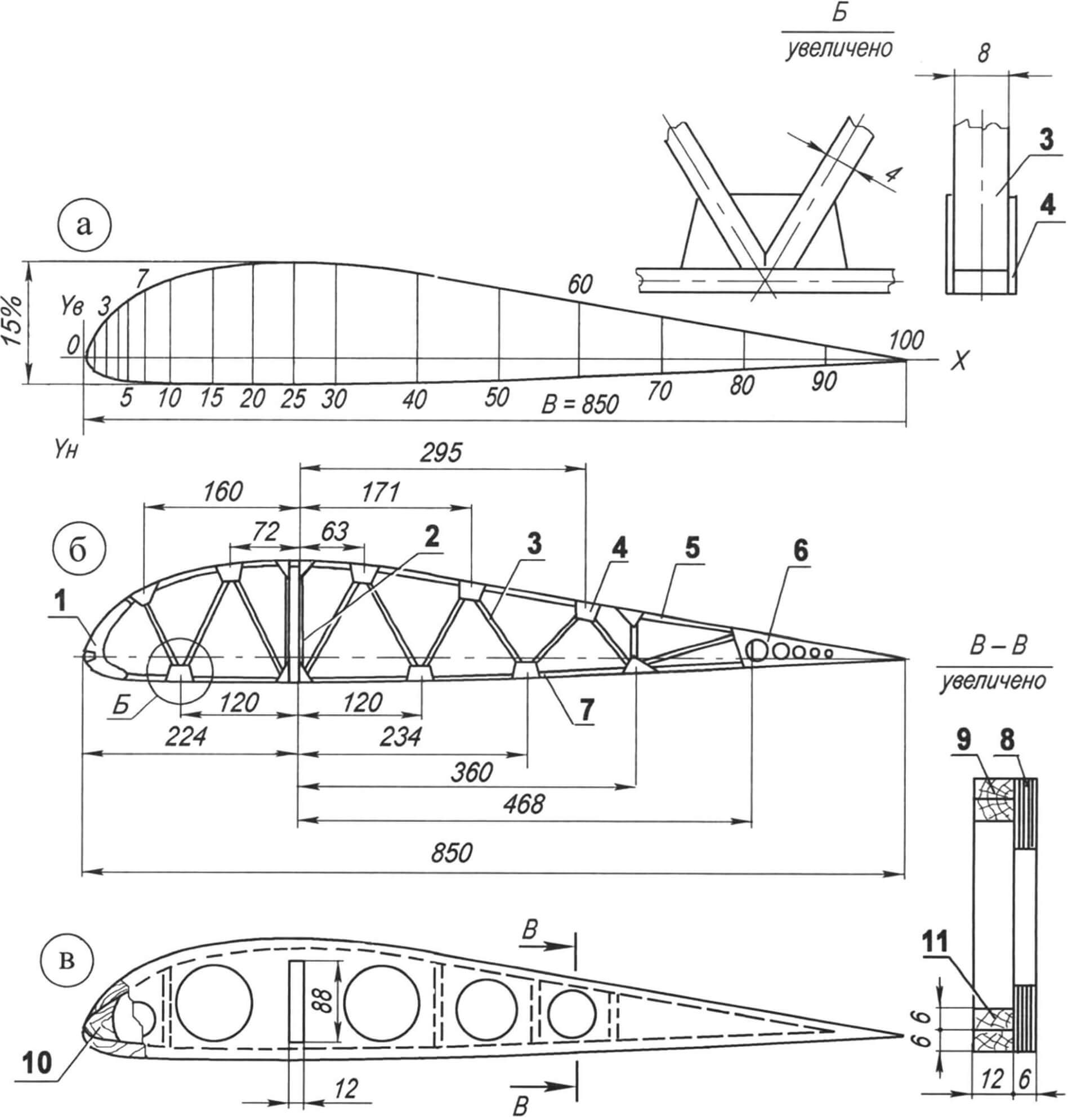
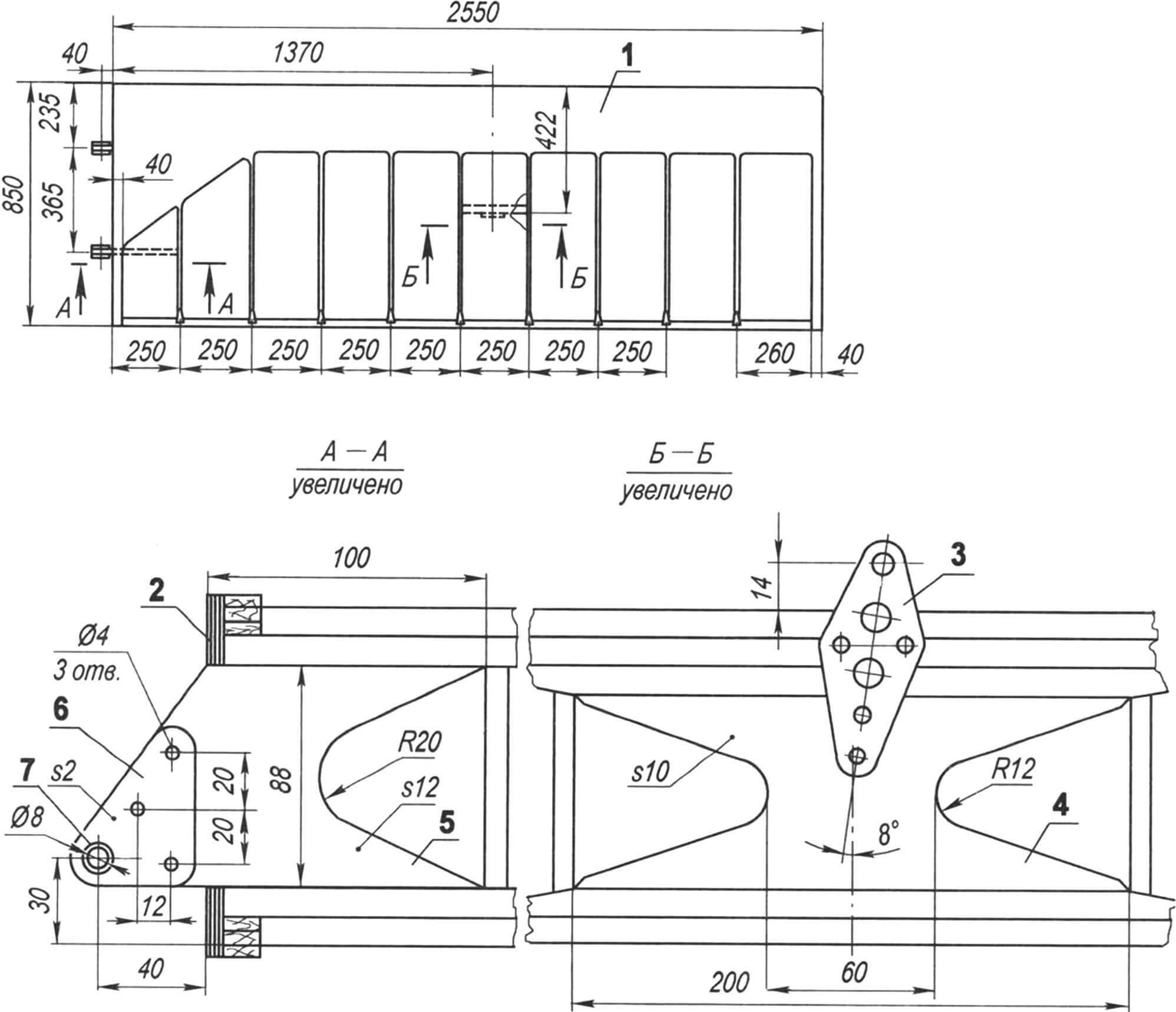
Wings and plumage. According to its design, as already noted, the aircraft is a single-strut biplane (actually there are two struts – between the upper and lower half-wings on both the right and left sides). The racks are V-shaped, the front branch is made of an oval-section duralumin pipe, the rear one is made of a round pipe.
The wings, both upper and lower, are single-spar; they have the same biconvex PIPA profile with a relative thickness of 18%. This profile, developed at TsAGI in the early 1930s, is still widely used today, as it has high load-bearing characteristics. Technologically, the wings are divided into left and right detachable parts.
1 — spout trim (plywood s1); 2 — spar; 3 — covering the plane (percale impregnated with enamel); 4 — rib; 5 — fairing for aileron control cable wiring (4 pcs.); 6 — incomplete rib; 7 — ending; 8 — aileron nose trim (plywood s1); 9 — aileron mounting bracket (2 pcs.); 10 — aileron cover (percale impregnated with enamel); 11 — end rib of the aileron (root—mirrored); 12 — oblique rib of the aileron; 13 — trailing edge of the aileron; 14 — aileron bracket; 15 — trailing edge of the wing; 16 — wing book; 17 — root rib; 18 — attachment point for the half-wing to the pylon bracket (2 pcs.); 19 — bracket for fastening the interwing strut; 20 — “wall” — additional spar; 21 — aileron spar; 22 — aileron control rocker; 23 — aileron swing axis (2 pcs.); 24 — visor; 25 — aileron control wiring (cable Ø1.5, 2 pcs.)
1 — central post (pipe Ø60×2); 2 — plate for attaching the pylon to the main post (sheet s4, 2 pcs.); 3 — front strut mounting bracket (stainless steel, sheet s2.5); 4 — radius washers; 5 — aileron rocker; 6 — aileron rocker bracket; 7 — pylon (pipe Ø60×2); 8 — brackets for fastening the upper wing console (4 pcs.); 9 — fastening of brackets to power elements (M12 bolt, 2 pcs.); 10 — fastening of plates to power elements (M8 bolt, 3 pcs.)
1 — nose of the rib (pine strip of variable section); 2 — spar opening post (pine slats 8×4, 2 pcs.); 3 — strut (pine slats 8×4); 4 — bracket (plywood s1); 5 — upper arch of the rib (pine strip 8×4); 6 — end bracket (plywood s1); 7 — lower bow (pine slats 8×4); 8 — sidewall (plywood s6); 9 — upper bow (glued together from two 12×6 pine slats); 10 — nose of the root rib (pine liner of variable cross-section); 11 — lower bow (gluing together of two 12×6 pine slats)
The spar has a channel-shaped cross-section: the shelves are made of pine slats with a cross-section of 10×10 mm, and the wall is made of plywood 1 mm thick.
The ribs are assembled from pine slats with a cross-section of 8×4 mm. Each half-wing is assembled by threading ribs onto a spar.
| X,% | 0 | 0.5 | 1.0 | 2 | 3 | 5 | 7 | 10 | 15 | 20 | 25 | thirty | 40 | 50 | 60 | 70 | 80 | 90 | 100 |
| Yb,% | 0 | 1.98 | 28 | 4.16 | 5.24 | 6.98 | 8.34 | 9.87 | 11.41 | 12.02 | 12.16 | 11.92 | 10.56 | 9.05 | 7.28 | 5.46 | 3.64 | 1.82 | 0 |
| -Yн,% | 0 | -0.91 | -1.29 | -1.75 | -2.03 | -2.35 | -2.31 | -2.65 | -2.77 | -2.82 | -2.82 | -2.80 | -2.61 | -2.30 | -1.95 | -1.52 | -1.04 | -0.52 | 0 |
All wooden parts are joined using epoxy glue. The skin of the nose of the wing is made of 1 mm plywood – it, together with the spar, forms a closed loop and absorbs torque. The rest of the wing is covered with percale and covered with enamel. By the way, he also glued the percale sheathing to the wooden elements of the power set.
The upper wing, unlike the lower one, has ailerons and a slightly larger span. The ailerons have the same single-spar design as the wing. Only the ribs are arranged in a zigzag pattern, and the profile is symmetrical.
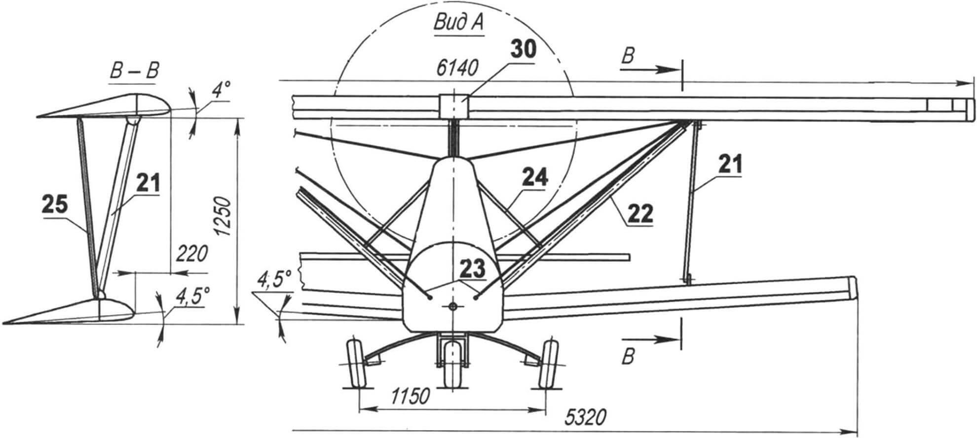
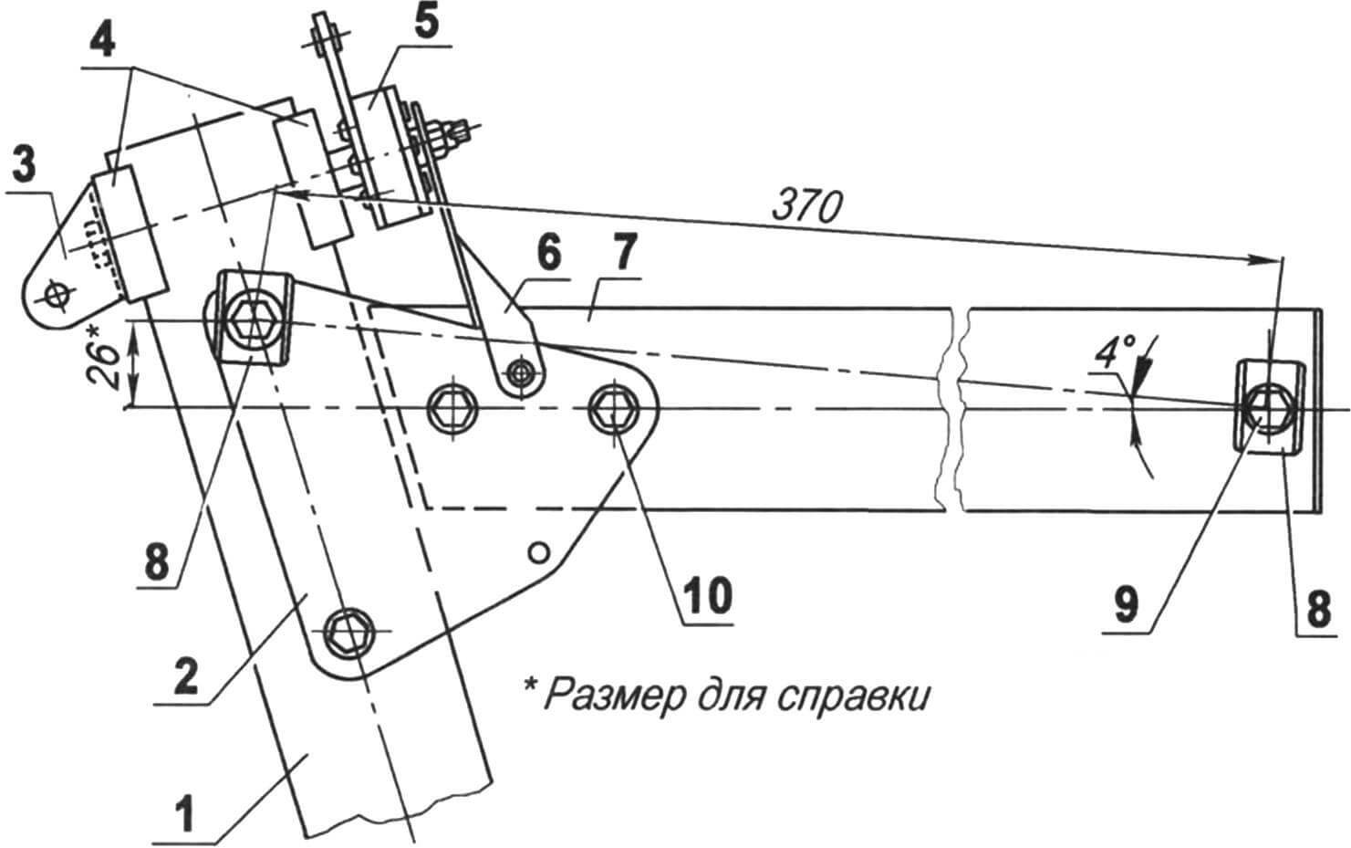
The upper wings with an installation angle of 4° are mounted on the pylon of the central pillar without a transverse V. The gap between them is closed with a duralumin cover. Additionally, each upper half-wing is attached to the main beam of the truss with a strut and a cable brace.
1 – sheathing (plywood s1); 2 — root rib (s6 plywood); 3 — rack bracket (stainless steel s2); 4 — bracket boss (plywood, s10); 5 — boss of the half-wing attachment point (plywood s12, 2 pcs.); 6 — trim (duralumin s2, 4 pcs.); 7 — bushing (tube Ø8×0.5, 2 pcs.)
The lower half-wings are docked to the main beam of the truss with a transverse V = 4.5°. The installation angle of the lower wing is also 4.5°.
The horizontal tail (HT) consists of a stabilizer and an elevator.
The vertical tail (VT) includes the fin and rudder (RN). The steering wheel is one-piece with a knife that is deflected on the ground. The fin and stabilizer are connected to each other by brackets and struts, and the upper ends of the struts with the wing struts are connected by cable braces.
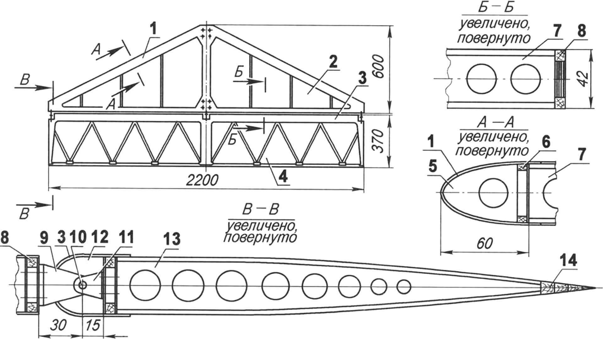
1 — trim of the stabilizer spout (plywood s1); 2 — stabilizer cover (percale); 3 — trim of the elevator nose; 4 — covering the elevator (percale); 5 — front part of the stabilizer rib (plywood s1); 6 — stabilizer spar; 7 — stabilizer rib; 8 — stabilizer wall; 9 — stabilizer hinge bracket (2 pcs.); 10 — hinge axis of the elevator suspension (3 pcs.); 11—elevator suspension bracket (2 pcs.); 12 — front part of the elevator rib; 13 — rib of the elevator; 14 — trailing edge of the elevator
The force set of the fin and stabilizer is similar to that used in the wings, and the rudders and elevators are similar to those used in ailerons with a zigzag arrangement of ribs. The profile of all tail elements is symmetrical to TsAGI-683. The toe casing is made of millimeter-thick plywood, and behind the spar is linen (percale). The coating is also enamel.
Power point
First, the aircraft was equipped with a two-cylinder RMZ-640 engine with a power of 32 hp. from the Buran snowmobile and a two-bladed pusher monoblock propeller with a diameter of 1600 mm of constant pitch. And with this setup, the plane flew well and handled confidently for many years. But one day I found out that a Rotax 582 two-stroke liquid-cooled engine was being sold at a relatively inexpensive price. It turned out that the engine was disassembled: the owners wanted to repair it, but then they could not reassemble it. So I bought it in bulk, and then assembled it, eliminating the faults along the way.
1 – keel; 2 — rudder; 3 — rocking chair (D16, sheet s3); 4 — bracket for attaching the keel to the stabilizer (4 pcs.); 5 — rudder hinge (2 pcs.); 6 — hinge ear of the rudder (duralumin, sheet s3, 2 pcs.); 7 — rudder hinge eye (stainless steel, sheet s1, 2 pcs.); 8 — bushing (stainless steel, pipe Ø6×0.5, 2 pcs.); 9 — bracket for fastening the brace (2 pcs.)
In terms of dimensions, weight, volume of two cylinders, the Rotax is approximately the same as the RMZ-640, but its power is almost twice as high (there is even a version that the second engine is not an entirely successful copy of the first). In addition, Rotax has a dual-circuit ignition system (two spark plugs per cylinder) and liquid cooling of the cylinders. The fuel is not in short supply – motor gasoline AI-95 mixed with motor oil in a ratio of 50:1.
And if when replacing engines it was almost not necessary to redo the fastening units, then the propeller had to be purchased: a new one: with a diameter of 1680 mm, also pushing, but three-bladed, pitch adjustable on the ground. A reduction gearbox with a gear ratio of 3.47 is combined with the engine and provides the propeller with up to 1900 rpm.
1 — fork stand; 2 — upper cross member of the fork; 3 — rubber band drum (pipe Ø10×1, 2 pcs.); 4 — rubber band roller (circle 8, 2 pcs.); 5 — bushing for the support column axis (pipe Ø12×2, 2 pcs.); 6 — shock absorber (rubber cord Ø8, 4 pcs.); 7 — lower cross member of the fork; 8 — cross member of a double-arm lever (pipe Ø20×2); 9 — bandage (nylon threads); 10 — axle eye (steel sheet s2, 4 pcs.); 11 — rack reinforcement (2 pcs.); 12 — eye bolt for fastening control wiring (2 pcs.); 13 — stop (rubber, 2 pcs.); 14 — fastening the stop (M4 bolt, 2 pcs.); 15 — upper knee of a double-arm lever (2 pcs.); 16 — scarf (steel sheet s2, 4 pcs.); 17 — lower knee of the double-arm lever (2 pcs.); 18 — wheel axle bushing (2 pcs.); 19 — double-arm lever axis (Ø8 roller with washer and cotter pin, 2 sets); 20 — bushing for the axis of the double-arm lever (2 pcs.); 21 – rack axis
With the new propeller-engine installation, the aircraft acquired higher flight characteristics and became capable of performing quite complex aerobatic maneuvers.
The fuel reserve is small – only 20 liters: after all, the plane is designed for training flights near the airfield, but this fuel lasts for an hour and a half. Fuel is poured into an aluminum canister mounted on a platform behind the driver’s seat.
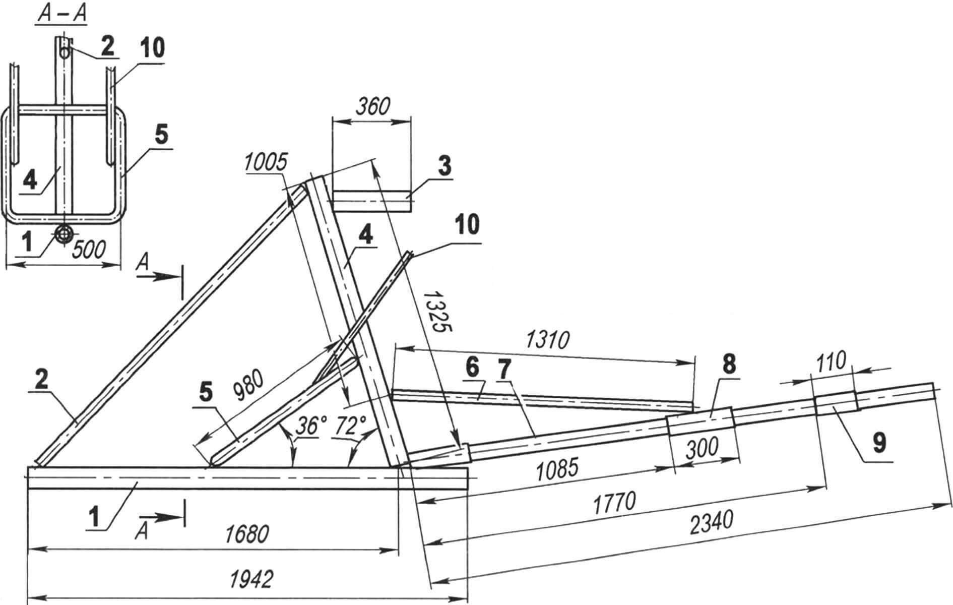
The aircraft’s landing gear is three-post with a steered front wheel. Shock absorption is carried out by a rubber cord with a diameter of 8 mm, wound in a loop behind the pendulum crossbar. The ends of the cord are connected and secured to the upper transverse post.
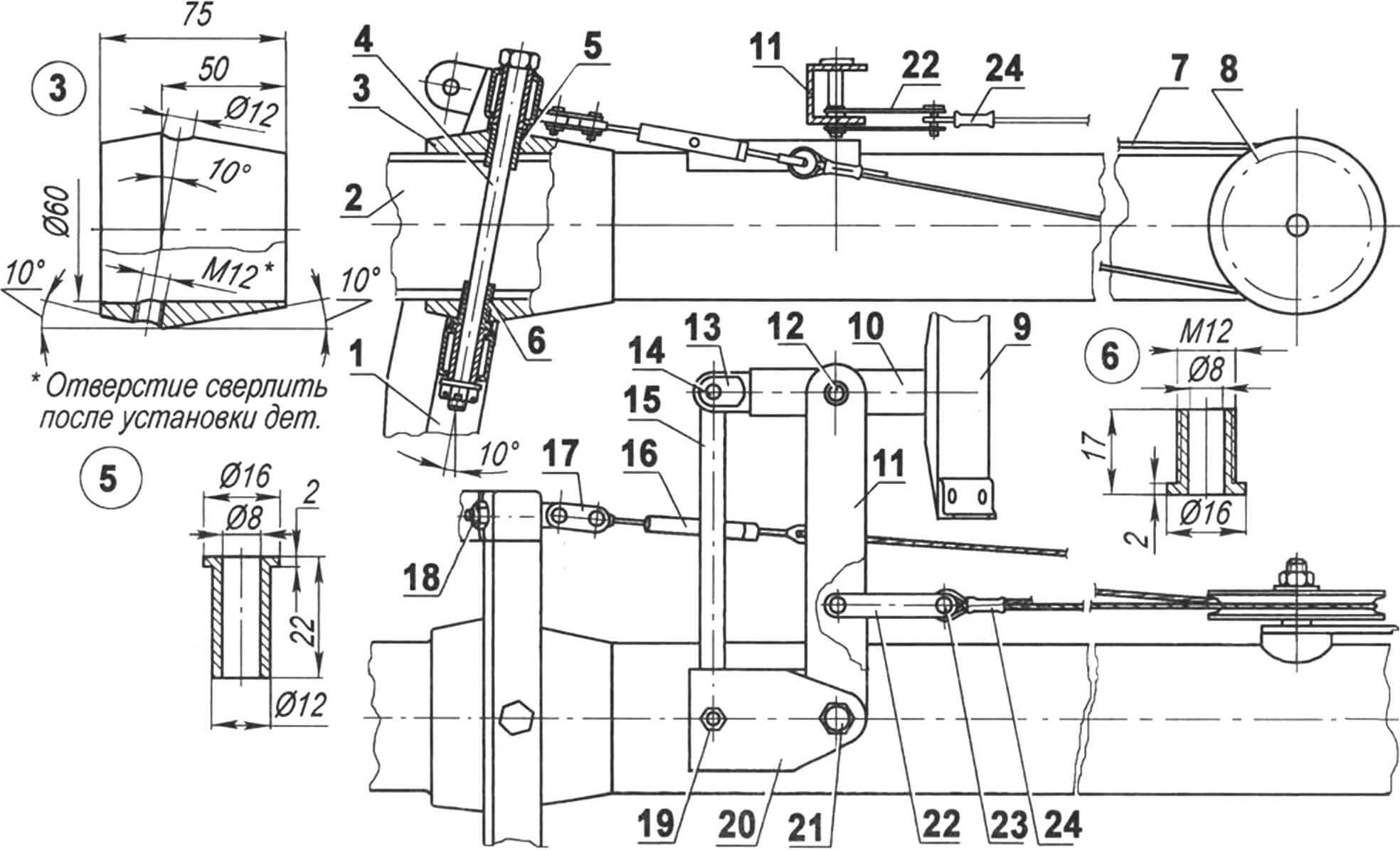
1 – stand; 2 – main beam; 3 — bougie (D16T, pipe Ø80×10); 4 — rack axis (M10 bolt with castle nut and washer); 5 — upper support sleeve (bronze); 6 — lower support sleeve (bronze); 7 — cable Ø1.8; 8 – roller; 9 — pedal; 10 – lever; 11 — rocking chair; 12 — axis of the lever and rocker; 13 — lever tip; 14 — axis of the tip of the lever and rod; 15 – traction; 16 — tander; 17 — stand earring; 18 — eye bolt; 19 — thrust axis; 20 — bracket for fastening the rod and rocker; 21 — rocking axis; 22 — rocking earring; 23 — roller with cotter pin (4 sets); 24 – cable termination
The front wheel is controlled by pedals through flexible (cable) wiring. The brake mechanism is also mounted on the same wheel, which is activated by a lever mounted on the aircraft control handle. The rear main support wheels are mounted on a transverse spring made of steel strip.
All wheels are the same, with an outer tire diameter of 280 mm and a width of 90 mm. They were used from the card. The rear wheel track is 1150 mm, and the wheelbase (the distance between the axles of the front and rear wheels) is 1520 mm.
To protect the tail boom from damage when it touches the ground, a heel is provided.
From the very beginning, the plane was conceived without a cockpit – only in this case can you fully experience the flight and feel the car. However, subsequently it was still equipped with a homemade fiberglass nose fairing with a bottom and a transparent visor of a 5-mm plexiglass sheet.
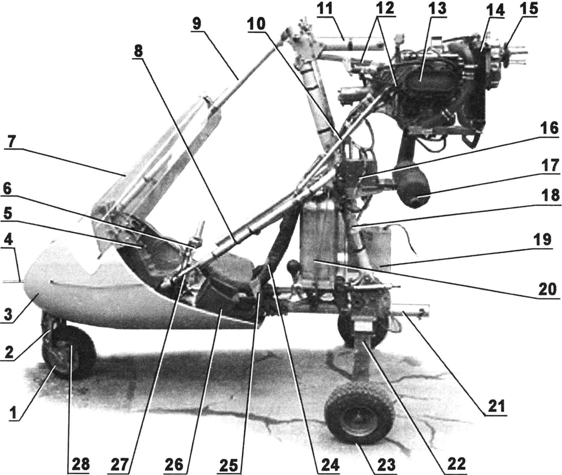
1 — front wheel (steered, braked, Ø280, b90, kart); 2 — front wheel stand; 3 — fairing (fiberglass); 4 — air pressure receiver; 5 — dashboard; 6 — aircraft control stick; 7 — windshield; 8 — seat frame; 9 — front strut; 10 — engine mount strut (duralumin pipe Ø16×1); 11 — pylon for attaching the upper wing; 12 — motor frame; 13 — Rotax 582 engine, N = 64 hp; 14 – radiator; 15 — propeller shaft; 16 — electronic unit; 17 — muffler; 18 — central pillar; 19 — battery; 20 — fuel tank V = 20 l (aluminum canister); 21 — tail boom; 22 — spring of the main wheels; 23 — main wheel (Ø280, b90, from card, 2 pcs.); 24 — seat; 25 — seat belts (car); 26 — tool box; 27 — engine control lever; 28 – brake mechanism
The seat is also homemade. Its basis is nylon belts sewn to an inclined frame, which serves as an additional brace for the central pillar. The base is covered with a foam cushion and back, covered with thick fabric – avisent. Seat belts are car seat belts.
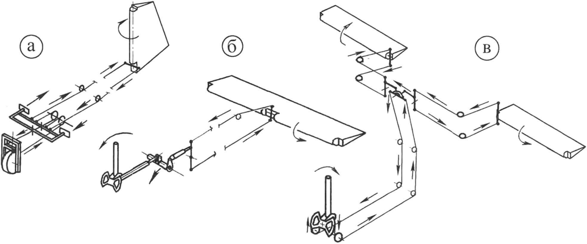
The aircraft control system is a cable system with intermediate rods from the control stick (RUS), located on the farm in front of the pilot. The engine is controlled by a lever mounted to the left of the pilot. Deflection of the rudder and rotation of the front wheel while taxiing is done using pedals. The aircraft is equipped with the necessary instruments to ensure flight in simple meteorological conditions (SMC) and control engine operation. All of them are located on the instrument panel in front of the pilot. There are headlights on the upper wing, and navigation lights on the tail.
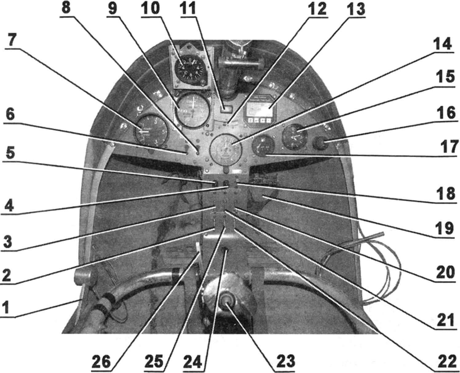
1 — engine control lever; 2 — toggle switch for turning on headlights; 3 — gas station of generator 1; 4 — generator 2 failure lamp; 5 — generator 1 failure lamp; 6 — ignition switch of the 1st circuit; 7 — variometer (ascent and descent speed indicator); 8 — ignition switch of the 2nd circuit; 9 — horizontal speed indicator; 10 — accelerometer; 11 – warning lamp for engine malfunctions; 12 — slip indicator; 13 – integrated engine operation monitoring device; 14 — altimeter; 15 — hours; 16 — cigarette lighter socket; 17 — fuel indicator; 18 — power switch; 19 — rudder and front wheel control pedals (2 pcs.); 20 – gas station starter; 21 — gas station of generator 2; 22 — toggle switch for turning on the beacon and signal lights; 23 — aircraft control stick; 24 — engine start button; 25 — toggle switch for turning on instrument lighting; 26 — brake lever
As for the flight characteristics of the aircraft, some of them are shown in the table, while others, such as the speed lifting, the maximum flight height, have not yet been measured.
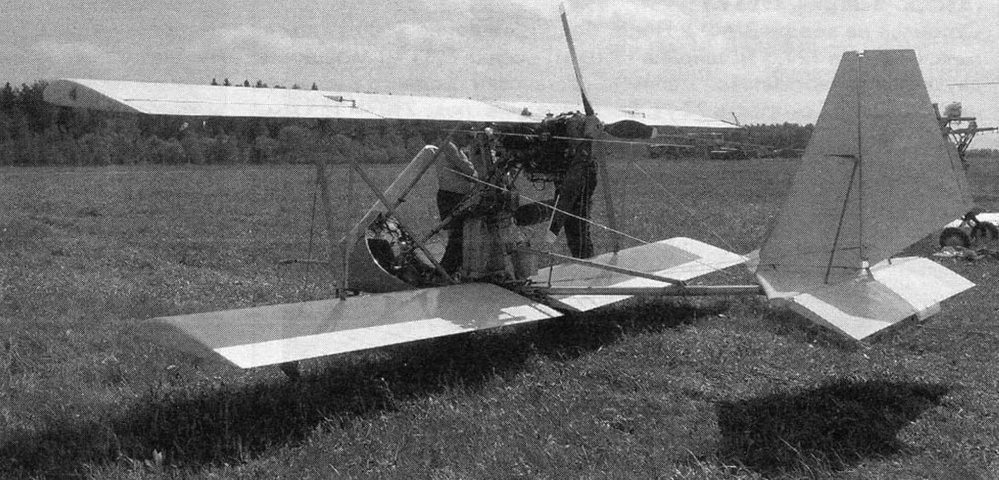
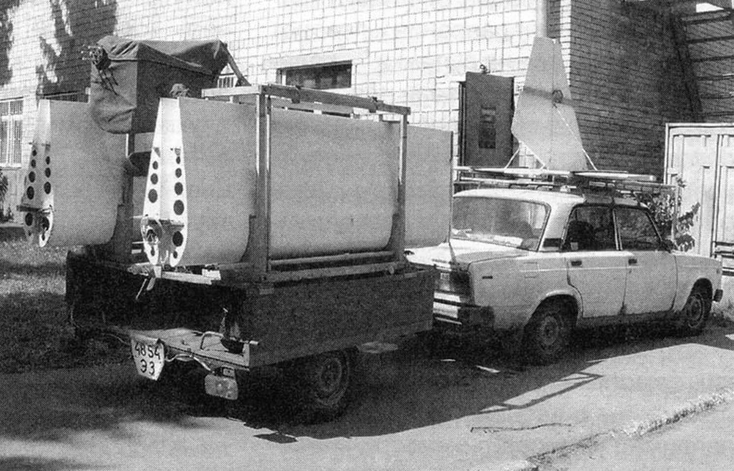
A considerable advantage of the design is that it is collapsible. For transportation (or storage), the plane is understood into several parts: half -wings, tail beam are disconnected from the aeromodul, and the plumage from it. The tail is transported on the roof trunk of the car, and the remaining parts in a two -wheeled trailer for a passenger car, fixed on a special platform. The design is stored along with a trailer in a regular automobile garage, and is assembled in the field in less than an hour by one person.
The characteristics of the aircraft
Length, mm 4570
Height, mm 1970
Wing:
upper/bottom scope, mm 6140/5320
Upper/Lower area, m2 5.11/4.43
Chord, mm 850
Lengthening 6.98/6.23
Eleron’s scope, mm 1440
Horda Eleron, mm 260
Eleronov Square, m2 2 × 0.37
Elerons deviation angles, hail +23/-18
Scope GO, mm 2200
Square GO, m2 1.54
The angle of installation GO, hail -1.5
RV area, m2 0.77
RV deviation angles, hail +30/-25
Square V, m2 0.88
Square pH, m2 0.47
Deviation angles pH, hail ± 30
Rulet mass, kg 270
Fuel mass, kg 16
Message of the structure, kg 180
Speed (according to the device), km/h
Maximum 150
cruising 90
Rulet 60
dumping 55
Rotax 582 engine
Power, L.S 64
The number of revolutions per minute 6500
Fuel AI-95 gasoline in a mixture with oil 50: 1
Screw diameter, mm 1680
Screw step, mm 700
From the editor
The editors warns that flights on homemade la are allowed only if there is an appropriate certificate and pilot certificate.
Recommend to read
 WARDROBE WITH… POTATOES
In our area, where most of the year is negative or close to zero temperature, it is foolish not taken advantage of the free cold storage of vegetables, fruit, roots. It would be nice.... GERMAN GRANDPA “ABRAMS” AND “LEOPARD – 2”
In the summer of 1963, the Ministers of defense of the United States and Germany - Robert McNamara and William Hassel had signed a bilateral agreement on joint development of a new main...
