
 When vehicle type is defined: scheduled its approximate dimensions, weight, number of seats in the back, the engine, comes perhaps the most important stage of design development of the layout. Layout is the overall structure, and relative position of all parts of the structure. It would seem that a depot purely technical: linking dimensions, calculation of loads and so on. But no, it starts not with the mechanisms and numbers.
AROUND THE PERSON
Every car should be designed for use by people of different height and build.
However, only a mechanical adherence to this principle would lead to an increase in the size and weight of the car — it would have to take into account the tallest! So focus on the figure of a man of average height — 172 cm, and for other drivers provide design adjustment of certain dimensions: the distance from the driver’s seat back to the pedals within ±60 mm to the controls ±50 mm, etc. From the seat cushion to the ceiling and between the backrests front and rear seats (pitch) distance is chosen based on high human growth 182 cm, that is, respectively, about 1000 and 680 mm.
Sometimes Express the wish that the driver can change position to relax and prevent swelling of the body. This wish contradicts the efforts to establish a comfortable working posture of the driver. Obviously (and this is recognized by many designers and reputable firms) that the seat should provide a specific geometry of the working postures and the lowest specific pressure on the body of the driver, the pressure should be redistributed in the most minor movements of the body. Then there will be swelling!
This meets the requirements of semi-rigid seat body fitted person. This seat, called anatomic, which we will focus in the future, is a “Cup” made of metal or plastic, coated with a layer of elastic sponge material with the thickness of 30— 50 mm.
Therefore, you first need to make templates like this “bowl” and “the middle man” and start the layout of the car with the definition of the seats. If it is too low, the driver is forced to lift his head, straining the muscles of the neck and back. Conversely, if the seat is too tall he has to stoop, to bend the head. In this case, the easily fatigued muscles of the shoulder girdle, eyes, shrink the stomach and lungs, difficulty breathing. In both cases, it is inconvenient to operate the pedals. To traffic the driver was fast and accurate way, which make the hand or foot actuating the levers or pedals must be the smallest. You need to the body and thighs of the driver relied on the seat throughout their length. If to lower the height of the vehicle it is necessary to reduce the height of the seat, shall be equipped with the its tilt, which make the smaller, the higher is the steering wheel, and the larger the angle of inclination of the steering column to the horizon.
The sizes and technical requirements to the workplace of the driver (of the truck) in the Soviet Union there is a standard 9734-61 that can be used when building a homemade car.
Non-compliance with GOST leads to tragic results. For example, close to the shield of the instrument arm can cause hand injury.
Very important to adjust the distance from pedals to seat back. More often there are cars installed with a fixed seat and adjustable pedals. Install pedals on a sliding or swinging bridge under the shield of the instrument makes it possible to comfortably accommodate the driver and to reduce the length of the car.
Good visibility of the road from the driver’s seat is one of the most important in terms of ease of driving and the safety of its movement. It depends on the seat position, the size and shape of Windows, design of pillars, shape of the hood and fenders of the car.
The improvement is achieved: the increase in seats and reduction of its inclination; by bringing it closer to the front end of the car; increase the windscreen and other Windows; the decrease in tilt angle of the glass and bringing it closer to the driver eyes; to reduce the thickness of the uprights and setback. To implement all these measures it is not always possible. Therefore, the designer must find a compromise.
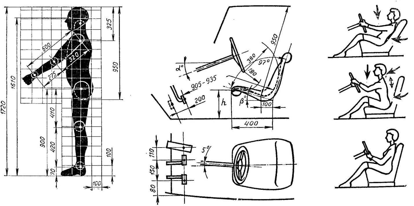
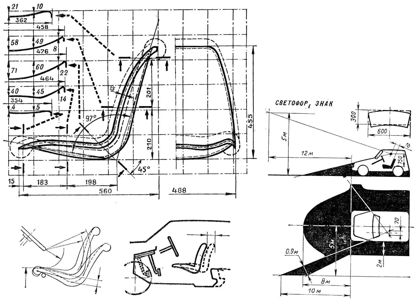
In the top row — the pattern of the figure “average person.” The recommended size of the driver’s seat and panel sizes (“Cup”). Examples of uncomfortable, too low landing of the driver. The arrows show the tense parts of the body. The third scheme is a normal fit. Left — panel sizes (“Cup”) anatomical seat. The dashed line shows pocrisy (mattress) of the seat. Thin straight lines are given for the orientation angles. The grid sizes 100×100. In the bottom row — you can adjust the multicontour seat change in its slope. Adjustment of the pedals instead of moving the seat allows you to shorten the body. The third scheme — the maximum allowable dimensions invisible to the driver side of the road. Top right — size clean wiper glass area.
Guest are some simplified scheme of evaluation of visibility, shown permitted the “blind zone”, closed from the driver of the vehicle housing. To ensure that they have not built a car to the requirements of GOST, it is necessary to depict in the drawing, the projection stands and the front of the car to the road surface, making lines from “point of view” of the driver — it is marked on the template of the man through the points of the contours of the Windows and front.
All of the above on the driver’s seat applies to the passenger seats. The constructor does not make mistakes, if unify their design. Of course, the passenger seat does not need adjustment, can be fitted with several large slope.
It is appropriate to again address the issue of seat stiffness. It may seem that the above anatomical seat isn’t that comfortable. Calculations and practice show the opposite. Soft spring or foam rubber or shaking the seat cradles the rider to sit on it hot, it takes a lot, thereby reducing the useful height and length of the body. Therefore, we will continue to focus on anatomical seat.
LAYOUT DESIGN OF THE CAR
So, proceed to the layout. Her drawing is performed in the scale 1:5. In preparation for this work, we draw on cardboard or, better, on celluloid the contours of the lateral projections of the seats, powertrain, wheels, battery, fuel tank, cut them out and “fold” side of the car. To check comfort fit use pattern figures of a man in the same scale. Transfer the resulting layout for the next drawing and execute the corresponding other projections (plan, front view), at the same time producing the necessary clarifications.
The height of the floor level from the road surface should be as small as possible for reasons of stability, smoothness and aerodynamics of the car. In the drawing, draw the line of the floor parallel to the road surface at a distance equal to the value of the ground clearance not less than 150 mm plus the thickness of the floor (sheet metal, plywood or boards). If the vehicle has a frame, the floor is installed on top of it or is advanced between the bars.
Specifying the size of the body and its height position, the intended pre-designated front and rear axles. Subsequently, they can be modified when updating the design of the transmission, suspension, steering gear.
If the car is rear-engined, which often build Amateur designers, the axis of the front wheels should be placed as close as possible to the driver’s seat to shift forward the center of gravity of the vehicle. Distance from the front edge of the seat to the front contour of the door opening should be about 200 mm. Thus the longitudinal distance from the seat to the front axle consists of a wheel radius (300 mm) plus the gap between the wheel and the housing around 50, plus a body structure between a casing and a door — 50-100 lumen — 200, only about 600 mm. While foot floor will be very close to the front axle and will require an appropriate device and location of the front suspension and steering rods. Most fit suspension with transverse leaf springs or directed from the wheels forward suspension arms and transverse torsion bars, as in “Zaporozhets”; tie rod located either in front of the axle or above it.
It is necessary that the width of the body between the housings of the front wheels was not less than 700 mm, which is sufficient for the placement of the pedals and feet of the driver and passenger. Distance from the inner wall of the housing to the longitudinal plane of symmetry of the wheel (including the outer radius of the tire of not more than 300 mm, the width of its profile 130-140 mm, rotating the wheel about 30 degrees and the gap between the rotated wheel and the casing 20-30 mm) should be no more than 200 mm. Thus, the track must be equal to not less than 1100 mm.
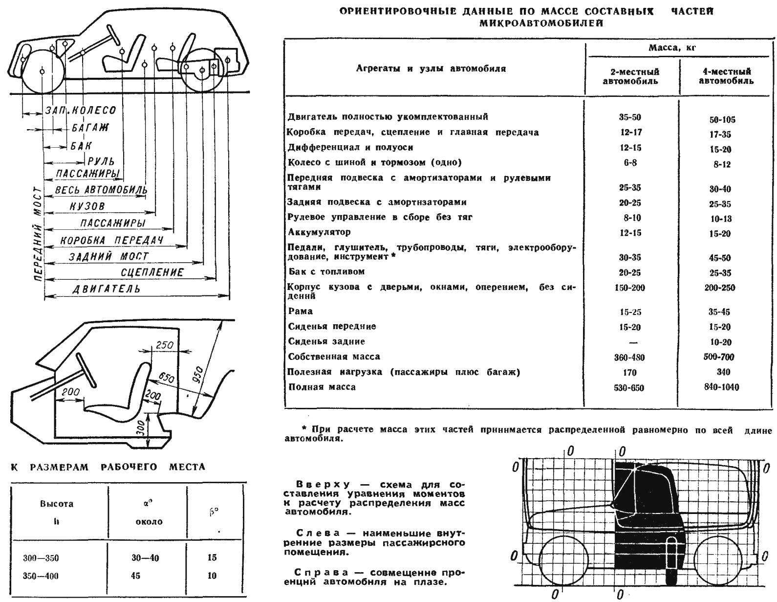
The figure shows the recommended dimensions of the passenger area of the body. The driver’s seat shown in the middle position.
Space for Luggage under the front hood, behind the rear seat backrest or in the back of the body is calculated for 10 kg (medium size suitcase) for each passenger, that is 0,1—0,2 m3 have a double car and of 0.2—0.4 m3 for quadruple.
The length of the wheelbase for vehicles of this class, as we know from the experience of 1,500 to 2,000 mm. the Latter quantity is sufficient for four cars. The final choice of database size depends largely on the distribution of mass on the wheels. For reasons of vehicle stability and loads on the tires is not desirable that the rear wheels had more than 60% of the total mass of the vehicle. Knowing at least approximately the mass of the individual parts of the car are so-called equation of moments and find the centre of gravity position:
GAxLA = GaxLa + GzxL, z + G, pxL, p…
Here the letter “G” means the mass in kg and L is the distance from the baseline (e.g., the front axle or front buffer) to the center of gravity of the car or its parts. The indices mean: a — car, d — jet, z — axle rear, W — front axle, R — management bodies, etc.
The table below gives the approximate values of the masses of car parts. The figure shows a scheme for the compilation of the equations; all dimensions except the distance La from the baseline to the center of gravity of the vehicle, is known from a preliminary layout of the vehicle, the mass of the parts from the table or based on a weighing of finished parts. The equation has only one unknown that is easy to find, and then find out what part of the wheel base is distance from front axle to center of gravity (in %). You can say that a satisfactory result will probably be obtained only when the location of the tank, spare wheel, battery and tool in the area of the front wheels (under the “hood”), In the case of unsatisfactory results, it is necessary either to extend the base, or move the individual elements of the car as far as possible forward, as was done, for example, on the newest cars rear-engined Czechoslovakian Skoda and Tatra. It would be easiest, as we already know, to place the engine ahead of the rear axle, but then not be able to use a significant portion of the body, worse access to the engine.
We have already noted that the builders of home-made cars often use the so-called “wagon” layout. It is necessary to consider some of its features.
The two-seater is advantageous to compose the scheme of the famous “Isetta”, that is, taking the length of the base is about 1600 mm, install the seat front edge close to the housings of the front wheels, and the motor ahead of the rear axle. When removal of the power unit behind the rear axle it makes more sense to make the car four or under the scheme “2 + 2” (two children’s). The best distribution of mass is achieved when installing the seat between or above the front wheel housings, which, however, is not without difficulties: it is necessary to increase either the gauge and width of the body between the enclosures or the height of the car. A possible way out of this situation — the use of anatomical features of the seat when the side parts are raised above the shrouds, and the average is lowered between them. Suspension would be located under the floor or seat.
After a preliminary layout of the car begin to develop powertrain and suspension, to clarify the position of the engine, to check the adequacy of road gaps, make necessary adjustments to the layout.
Drawing layout should be provided coordinate grid. It facilitates and clarifies the linkage of dimensions and consequently you will need to design the shape of the body. For zero Pigna starting taking the projection on drawing: dimensions for the longitudinal — vertical plane passing through the axis of the front wheels, to a transverse plane of symmetry of the vehicle, the altitude and the main plane of the floor of the body. In all directions at distances that are multiples of 200 mm (or 100) in nature, draw lines parallel to zero. Around lines put the numbers. Very important is the accuracy of the grid. Diagonal taken from her any of the rectangle should not differ by more than 0.5 mm. Have professional designers even 0.25 mm. Suggest designers to immediately “lay” and plazovy drawing of the car in life-size on a roll of paper, dense cardboard or better plywood, to reduce the size of the projection of the combine. At Plaza convenient to Refine the layout, linking the dimensions.
The linker helps a prototyping vehicle with the use of such simple materials as plywood, cardboard, clay, wooden planks.
Wheel housings shall be designed for the displacement of the wheel and its rotation, plus the gap of 20-30 mm across the surface of the casing.
In General, when the layout of the micro-car, only need to strive for maximum use of space, then machine work is relatively small, spacious and light.
Recommend to read
 The Yak-18
Initial training aircraft Yak-18 was based on UT-2. Its first flight took place on may 6, 1946 (test pilot G. S. Klimushkin), and the second, with the more powerful M-11FR — may 17,... TRACTOR
At school, for more than 40 years, engaged in the construction of various mechanisms to facilitate workplace and at home. (In the journal "Inventor and rationalizer" was placed in my...
