CATAMARAN FOR FOUR

CATAMARAN FOR FOUR

For water hikes inflatable catamaran has a number of advantages over the kayak. It is high reliability, great stability, with satisfactory maneuverability, increased permeability of the rapids sections, low weight, comfort, and convenience for boarding and alighting. In the end, the benefits outweigh the known disadvantages of a catamaran — high windage hull with the crew and low speed when driving on the oars. Propose a simple design of a catamaran, which used available materials.

Floats of a catamaran have a chamber structure, that is composed of outer shell for durability, and the inner chamber, ensuring tightness. This simplifies manufacture and increases reliability. The contours of the floats allow you to attain a low water resistance. The frame is assembled from dural pipes with bolted connections by shaped nuts. In some cases, the bridge catamaran (except stringers) can be connected from the trunks of small trees (with a diameter of 80-120 mm), which will reduce its mass in a disassembled state. The catamaran has a steering wheel that greatly facilitates management and allows you to alternately relax the rowers on the go (the catamaran is able to move at the rate even when the rowers on one side). The design of the catamaran you have the option of sailing arms. Almost all parts are made at home, it requires only a small amount of lathe work. The cost of the catamaran is low.
Describe the catamaran used on the plains, on the rapids of the rivers as well as lakes. On calm water it provides enough high-speed (25-30 miles per day), able to overcome the threshold of the third category of complexity, easily operated and not salesthese water with waves up to three points.
 
The theoretical contours of the float.
 
Open your camera without seam.
 
Cutting the upper n lower parts of the outer shell of the float
 
The technical characteristics of a catamaran
The size of float (mm)
 
FLOATS. Two of them, each one is an air-filled hollow, round in cross section design.
 
The float has almost no cylindrical section and you’ll be developed stern and bow sections. This ensures optimum distribution of the displacement length required to reduce wave drag. Large ratio of surface to underwater volume in the bow and stern of the float contributes to good germination on the wave. The point of application of Archimedes force is shifted aft and is in the middle between the theoretical frames 5 and 6.
 
The float consists of an outer shell and an internal airtight chamber (cylinder). Shell sizes 10-15 percent smaller than the camera. This is to ensure that the camera was in a relaxed state. Despite such a design, the floats have high security. In the formation of the small camera holes the catamaran retains buoyancy and may continue to move in periodic pumping of the floats on the go.
 
Camera made of lightweight rubberized material for nylon-based fabrics “Rain” (“silverfish”). Luggage synthetic material more durable and reliable, and from “silverfish” is cheaper, although its lifetime is limited to four to five seasons. Manufacturer of cameras — main operation, it takes the most time. Cutting are shown in Fig. If you can not find the camera from a single piece of cloth, piece of cloth of the required size, glued from pieces overlap. Joint width is 3 cm, and they are additionally glued strips of fabric.
 
The overlapping is performed and the longitudinal bottom seam. Glued it from the middle to both sides, and also enhanced tape. Particularly careful attention should be paid to the nose part: glue joints here is a short (50-100 mm) with cut-out wedges to prevent wrinkles. The rear extremity of the chamber is a sleeve, which in the Assembly is twisted and tied off with a rubber tourniquet. Bag design allows you to turn the chamber for drying and repair.
 
General view of the catamaran (on the main view of the right float and the deck is not shown): 1 — float; 2 — pocket stringer; W bow-slot; 4 — slot feed; 5 — valve; 6 -part of the stringer, and bow (coarse 32x2, L1950); 7 of the stringer feed (pipe 32x2, L1850); 8 — first beam, bow, cross (tube 45x1,6, L1750); 9 the second beam, transverse (rough 45x1,5, L1800); 10— the third beam, transverse (pipe 50x2,5, L1950); 11 — a beam of a fourth, aft, transverse (rough 45x1,5, L1750); 12 — longitudinal beam (tube 50x2,5, L1950); 13 -cosina (rough 32x2, 1080 mm); 14-wheel; 15 deck; 16 — lace-up deck
General view of the catamaran (on the main view of the right float and the deck is not shown):
 
1 — float; 2 — pocket stringer; W bow-slot; 4 — slot feed; 5 — valve; 6 -part of the stringer, and bow (coarse 32×2, L1950); 7 of the stringer feed (pipe 32×2, L1850); 8 — first beam, bow, cross (tube 45×1,6, L1750); 9 the second beam, transverse (rough 45×1,5, L1800); 10— beam, the third cross (tube 50×2,5, L1950); 11 — a beam of a fourth, aft, transverse (rough 45×1,5, L1750); 12 — longitudinal beam (tube 50×2,5, L1950); 13 -cosina (rough 32×2, 1080 mm); 14-wheel; 15 deck; 16 — lace-up deck

 
The camera is glued a valve from rubber boats (sometimes on sale). It is easy to make and yourself out of plastic or aluminum on a lathe. The location of the nasal valve in front of the rowers allows you to swap when needed floats to go.
 
The outer shell is sewn from crisp nylon (top) PVC material type to “thesis” (bottom) nylon thread with a seam of 10 mm. All seams are duplicated, and to the edge of the fabric is not “poured”, nylon cut out a soldering iron.
 
For attaching the floats to the bridge of the catamaran in their top pockets are sewn of nylon, in which are inserted the stringers. Pockets are not continuous, but in the form of loops of slings, the distance between them is 150-200 mm.
The upper part of the shell, if it cannot be cut out of a single piece of cloth, first sewn. Then it are two slits for insertion of the camera. The edges of the slit are reinforced by the strips of the same fabric with a width of 50 mm and installed eyelets for lacing. Two slits allow you to remove and insert the camera into the float without disassembling the catamaran for the repair of the campaign. Through the aft slot to the sleeve the camera snaps the rope, and the camera is pulled out through the nasal slit. This rope remains inside the shell, and the back camera is delayed. After that, sewn the pockets of the stringers. The bottom is also either cut out of a single piece of fabric, or from two panels. Next, sewn the top and bottom of the shell from the middle to the extremities. Cutting and assembling shell conducted as carefully as possible, with an accuracy of ±1 mm to ensure the correct shape of the float and to prevent wrinkles. While storing the camera in the upper shell longitudinal seam of the camera must coincide with the centerline of the shell.
 
Connecting the parts of the stringer
The connection of the parts of the stringer:
 
Part 1 – feeding; 2 — part of the nasal; 3 — textolite bushing; 4 – M5 bolt; 5 – nut M5.

 
Kreplenie the stringer to the bow and stern beams
Krepline the stringer to the bow and stern beams:
 
1 — sliding nut; 2 —stringer; 3 — sleeve (tube 28×2,5); 4 — nut M5; 5 cross-beam; 6 — M3 screw (2 PCs); 7 — rubber gasket; 8 — stud M5
 
Fastening the stringer to the middle beams
Mount the stringer to the middle beams:
 
1 – sliding nut; 2 – stringer; 3 – cross-beam; 4 – the hook (the stainless steel, rod d5).
 
Connecting the longitudinal beams of the first and second (a) third and (b) cross
The connection of the longitudinal beams of the first and second (a) third and (b) transverse:
 
1 – longitudinal beam; 2 — beam of the first or second, transverse; 3 – pin M8; 4 —M8 nut; 5 rubber strip; 6 — bushing (tube 50×2,5); 7 – M4 screw; 8 – beam, the third cross.

 
The attachment of the strut to the cross beam
The attachment of the strut to the transverse beam:
 
1 – cross-beam; 2 – cosina; 3 – stud M5: 4 — M5 nut; 5 – a lining rubber.

 
Paddle
Paddle:
 
1 — Valek (dural tube); 2 — cushion (foam); 3 — blade (aluminum, sheet s1,5): 4 — bolt M4 (4 PCs).

 
The BRIDGE of the CATAMARAN is made from a set of tubes (aluminum alloys D16, AMG, and the like) of different diameter and collected on the bolts or studs.
 
Each stringer consists of two parts connected by a sleeve of smaller diameter tubing or textolite rod. The sleeve is attached to the aft side of the stringer with glue and is fixed through a pin, the end of which raskladyvaetsya. The ends of stringers shall be closed with plugs of any material.
The stringers are fastened to the beams shaped nuts. Compound bow (first) and aft (four) beams to the stringers is enhanced by the sleeve of smaller diameter tubing. The second and third beams, the stringers, so as not to weaken them extra holes, fastened with hooks.
 
Cross beam are made of pipe of larger diameter. The third transverse and the third longitudinal beams are made more durable to increase the rigidity of the vessel and the possibility of installing of sailing arms. The third cross beam is elongated to facilitate the installation of cables. Stern (fourth) beam in the place of fastening of steering is enhanced by the sleeve of larger diameter pipe. Between the third and fourth beams are put strut for fixation in the horizontal plane. Strut attached to the joists also using pins.
 
The wheel
Steering wheel:
 
1 — rudder, 2 — plate (duralumin, sheet s3. 2); 3 — tiller (aluminum, pipe 25×2); 4 bracket (aluminum pipe 25×2); 5 — stretching (aluminum, pipe 22×2,2); 6 — axle (steel bar d5); 7 — axle beam, stern; 8 — strut axle; 9 — M12; 10 — M5 bolts (4 PCs.); 11,12,13,16 — M6 bolts (9 PCs.); 14 — loop cylindrical (steel, 3 pieces); 15 — loop flat (s2 steel, 3 PCs.)

 
Rudder
Rudder:
 
1 — plate (glass fiber); 2 -skeleton helm (tube 22×2); 3-rivet (d3, x4); 4 – screw M3 (4 PCs); 5 – M5 bolts; 6 harness (wire); 7 – sealer (clay): 8 – fill (epoxy resin).

 
The position of the mast
The position of the mast:
 
1 — mast; 2 – guy; 3 the forestay.
 
All hardware is here — of stainless or galvanized steel.
 
The position of the holes in the stringers and transverse beams is marked in the Assembly of the catamaran is fully inflated floats. The Assembly of the catamaran is conducted in the following sequence. First collected stringers are inserted into the pockets of the floats, and the latter inflates. Standing parallel to the floats overlap the bow and stern beams, they are marked and drilled for fixing to the stringers, then—through them — the holes in the stringers. After that, beams are attached to the stringers. In the same way, set the second and third transverse beams and finally the jib.
 
The DECK is a rectangular cloth of thick nylon. Its dimensions are specified on the assembled frame. The perimeter edge of the cloth folded three times width of 30 mm and is stitched, then installed eyelets for attaching the deck to the bridge. Lacing is conducted from the middle of the floats to the extremities. The deck also serves as a packing for catamaran during transport, so it is advisable to sew a lining of a dense material to prevent rubbing of the fabric tubes.
 
The wheel of the catamaran has the feather of sheet glass with a thickness of 2 mm. the Workpiece is split into two parts with a thickness of 1 mm. For this it is the angle of the incision in the middle to a depth of 10-20 mm, and further the glass carefully, without sudden jerks, it is torn with a pair of pliers. Then the two halves are folded together and front and rear edges of drilled holes with a diameter of 1 mm by about 50 mm. Then half are fastened through these holes, soft copper wire, and between them is inserted fully assembled frame made of pipes with a diameter of 22 mm. the Sheets of fiberglass are attached to the frame at the bottom of the rivets or screws and the upper screws with countersunk heads. After this edge the helm permanently crimped wire and sealed with clay. Each edge is filled with epoxy resin. Upon completion of the polymerization, the clay along with a wire is cut with a knife, and the edge sanded. The rudder can be made of two glass fibre laminate plates with a thickness of 1 mm, but in this case must be thoroughly sanded and degreased the surfaces.
 
The rudder is attached with a bolt between the plates of duralumin, thickness: 3 mm, These plates are connected with the tiller, made of pipes with a diameter of 25 mm, rivets, or screws. The rudder is hung on the bracket using improvised loops. The axis of the hinge — steel rod of 5 mm diameter, removing which is easy to remove the wheel. The steering bracket is a tube attached at the top to the middle of the feed beam, and at the bottom by means of two stretch — to yosina bridge. Holes in the stretch marks and Yoshino drilled in place during Assembly of the catamaran.
 
The PADDLES are made of duralumin tubes of suitable diameter for easy grip, and duralumin sheets with a thickness of 1,5 mm. At the place of attachment of the blade outrigger plusits in heated form, the blade is attached to the pipe by four rivets or bolts, the ends of which are carefully clench. In the opposite end of the tube is placed a plug of foam. To ensure the flooding of the paddle on it is glued to the cushion foam, the amount of which is determined empirically.
 
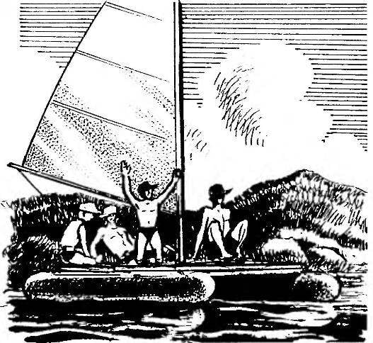
SAILING rig has an auxiliary character and often ineffective. Therefore, its description is not given here. However, the design of the bridge of the catamaran provides for the installation, the possible position of the mast, guys and stays shown. Alternatively, sailing arms recommended design, is used on the catamaran “Altair”, published in the journal “modelist-Konstruktor” No. 7 of ’83.
 
TROLLEY for transportation of the catamaran may have a different design depending on the available materials. The wheels for her — from children’s bikes that are comfortable on rough terrain.
K. BELEVICH, A. GORBACHEV, Nizhniy Novgorod

Recommend to read

  • GROVER ON THE HACKSAWGROVER ON THE HACKSAW
    On sale there is a very convenient universal handsaw — with a set of interchangeable paintings, having at one end a locking comb and a hole under the tightening bolt. But what is...
  • AND AGAIN, “THE MIRAGE”AND AGAIN, “THE MIRAGE”
    After publication in the "M-K", № 1, 1978 of the drawings trace model "Mirage" edition receives a lot of emails from guys who decided to build it. They are interested in some of the...