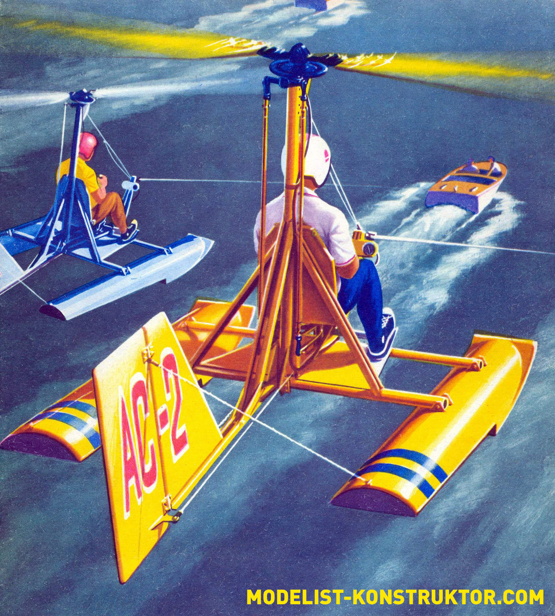
The non-motorized gyroplane “Chaika” was developed by students of the Riga Institute of Civil Aviation Engineers and is intended for initial training, sport flights and the promotion of aviation technical knowledge among a wide range of young people. The low cost of this machine, ease of piloting and maintenance, reliability and safety – all this allows us to hope that flights on non-motorized rotorcraft of this type can become the most popular form of aviation sport in our country. This is confirmed by the experience of a number of socialist countries, where flights on towed gyroplanes are very popular. The training course to manage them is carried out literally within a few hours!
Our magazine has already introduced readers to the design, construction technology and features of flights on non-motorized gyroplanes towed by a car or a motorboat (see No. 6 and 7 for 1969 and No. 3, 5, 6, 7, 10 for 1970). Therefore, we will not repeat ourselves, since the gyroplane of Riga students has no fundamental differences from the designs we described earlier. We present only a diagram of this machine in three projections, as well as a diagram of alignment and determination of the coordinates of the tow rope attachment point (material that has not been published anywhere before).
So, a brief technical description of the non-motorized gyroplane “Chaika”.
KEY FEATURES
| Overall dimensions (in mm): | |
| Rotor diameter | 6000 |
| Length with wheeled chassis | 3500 |
| Length with floats | 4020 |
| Height | 2120 |
| Weight characteristics (in kg): | |
| Structure weight | 65 |
| Flight weight. | 130 |
FLIGHT CHARACTERISTICS | |
| Lift-off speed | 35 km/h |
| Run length | 50 m |
| Towing speed range | 40—90 km/h |
| Minimum rate of descent | 4.2 m/sec |
| Power required for towing | 30-40 l. With. |
| Landing speed | 25 km/h |
According to the diagram, it is a wingless gyroplane with direct rotor control.
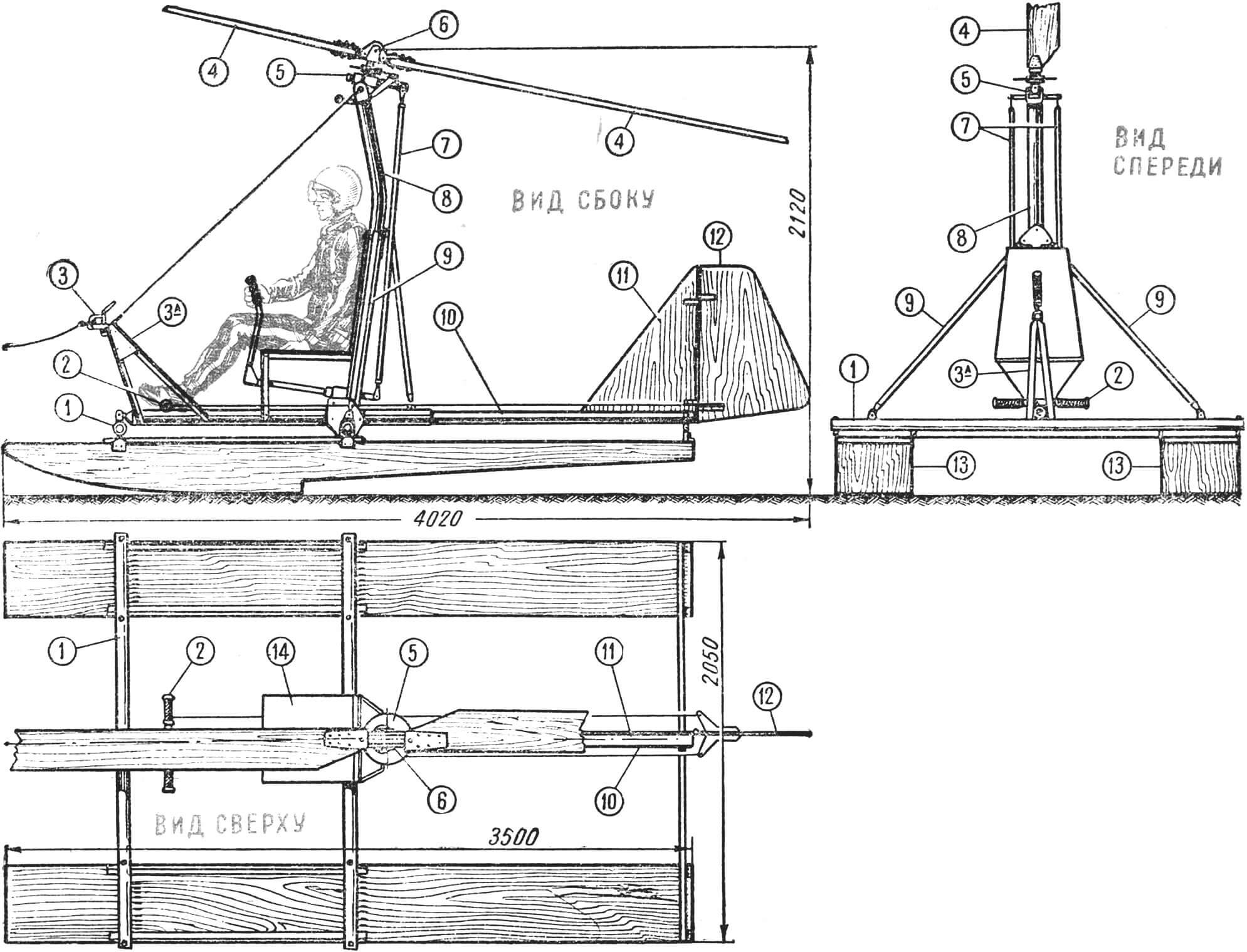
1 – horizontal frame of the load-bearing frame, 2 – steering wheel control pedals, 3 – towing lock, 3a – pylon for attaching the towing lock and instrument panel, 4 – rotor blade, 5 – rotor rotary head, 6 – rotor bushing, 7 – vertical control rod rotor, 8 — rotor strut, 9 — rotor strut struts, 10 — backbone tube of the load-bearing frame, 11 — keel, 12 — rudder, 13 — floats, 14 — pilot’s seat.
CONSTRUCTION : the load-bearing frame (Fig. 1) is formed by four steel pipes St. 45. Three pipes are located horizontally and carry attachment points for floats, tail, towing device and pilot’s seat. The rotor bushing 6, the seat back 15a and control parts are attached to the vertical pipe 8. The frame pipes are connected to each other by gussets made of steel St. 45 bolt on. The vertical post is supported by tubular struts 13 and is relieved from the action of the bending moment by a cable 17 connecting the upper unit with the towing lock pylon. Floats 9 have a wooden frame with plywood sheathing and are covered with fiberglass cloth and epoxy resin. Fastening the floats to the load-bearing frame using steel units Art. 45.
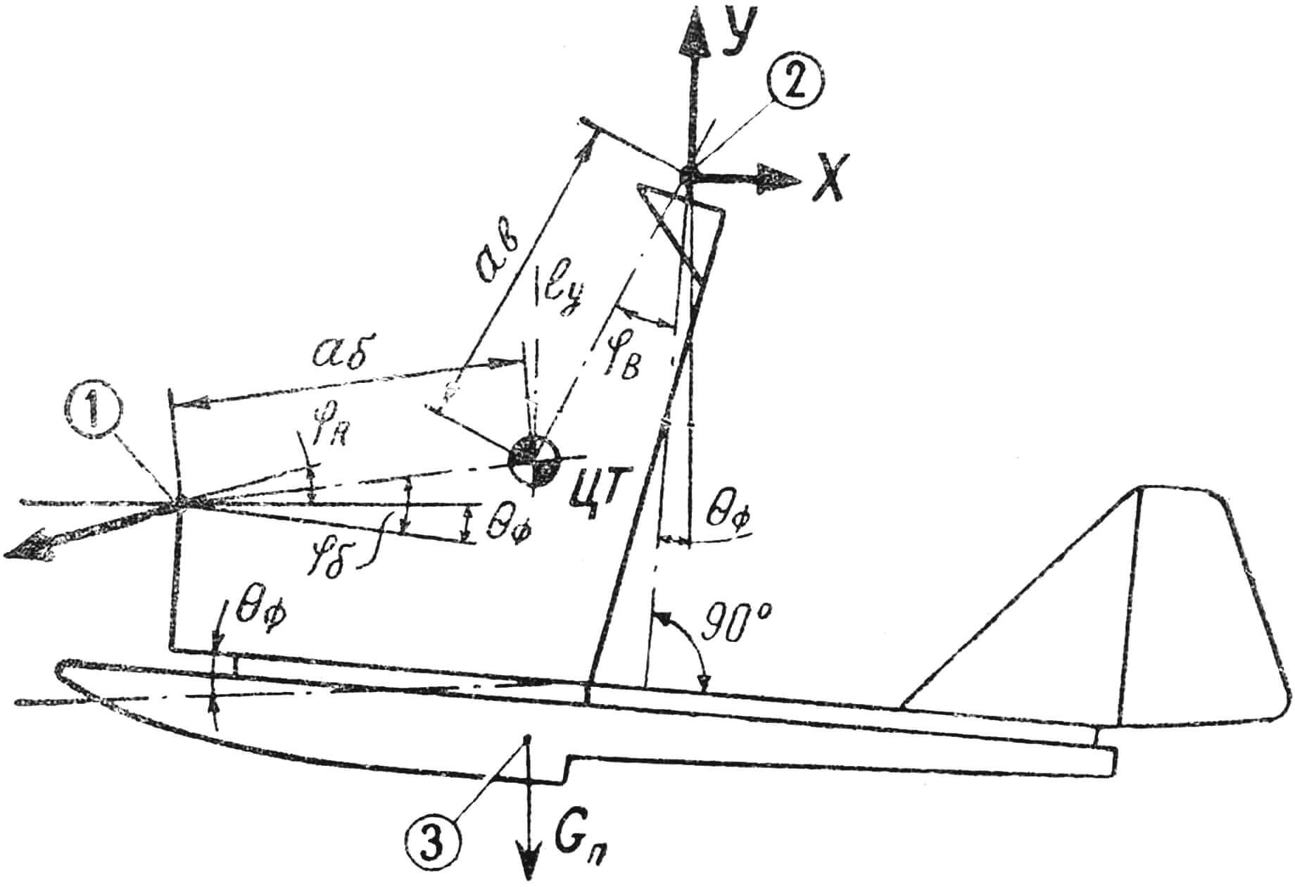
CG – center of gravity of the system, 1 – attachment point of the towing rope, 2 – rotor axis, 3 – center of gravity of the floats, Yв – centering angle, θф – pitch angle of the fuselage, Rт – towing rope thrust, Gп – float weight, Yк – tilt angle cable to the horizon, Yb is the angle of inclination of the line Ab to the construction axis.
ROTOR 2-blade, on a wooden spar glued together from thin plates, filled with foam, covered with fiberglass cloth and epoxy resin. Fill factor = 0.0382. Blade installation angle = +3°, rotor taper angle -4°, rotor speed – 400.
TERRAIN : keel and rudder for turns 6 and 7 – made of sheet plywood 3 mm thick.
Longitudinal and transverse CONTROL is carried out by tilting the rotor hub, connected by a system of rods and levers to an aircraft-type control handle 13. Directional control is carried out by the steering wheel 12, connected by cable wiring to the foot pedals.
Recommend to read
 MAGNETIC MOUSETRAP
According to this principle, before doing traps for birds: foldable cover charge was based on a vertical stick-backup, which in turn was mounted on "cautious" horizontal. Cost the bird...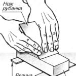 HOLD THE STRIPS
Knife planer should have a perfect sharpness, so then it has to be sharpened. It is usually the abrasive on a flat block, which strives to glide along the table, from which straying to...
