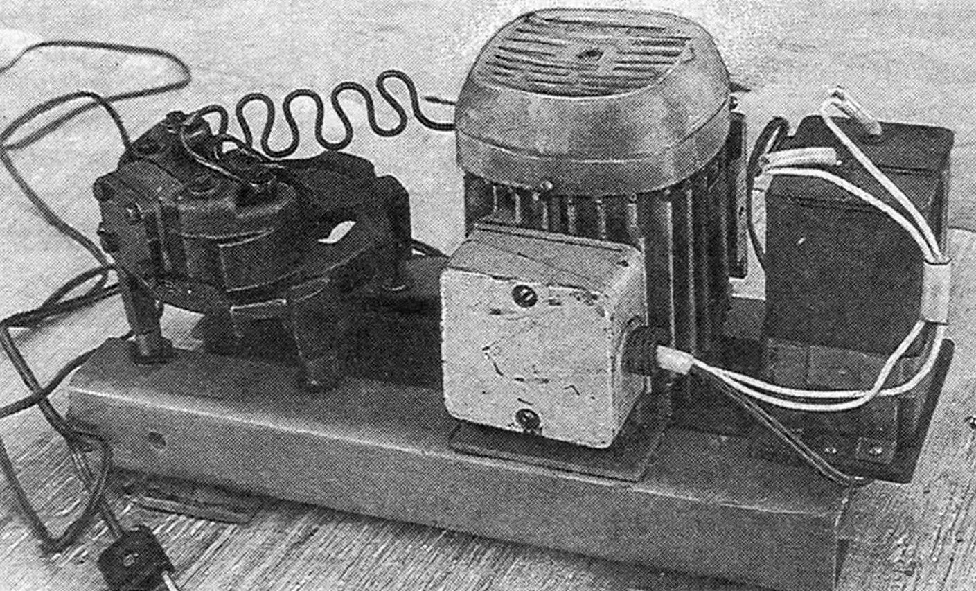
The advantage of a paint sprayer is well known: it provides quality coverage. Moreover, achieving smooth transitions from one color or tone to another can only be done by spraying. And for this, you need to have a compressor in your home workshop. It won’t sit idle after apartment renovations either, and will come in handy for inflating bicycle and car tires, spraying fertilizers in the garden. And it doesn’t have to be store-bought.
I once read in “Modelist-Konstruktor” that you can make a compressor from a refrigerator unit that has served its time. It mentioned a design with a working electric motor. I got a burned-out one. So I had to make do with only the piston mechanism. To extract it, I sawed the unit’s housing in two places with a hacksaw. After unscrewing four mounting bolts, I removed the stator from one side and the pump with rotor from the other. Since the rotor was no longer needed, I knocked it off the crankshaft.
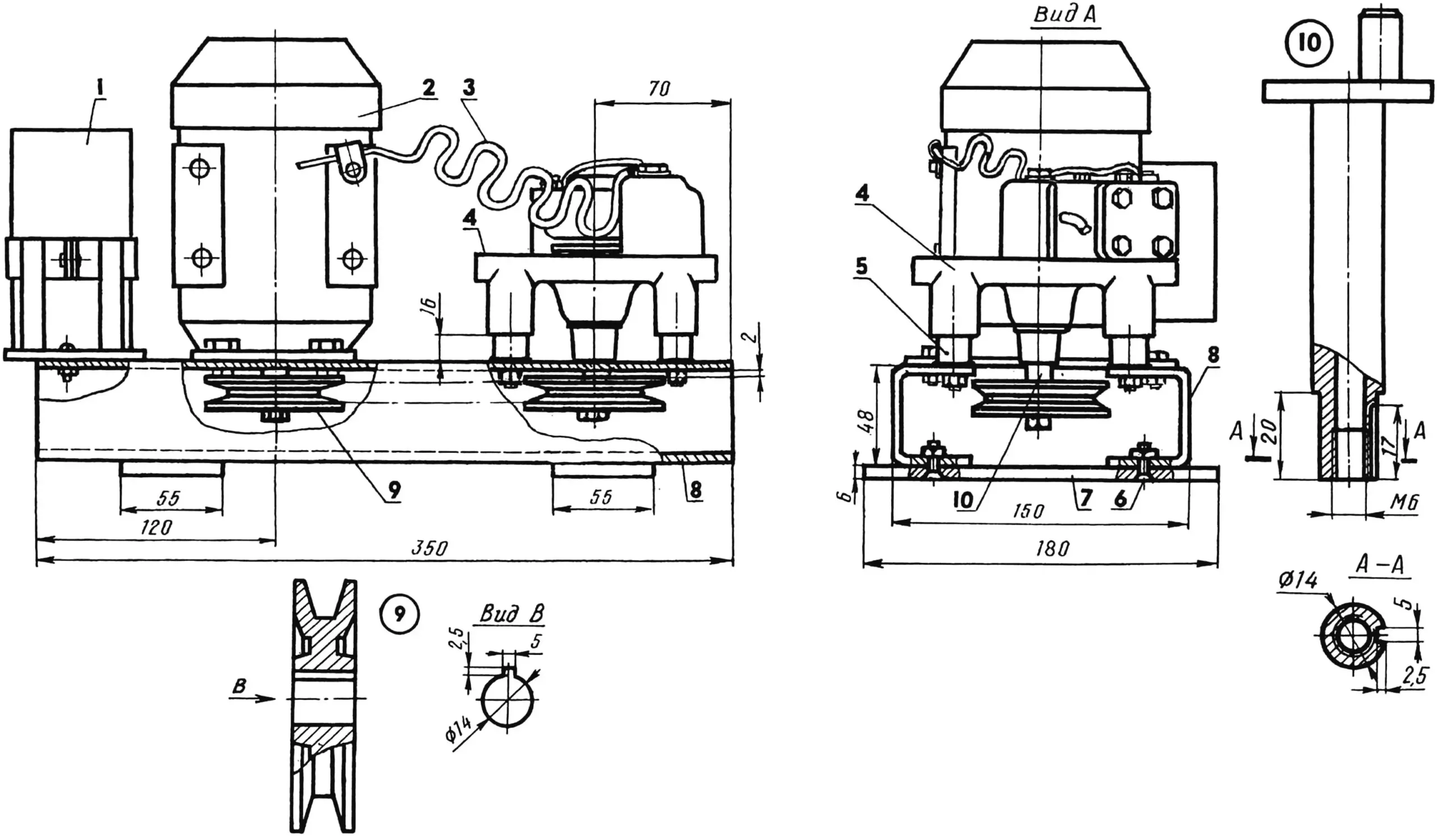
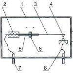
1 — condenser, 2 — electric motor, 3 — air outlet tube, 4 — pump, 5 — bushing (4 pcs.), 6 — mounting screw (8 pcs.), 7 — cross member (2 pcs.), 8 — frame channel (2 pcs.), 9 — pulley (2 pcs.), 10 — crankshaft.
I quickly found a replacement for the burned-out electric motor—from a washing machine, three-phase, model 4 AA 50 V4UZ with a power of 90 W at 1320 rpm. The drive to the pump in my design is belt-driven. For this, I put pulleys with prismatic keys from the washing machine on the motor shaft and pump crankshaft ends and secured them with M6 bolts. I milled the keyway on each shaft beforehand. But you can also drill it. For this, you’ll need an auxiliary bushing with a 14 mm diameter hole. You need to put it on the shaft end and drill a 5 mm diameter hole exactly at the joint, then remove the bushing. In cross-section, the keyway turns out semicircular, so the key itself should be given the same shape.
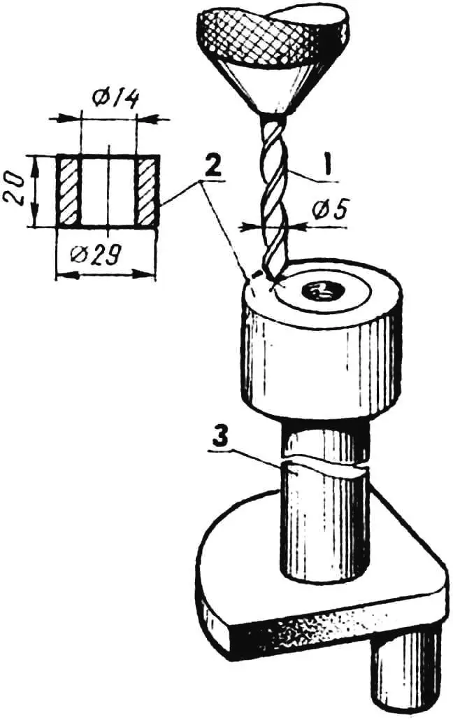
1 — drill, 2 — auxiliary bushing, 3 — pump crankshaft.
My compressor’s frame is made from two channels connected by cross members—steel plates on screws. The pump is attached to the frame with four bolts with bushings mounted on them, the height of which was adjusted on-site. The motor is mounted on a base plate. By moving along the frame’s adjustment holes, it allows for tensioning the V-belt.
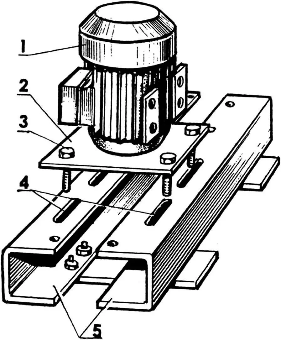
1 — electric motor, 2 — base plate, 3 — mounting bolt (4 pcs.), 4 — frame adjustment holes, 5 — frame channels.
During operation, it turned out that with a sufficiently long air duct tube, using a receiver is not necessary. But on the other hand, it can also work as an oil separator.
“Modelist-Konstruktor” No. 1’97, V. VESELOV
Recommend to read
 YOUR E-PSYCHOLOGIST
A set of electronic devices that use psychologists is constantly expanding. In addition to the "Polygraph" (the"lie detector"), there are other devices to test the emotional state of... SHOWER CURTAIN-“AUTOMATIC”
The popular hosts of all sorts of blinds and curtains on the Windows and interior doors, consisting of two sliding panels for a more decorative are hung on wooden rods with big rings. If...
