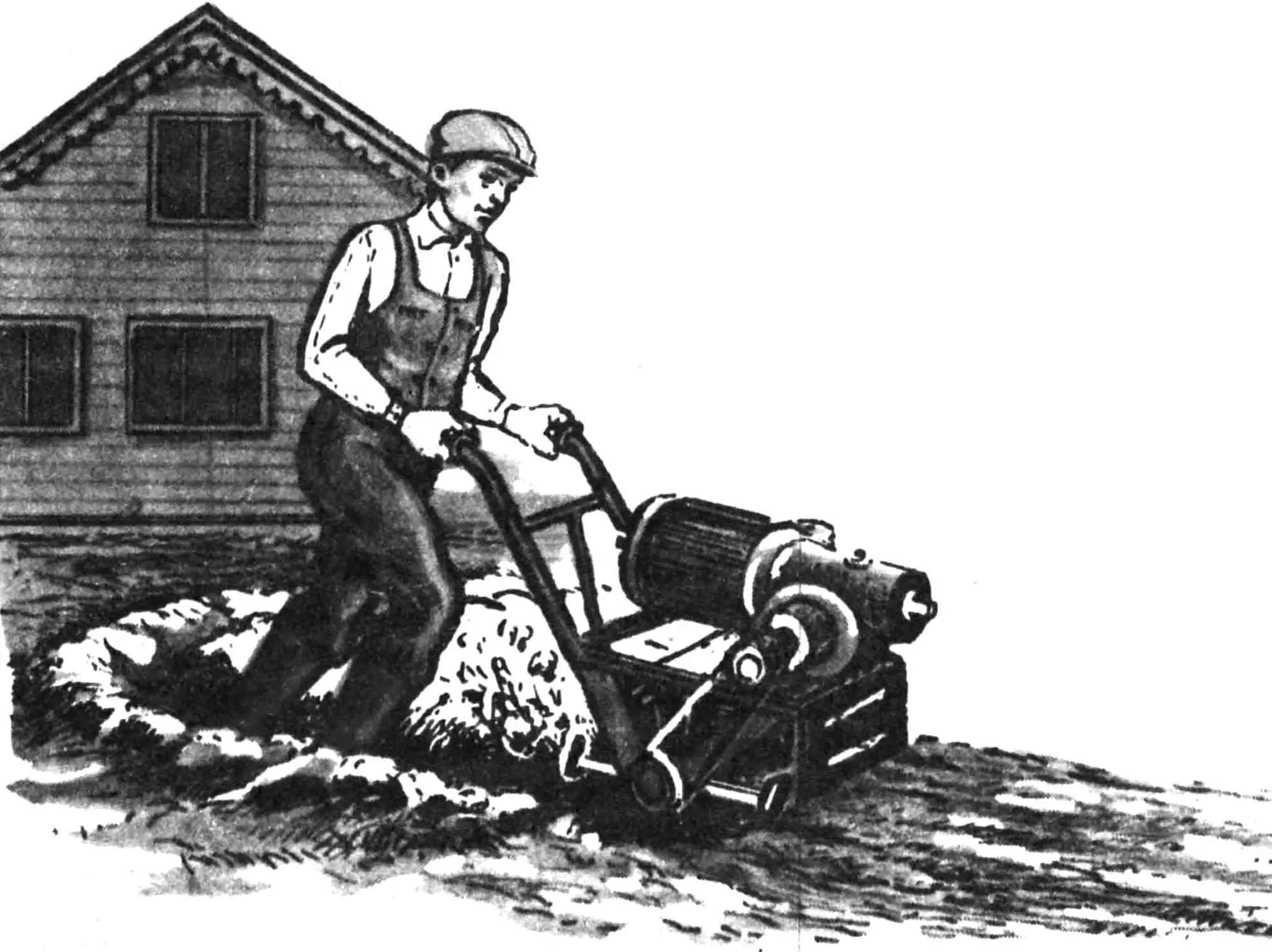
The electric tiller is designed for processing soil in garden and vegetable plots, and for hilling potatoes. Given the particularly harsh operating conditions—long continuous operation (up to 4 hours), constant overload, dirt—preference was given to a heavier and oversized three-phase motor of industrial, enclosed design, over a commutator, direct current motor.
The three-phase asynchronous motor operates in a single-phase connection circuit with a capacitor (star connection). The required capacitance of the capacitor bank
Ср = 2800 Iном/Uном,
where Uном is the (rated) voltage of the electric motor, Іном is the (rated) current.
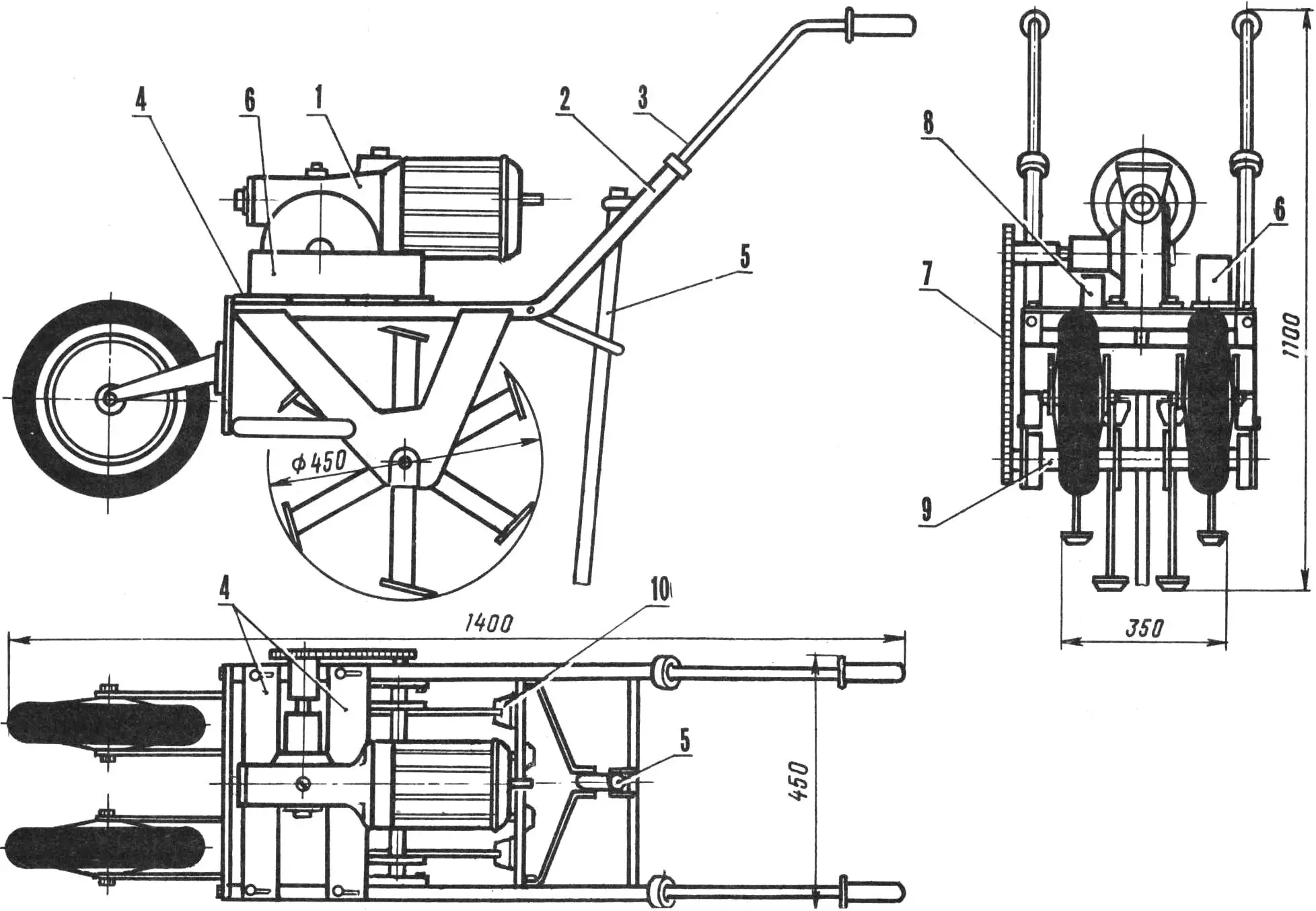
1 — motor-reducer, 2 — frame, 3 — control handles, 4 — motor-reducer mounting plates, 5 — brake, 6 — main capacitor bank, 7 — chain, 8 — starting capacitors, 9 — tiller shaft, 10 — tiller blade.
The basis of the design is a motor-reducer from the RM rail-cutting machine, which has the following characteristics:
Motor — asynchronous, squirrel-cage;
Power — 1 kW;
Voltage — 220 V;
Current — 4.2 A (three-phase);
Motor speed — 1410 rpm;
Efficiency — 0.79;
Output shaft speed — 44 rpm;
Gear ratio — 32;
Weight of motor-reducer — 24.5 kg.
The tiller layout is based on the condition of equilibrium in the working position to reduce forces on the control handles. The motor-reducer drives the tiller shaft into rotation via a chain drive (pitch — 18.25 mm, number of links 52). The drive can be used with i = 1 or i = 1.17, z1 = 13(15); z2 = 15. In this case, the tiller shaft speed is 44 or 38 rpm.
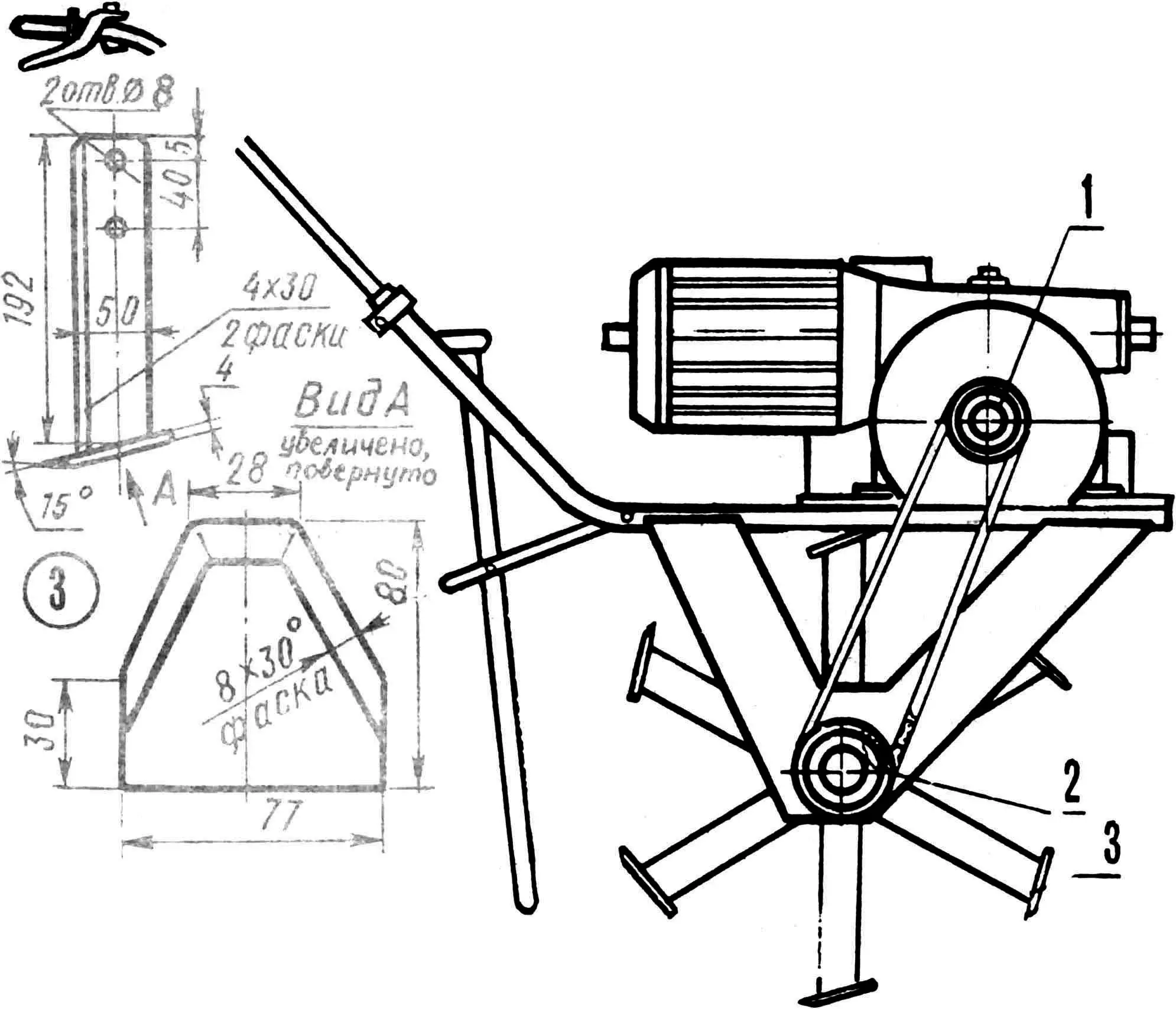
1 — drive sprocket Z1 = 15 or Z1 = 13, 2 — driven sprocket Z2 = 15, 3 — blade.
The motor-reducer is mounted on the frame using two transverse duralumin plates 10 mm thick, which are shifted together with the motor-reducer secured to them, adjusting chain tension.
Two side plates made of steel sheet 4—5 mm thick are welded to the frame, which is made from three-quarter-inch diameter pipes, to which the tiller shaft bearings are attached. The bearing units are special, used from a decommissioned agricultural machine, have a housing and collet shaft fixation. Two wheels (size 56X205, model L-155), used for transporting the electric tiller, are installed in the front part of the frame using adjustable brackets. When processing soil, the wheels are removed. The two rear cross members of the frame have brackets for installing a brake adjustable in height and tilt. The control handles are adjustable both in height and angle.
The electric tiller is powered by single-phase alternating current at 220V (with the three-phase asynchronous motor connected to a single-phase network with capacitor capacitances) or three-phase current at 220 V. Connection of the electric tiller to a single-phase network is carried out using household extension cords. It should also be noted that voltage drop leads to a drop in motor torque. Therefore, using wire with a cross-sectional area of less than 0.8 mm2 is not allowed. During operation, the condition of contacts and connectors should be carefully monitored, checking whether they are overheating.
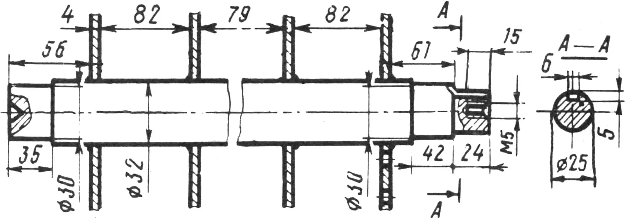
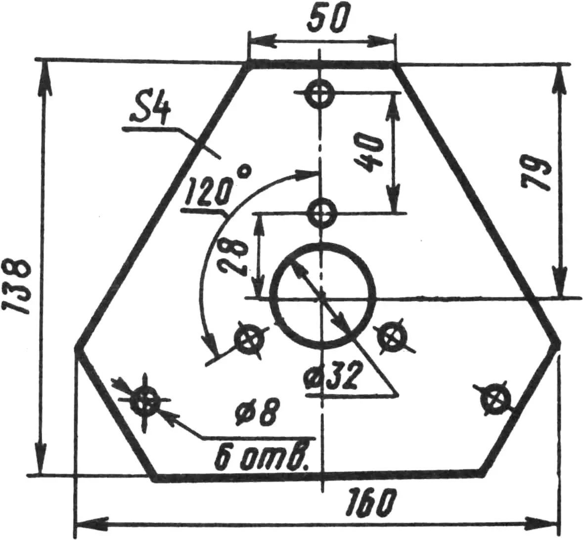
Starting and stopping the motor is carried out by button КУ-2 or 011 УЗ using a lever installed on the right control handle. On the left handle—a similar button for connecting the starting capacitance. Safety is ensured by turning off the motor when releasing the right handle lever, as well as using rubber-sheathed cable, both for power supply and for all intermediate connections. The tiller is a shaft Ø 32 mm with four hexagonal plates made of 5 mm steel sheet installed on it. Three blades are attached to each plate using bolts (see fig.). They have a significant “support” surface, and the installation angle determines the amount of soil layer processed by the next blade (with insufficient “support” surface, the soil layer capture by each blade increases significantly, leading to motor stoppage). Sickle-shaped blades with a “support” surface width of 25 mm were tested (see “Modelist-Konstruktor” No. 7, No. 10, 1987). With such blades, the machine weight turned out to be excessive, the tiller sharply plunged into the ground and stopped.
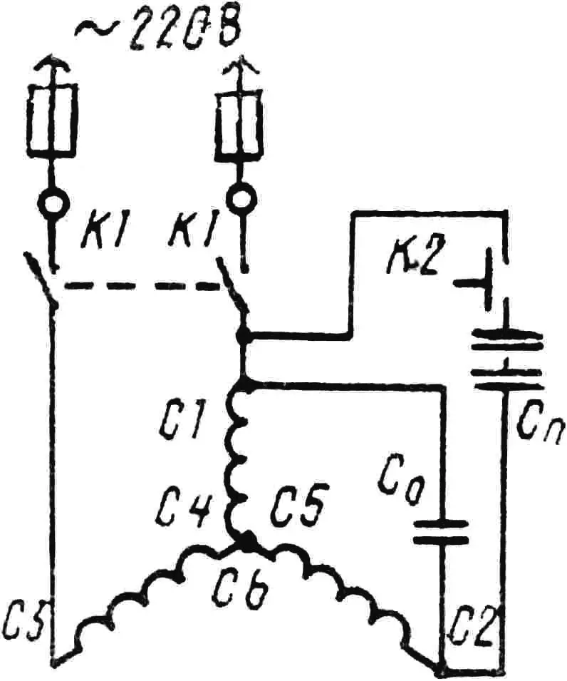
Essential in the tiller operation is the installation and adjustment of the brake. On the electric tiller, it is located at a distance of 380 mm from the center of the tiller shaft and 160 mm below the shaft center (with the machine in horizontal position). During tiller operation, part of the weight almost constantly falls on the brake. Motor torque is not always sufficient at full tiller load, so forward movement is achieved by briefly unloading the brake through light vertical rocking of the handles. A box with capacitors of 65 µF capacity is located on the left side of the motor-reducer. Electrolytic capacitors with a total capacity of 60 µF are used as starting capacitors. In this case, the maximum voltage on the capacitor banks (in idle mode) will be Uxx = 1.15U; Uxx = 253 V.
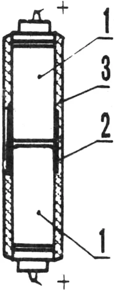
1 — capacitor, 2 — metal connecting clamp, 3 — insulation coating.
A possible area of application for the unit may also be milling dense snow and ice from sidewalks. It can also serve as a unit for pumping liquid. In this case, the drive chain is removed, and a water pump (for example, from diesel K-661M) is installed on the rear side of the engine.
ELECTRIC TILLER TECHNICAL SPECIFICATIONS
Length — 1400 mm
Width — 450 mm
Height — 1100 mm
Tiller diameter — 450 mm
Tiller speed — 44 or 38 rpm
Width of processed soil layer — 350 mm
Depth of processed soil layer — 150—250 mm
Weight — 46 kg
Motor power — 1 kW (when using 3-phase current 220 V),
— 700—750 W (when using single-phase current 220 V).
P. KOPYEV
Recommend to read
 RECORD HOLDER… SIMPLICITY
If in the famous Guinness book of records recorded the simplicity and manufacturability, today we present to your attention a model would be the first contender for such a record....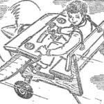 DESK OF SPEED SPECIALIST
"Wow, beautiful..." — that was the unanimous opinion of the participants about our high-speed cord models. After a short discussion, the boys made a "sentence" is a set of custom-making...
